Power Cable Fault Location - Medium & High Voltage Cables

DC testing has been accepted for many years as the standard field method for performing high-voltage tests on cable insulation systems. Whenever DC testing is performed, full consideration should be given to the fact that steady-state direct voltage creates within the insulation systems an electrical field determined by the geometry and conductance of the insulation, whereas under service conditions, alternating voltage creates an electric field determined chiefly by the geometry and dielectric constant (or capacitance) of the insulation. Under ideal, homogeneously uniform insulation conditions, the mathematical formulas governing the steady-state stress distribution within the cable insulation are of the same form for DC and for AC, resulting incomparable relative values; however, should the cable insulation contain defects in which either the conductivity or the dielectric constant assume values significantly different from those in the bulk of the insulation,the electric stress distribution obtained with direct voltage will no longer correspond to that obtained with alternating voltage.

More Related Content
What's hot
What's hot (20)
Viewers also liked
Viewers also liked (18)
Similar to Power Cable Fault Location - Medium & High Voltage Cables
Similar to Power Cable Fault Location - Medium & High Voltage Cables (20)
More from Thorne & Derrick International
More from Thorne & Derrick International (20)
Recently uploaded
Recently uploaded (20)
Power Cable Fault Location - Medium & High Voltage Cables
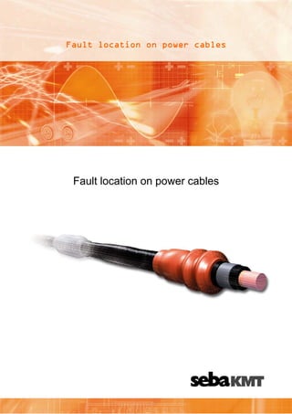
- 1. Fault location on power cables Fault location on power cables
- 2. Contents: 1. 2. 3. 1. Introduction Construction of power cables Cable faults Introduction Fault location on communication and power cables is a very specialized area of electrical technology. The performance of efficient fault location is very much dependant on good logistics and knowledge. Fast and reliable fault location is dependent on these factors if prelocation of a fault is to be done with high accuracy. The following pinpointing procedure, for the exact location of the fault location, can be done on a very short segment of the cable. Cable testing, cable diagnosis and partial discharge measurements, will become of higher importance in the future. The condition based preventive maintenance of cable networks, will more and more replace the event oriented maintenance of cable installations. A good detailed knowledge of the construction of cable networks, cable types and their accessories, simplifies the evaluation of the measured results considerably. Many of these are processes are the essential grounds for correct decisions to be made. The types of cable faults and the required steps to do a cable fault location or a diagnosis are one of the most important details that the technician must be aware of. 2. Construction of power cables The purpose of power cables is for the efficient distribution of electrical energy, Distrubution must be done with a high degree of reliability and safety over a very long period of time. Depending on the application, external environmental and local factors, for example, ground water level, type of ground or voltage levels, different types of cables are used. Cables with impregnated insulation,such as PILC, were installed until the late 60’s and are still being installed in some areas. These cables are today mostly replaced by cables with PVC, EPR, PR or XLPE insulation. Resulting from the changing characteristics of cables their faults and testing have changed considerably. The following chapters cannot cover all of the possible different constructions and varieties of cables and their different materials, but it will concentrate on the most important details only. Many of the following details are not for the explanation of these said details, but more so to help understand and follow the used wording in our fault location guide. 2
- 3. Basic Cable construction Fig. Single core 1.1. Multi core shielded Multi core unshielded Conductor The purpose of the conductor is for current transmission and consists of soft electrolytic copper or pure aluminium. It can be round, sector shaped, single wire or multi stranded construction. 1.2. Insulation The purpose of the insulation is for voltage resistivity and potential separation of conductors from each other and from the metallic outer jacket (Lead Sheath, Armour). 1 to 10 kV: 1 to 30 kV: Mass impregnated paper (PILC) Polyvinylchloride (PVC) Mass impregnated paper (PILC) Cross linked Polyethylene (XLPE) Ethylene Propylene Rubber (EPR) From 60 kV Paper with Oil or Gas Cross linked Polyethylene (XLPE) Besides these typical materials, there are also different types of insulation in existance. 1.3. Semi conducting layers (at nominal voltages from 6 kV The purpose of semi-conducting layers is for the prevention of partial discharges (PD) and high electrical fields inside the cable. Semiconducting layers soften the electrical field which builds up around each single conductor strand and avoids discharge which may occur due to increased electrical fields which may cause damage to the cable Other types of semi conducting layers are today being used for the outer insulating sheath / jacket. The purpose here is for example, to locate sheath faults on cables that are installed in ducts, where the return for the fault current through earth is non existent. 3
- 4. 1.4. Metallic sheath The purpose of the metallic sheath is for protection and sealing from humidity, conduction of leakage or earth fault currents, potential equalisation, earth conductor and neutral concentric. For very important cables and for sub sea cables it can also provide strong mechanical protection. 1.5. Sheath / Jacket Shield (at MV- and HV cables) The purpose of the shield is for conduction of leakage, earth fault current and field control. 1.6. Armour Semiconductor Insulation / Dielectric The purpose of the armour is for Mechanica protection, It can consists of steel bands, flat wires, round wires etc. In some cases this armouring can consist of several different layers. 1.7. Shield / Screen Inner Semiconductor Core / Conductor Plastic sheath The purpose of the plastic sheath is for outer protection of the cable and it consists of PVC or PE. 4
- 5. Cable faults Depending on the type of cable fault, a suitable procedure must be selected. In the cable fault location the general differentiation is divided into the following fault types. 1.8. Fault Conductor - conductor (parallel Fault) Connection between two or more conductors. The insulation resistance value of the fault can be between 0 Ohms (low resistivity) or several M Ohms (high resistivity). L1 2 L3 Shield 1.9. Fault Conductor - shield (parallel Fault) Connection between Conductor and shield or Conductor/Conductor and shield. The insulation resistance value of the fault can be between 0 Ohms (low resistivity) or several M Ohms (high resistivity). Experience has shown, that most faults are in this category. L1 L2 L3 Shield 1.10. Flashing fault (parallel Fault) Very high resistance fault. The cable can be charged. The flashover happens typically at some kV and is very often located in Joints. The cable acts comparable to an arc gap, where the distance between the electrodes determines the voltage. The insulation resistance of this fault is typically infinite up to the breakdown voltage. L1 L2 L3 Shield 5
- 6. 1.11. Serial fault (Open, Interrupt) Faults of this type can be very high resistive up to infinite (complete cut). Very often these type of faults are a combination of serial and parallel insulation resistances. The reason for this being a complete cut of the cable, or it is pulled out of the joint, which interrupts everything, but also permits flashovers in all possible variations. If the conductor is partially burned off (Aluminium) we speak of longitudinal faults. L1 L2 L3 Shield 1.12. Earth faults, sheath faults Faults between the metallic shield and surrounding soil in case of plastic insulated cables. Faults between the Conductor and surrounding soil on LV and plastic insulated cables. Especially for these type of faults the highest precaution must be taken when using high voltage, this is of utmost importance, since the voltage discharges directly to earth. Resulting an increased potential danger to man and animal. L1 L2 L3 Shield 6
- 7. 1.13. Humid / wet faults On multi core cables, often all conductors are affected. The flashover does not always appear at the position where the water entered the cable. The fault resistance is in the range of several k Ohms. At the fault location, impedance changes do occur. Depending on the cable construction (e.g. longitudinal water sealing) these faults can be punctual or widespread throughout the cable. Humidity faults are the most difficult faults to locate. They have the tendency to change during the fault location procedure, partially in a very drastic manner, which occurs especially in Joints, the fault can become high resistive again after one or two discharges and then cannot be localised anymore. The water gets blown out of the joint and dries up. Other forms of humidity faults are underwater faults. Here the water pressure prevents an effective ignition of the fault during the HV application. The location of these faults can be very difficult to.pinpoint. L1 L2 L3 Shield Comments For fault resistance values there is a global differentiation between short circuit, resistive and high resistive faults. The details of this said information has a significant influence on the further procedures to be used during the fault location. These details are described in one of the following articles. CABLE JOINTS, CABLE TERMINATIONS, CABLE GLANDS, CABLE CLEATS FEEDER PILLARS, FUSE LINKS, ARC FLASH, CABLE ROLLERS, CUT-OUTS 11KV 33KV CABLE JOINTS & CABLE TERMINATIONS FURSE EARTHING www.cablejoints.co.uk Thorne and Derrick UK Tel 0044 191 490 1547 Fax 0044 191 477 5371 Tel 0044 117 977 4647 Fax 0044 117 9775582 7