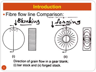
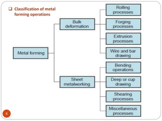
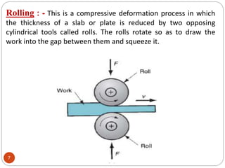
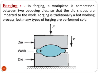
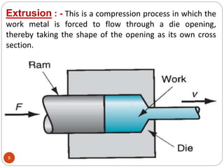
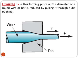
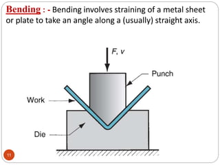
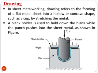
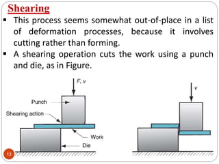
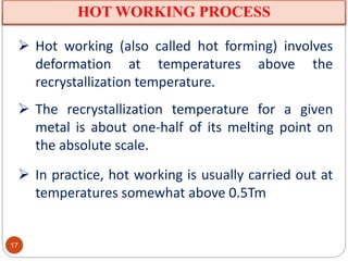
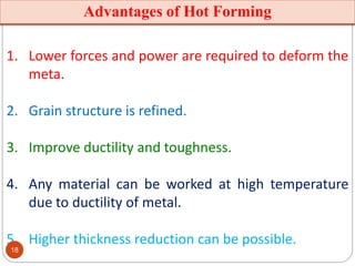
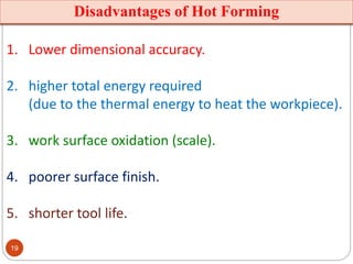
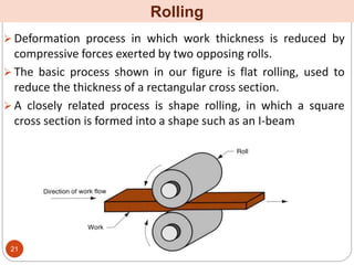
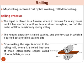
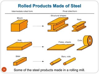
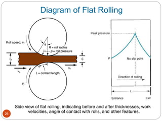
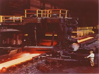
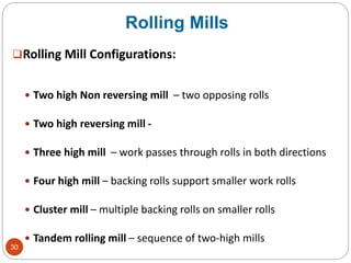
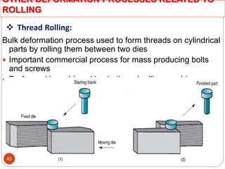
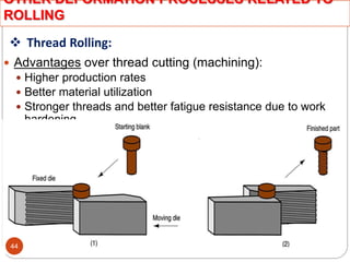
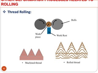
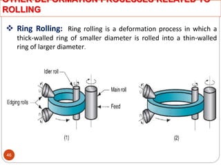
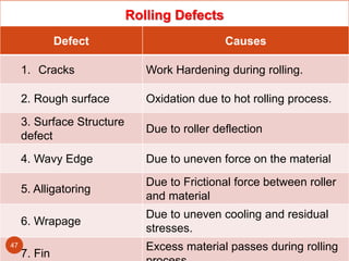
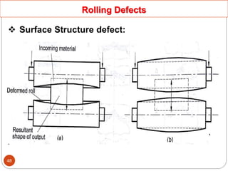
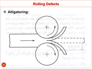
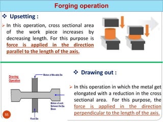
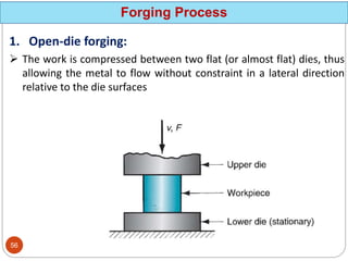
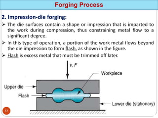
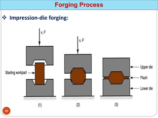
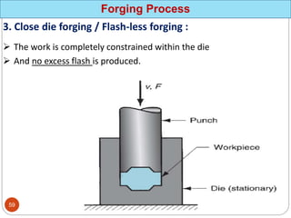
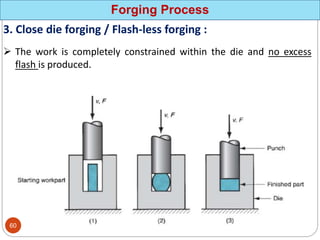
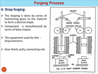
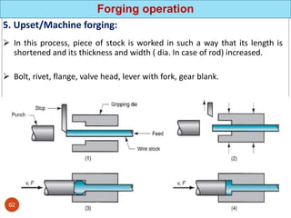
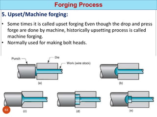
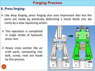
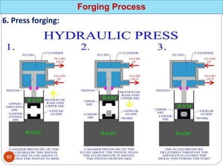
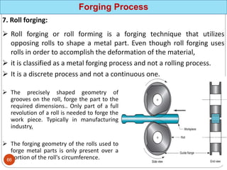
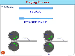
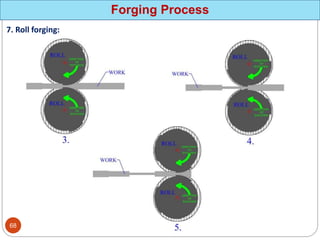
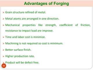
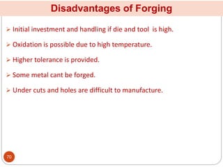
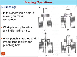
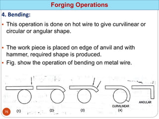
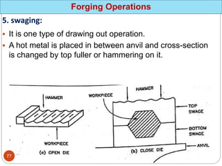
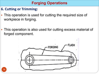
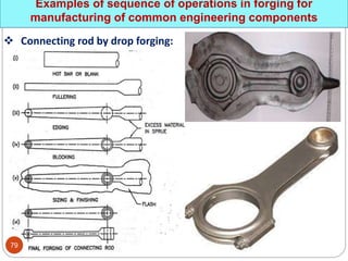
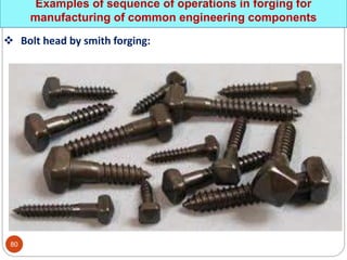
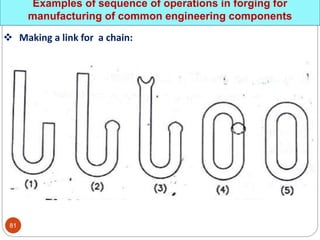
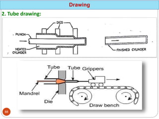
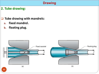
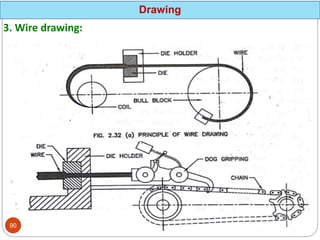
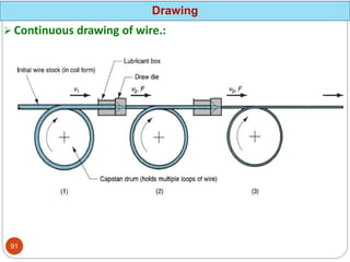
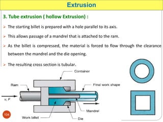
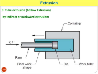
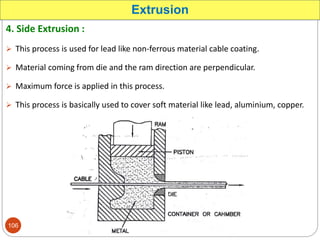
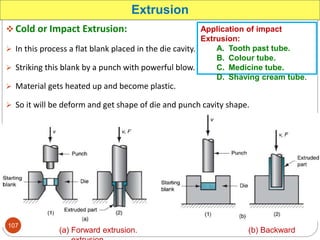
Prepared By:-
Mr. A M Ambaliya
Dr. S. & S. S. Ghandhy College of
Engineering & Technology, Surat.
Manufacturing Engineering-I (4331903)
3rd Semester Diploma Mechanical Engineering
1
Introduction
 Metal forming includes a large group of
manufacturing processes in which
plastic deformation is used to change
the shape of metal workpieces.
 Deformation results from the use of a
tool, usually called a die in metal
forming, which applies stresses that
exceed the yield strength of the metal.
The metal therefore deforms to take a
2
Introduction
 Stresses applied to plastically deform
the metal are usually compressive.
 However, some forming processes
stretch the metal, while others bend the
metal, and still others apply shear
stresses to the metal. To be successfully
formed, a metal must possess certain
properties.
3
Introduction
 Desirable properties include low yield
strength and high ductility. These
properties are affected by temperature.
Ductility is increased and yield strength
is reduced when work temperature is
raised.
4
Introduction
 Fibre flow line Comparison:
5
 Classification of metal
forming operations
6
Rolling : - This is a compressive deformation process in which
the thickness of a slab or plate is reduced by two opposing
cylindrical tools called rolls. The rolls rotate so as to draw the
work into the gap between them and squeeze it.
7
Forging : - In forging, a workpiece is compressed
between two opposing dies, so that the die shapes are
imparted to the work. Forging is traditionally a hot working
process, but many types of forging are performed cold.
8
Extrusion : - This is a compression process in which the
work metal is forced to flow through a die opening,
thereby taking the shape of the opening as its own cross
section.
9
Drawing : - In this forming process, the diameter of a
round wire or bar is reduced by pulling it through a die
opening.
10
Bending : - Bending involves straining of a metal sheet
or plate to take an angle along a (usually) straight axis.
11
Drawing
 In sheet metalworking, drawing refers to the forming
of a flat metal sheet into a hollow or concave shape,
such as a cup, by stretching the metal.
 A blank holder is used to hold down the blank while
the punch pushes into the sheet metal, as shown in
Figure.
12
Shearing
 This process seems somewhat out-of-place in a list
of deformation processes, because it involves
cutting rather than forming.
 A shearing operation cuts the work using a punch
and die, as in Figure.
13
COLD WORKING PROCESS
 Cold working (also known as cold forming) is
metal forming performed at room temperature
or slightly above or below Recrystallisation
Temperature.
14
Advantages of Cold Forming
1. Greater accuracy, meaning closer tolerances can be
achieved.
2. Better surface finish.
3. Improve strength and hardness of the part due to
strain hardening.
4. Grain flow during deformation provides the
opportunity for desirable directional properties to be
obtained in the resulting product.
5. No heating of the work is required, which saves on
furnace and fuel costs and permits higher production
rates
15
Disadvantages of Cold Forming
1. Higher forces and power are required to perform
the operation.
2. Care must be taken to ensure that the surfaces of
the starting workpiece are free of scale and dirt.
3. Ductility and strain hardening of the work metal
limit the amount of forming that can be done to
the part.
16
HOT WORKING PROCESS
 Hot working (also called hot forming) involves
deformation at temperatures above the
recrystallization temperature.
 The recrystallization temperature for a given
metal is about one-half of its melting point on
the absolute scale.
 In practice, hot working is usually carried out at
temperatures somewhat above 0.5Tm
17
Advantages of Hot Forming
1. Lower forces and power are required to deform the
meta.
2. Grain structure is refined.
3. Improve ductility and toughness.
4. Any material can be worked at high temperature
due to ductility of metal.
5. Higher thickness reduction can be possible.
18
Disadvantages of Hot Forming
1. Lower dimensional accuracy.
2. higher total energy required
(due to the thermal energy to heat the workpiece).
3. work surface oxidation (scale).
4. poorer surface finish.
5. shorter tool life.
19
Rolling
Process
20
 Deformation process in which work thickness is reduced by
compressive forces exerted by two opposing rolls.
 The basic process shown in our figure is flat rolling, used to
reduce the thickness of a rectangular cross section.
 A closely related process is shape rolling, in which a square
cross section is formed into a shape such as an I-beam
Rolling
21
 Most rolling is carried out by hot working, called hot rolling.
Rolling
 The ingot is placed in a furnace where it remains for many hours
until it has reached a uniform temperature throughout, so that the
metal will flow consistently during rolling
 The heating operation is called soaking, and the furnaces in which it
is carried out are called soaking pits
Rolling Process:-
 From soaking, the ingot is moved to the
rolling mill, where it is rolled into one
of three intermediate shapes called
blooms, billets, or slabs
22
 Bloom has a square cross section 150 mm × 150 mm (6 in × 6
in) or larger. (Blooms are rolled into structural shapes and
rails for railroad tracks.)
 Billet is rolled from a bloom and is square with dimensions
40mm × 40mm (1.5 in) on a side or larger. (Billets are rolled
into bars and rods)
 Slab is rolled from an ingot or a bloom and has a rectangular
cross section of width 250mm (10 in) or more and thickness
40 mm (1.5 in) or more. (Slabs are rolled into plates, sheets,
and strips. Hot-rolled plates are used in shipbuilding, bridges,
boilers, welded structures for various heavy machines, tubes
and pipes, and many other products)
 These intermediate shapes are subsequently rolled into final
product shapes.
Rolling
23
Some of the steel products made in a rolling mill.
Rolled Products Made of Steel
24
25
Side view of flat rolling, indicating before and after thicknesses, work
velocities, angle of contact with rolls, and other features.
Diagram of Flat Rolling
26
 Basic Elements of Rolling Mills:
A. Rolls.
B. Bearing And its Housing.
C. Drive.
Rolling
27
Types of Rolling
Based on workpiece geometry :
Flat rolling – used to reduce thickness of a rectangular
cross section
Shape rolling - square cross section is formed into a
shape such as an I-beam, C- section, Angle Section.
Based on work temperature :
Hot Rolling.
Cold rolling.
28
29
Rolling Mills
Rolling Mill Configurations:
 Two high Non reversing mill – two opposing rolls
 Two high reversing mill -
 Three high mill – work passes through rolls in both directions
 Four high mill – backing rolls support smaller work rolls
 Cluster mill – multiple backing rolls on smaller rolls
 Tandem rolling mill – sequence of two-high mills
30
Various configurations of rolling mills: (a) 2-high rolling mill.
Two-High Rolling Mill
31
Various configurations of rolling mills: (b) 3-high rolling mill.
Three-High Rolling Mill
32
Various configurations of rolling mills: (c) four-high rolling mill.
Four-High Rolling Mill
33
 Multiple backing rolls allow even smaller roll diameters
Various configurations of rolling mills: (d) cluster mill
Cluster Mill
34
Planetary Mill
35
 A series Two High rolling stands in sequence
Various configurations of rolling mills: (e) tandem rolling mill.
Tandem Rolling Mill
36
Roll pass
1. Breakdown Passes:
2. Roughing Passes:
3. Finishing Passes:
37
Roll pass
 Breakdown Passes:
1. Box-Pass Series:
2. Diamond-square Series:
3. Oval-square Series:
38
Rolling of Rounds
39
Roll pass sequence for 12mm rod
40
Rolling of Sections
1. Open Pass:
2. Close Pass:
41
Rolling of Sections
1. Beam rolling:
2. Butterfly rolling:
3. Universal rolling:
42
 Thread Rolling:
Bulk deformation process used to form threads on cylindrical
parts by rolling them between two dies
 Important commercial process for mass producing bolts
and screws
 Performed by cold working in thread rolling machines
OTHER DEFORMATION PROCESSES RELATED TO
ROLLING
43
 Thread Rolling:
 Advantages over thread cutting (machining):
 Higher production rates
 Better material utilization
 Stronger threads and better fatigue resistance due to work
hardening
OTHER DEFORMATION PROCESSES RELATED TO
ROLLING
44
Work Rest
Rolls
Work
piece
• Machined thread • Rolled thread
 Thread Rolling:
OTHER DEFORMATION PROCESSES RELATED TO
ROLLING
45
 Ring Rolling: Ring rolling is a deformation process in which a
thick-walled ring of smaller diameter is rolled into a thin-walled
ring of larger diameter.
OTHER DEFORMATION PROCESSES RELATED TO
ROLLING
46
Rolling Defects
Defect Causes
1. Cracks Work Hardening during rolling.
2. Rough surface Oxidation due to hot rolling process.
3. Surface Structure
defect
Due to roller deflection
4. Wavy Edge Due to uneven force on the material
5. Alligatoring
Due to Frictional force between roller
and material
6. Wrapage
Due to uneven cooling and residual
stresses.
7. Fin
Excess material passes during rolling
47
Rolling Defects
 Surface Structure defect:
48
Rolling Defects
 Alligatoring:
49
Forging
Process
50
 Forging is defined as a metal working process by which metal and
alloys are plastically deformed to the desired shapes by application
of compressive force.
 It is the oldest of the metal forming operations, dating back to
perhaps 5000 BCE .
 Today, forging is an important industrial process used to make a
variety of high-strength components for-
 Automobile
 Aerospace.
 These components include- Engine crankshafts and connecting rods,
gears, aircraft structural components, and jet engine turbine parts
Forging
51
Difference between
Forging
And
Rolling
Forging
52
Grain direction / Fiber flow line in forged part
53
 According to Source of energy:
I. Hand forging
II. Machine forging
 According to types of Die:
I. Open die forging.
II. Close die forging.
 According to application of pressure:
I. Drop forging.
II. Press forging.
III. Machine forging.
IV. Impact forging
 According to forging machine:
I. Open die forging.
II. Machine forging.
III. Press forging.
IV. Roll forging
Classification of Forging methods
54
Forging operation
 In this operation, cross sectional area
of the work piece increases by
decreasing length. For this purpose is
force is applied in the direction
parallel to the length of the axis.
 Upsetting :
 In this operation in which the metal get
elongated with a reduction in the cross
sectional area. For this purpose, the
force is applied in the direction
perpendicular to the length of the axis.
 Drawing out :
55
Forging Process
1. Open-die forging:
 The work is compressed between two flat (or almost flat) dies, thus
allowing the metal to flow without constraint in a lateral direction
relative to the die surfaces
56
Forging Process
2. Impression-die forging:
 The die surfaces contain a shape or impression that is imparted to
the work during compression, thus constraining metal flow to a
significant degree.
 In this type of operation, a portion of the work metal flows beyond
the die impression to form flash, as shown in the figure.
 Flash is excess metal that must be trimmed off later.
57
Forging Process
 Impression-die forging:
58
Forging Process
3. Close die forging / Flash-less forging :
 The work is completely constrained within the die
 And no excess flash is produced.
59
Forging Process
3. Close die forging / Flash-less forging :
 The work is completely constrained within the die and no excess
flash is produced.
60
Forging Process
4. Drop forging:
 The shaping is done by series of
hammering given to the material
to form a desired shape.
 Component is manufactured by
series of blow impact.
 The equipment used for this :
Drop hammers
 Gear blank, pully, connecting rod.
61
Forging operation
5. Upset/Machine forging:
 In this process, piece of stock is worked in such a way that its length is
shortened and its thickness and width ( dia. In case of rod) increased.
 Bolt, rivet, flange, valve head, lever with fork, gear blank.
62
Forging Process
5. Upset/Machine forging:
• Some times it is called upset forging Even though the drop and press
forge are done by machine, historically upsetting process is called
machine forging.
• Normally used for making bolt heads.
63
Forging Process
6. Press forging:
 Like drop forging, press forging also uses impression dies but the
parts are made by plastically deforming a metal blank into die
cavity by a slow squeezing action.
 This operation is completed
in single stroke of hydraulic
press ram.
 Heavy cross section like air
craft parts, connecting rod,
bolt, screw, rivet are made
by this process.
64
Forging Process
6. Press forging:
65
Forging Process
7. Roll forging:
 Roll forging or roll forming is a forging technique that utilizes
opposing rolls to shape a metal part. Even though roll forging uses
rolls in order to accomplish the deformation of the material,
 it is classified as a metal forging process and not a rolling process.
 It is a discrete process and not a continuous one.
 The precisely shaped geometry of
grooves on the roll, forge the part to the
required dimensions.. Only part of a full
revolution of a roll is needed to forge the
work piece. Typically in manufacturing
industry,
 The forging geometry of the rolls used to
forge metal parts is only present over a
portion of the roll's circumference.
66
Forging Process
7. Roll forging:
67
Forging Process
7. Roll forging:
68
Advantages of Forging
 Grain structure refined of metal.
 Metal atoms are arranged in one direction.
 Mechanical properties like strength, coefficient of friction,
resistance to impact load are improve.
 Time and labor cost is minimize.
 Machining is not required so cost is minimum.
 Better surface finish.
 Higher production rate.
 Product will be defect free.
69
Disadvantages of Forging
 Initial investment and handling if die and tool is high.
 Oxidation is possible due to high temperature.
 Higher tolerance is provided.
 Some metal cant be forged.
 Under cuts and holes are difficult to manufacture.
70
Application of Forging
 Locomotive and automobile parts like axel, lever, cam, link,
connecting rod, crank shaft.
 Cutting tools, agriculture tools, machine parts, spring, hook, nails,
screw, handle etc.
 Home appliances.
 Scientific product.
 Military products.
 Air craft and missile product.
71
Forging Defects
 Pitting:
 Cold shuts:
 Die shift:
 Dents:
 Burn metal:
 Fins and rags:
 Ruptured fiber structure:
 Cracks:
 Hair cracks:
 Slags and porosity:
 Oxidation and decarburization:
 Incomplete forging product:
72
Forging Operations
1. Upsetting or jumping :
73
Forging Operations
2. Drawing out :
74
Forging Operations
3. Punching:
 In this operation a hole is
making on metal
workpiece.
 Work piece is placed on
anvil, die having hole.
 A hot punch is applied and
impact load is given for
punching hole.
75
Forging Operations
4. Bending:
 This operation is done on hot wire to give curvilinear or
circular or angular shape.
 The work piece is placed on edge of anvil and with
hammer, required shape is produced.
 Fig. show the operation of bending on metal wire.
76
Forging Operations
5. swaging:
 It is one type of drawing out operation.
 A hot metal is placed in between anvil and cross-section
is changed by top fuller or hammering on it.
77
Forging Operations
6. Cutting or Trimming:
 This operation is used for cutting the required size of
workpiece in forging.
 This operation is also used for cutting excess material of
forged component.
78
Examples of sequence of operations in forging for
manufacturing of common engineering components
 Connecting rod by drop forging:
79
Examples of sequence of operations in forging for
manufacturing of common engineering components
 Bolt head by smith forging:
80
Examples of sequence of operations in forging for
manufacturing of common engineering components
 Making a link for a chain:
81
Drawing
Process
82
 Drawing is a cold working process.
 In n which the workpiece (wire, rode and tube) is pulled
through a taper hole in die so as to reduce its Diameter.
 Accurate dimensions, clean and excellent quality of surface is
produce.
 Increase strength and hardness.
 This process is used to manufacture wire, tube, cup, square,
hexagon shape and home appliances.
Drawing
83
Different types of drawing operations:
I. Blank drawing
II. Tube drawing
III. Wire drawing
Drawing
84
1. Blank drawing:
 This process is used to
prepare cup shape from
metal work.
 Under this process a hot
blank is placed on die. Than
pressure is applied by
punch.
 This process is carried out in
different strokes.
 Shallow drawing:
 Deep drawing:
Drawing
𝐷
85
1. Blank drawing:
Drawing
86
Stages in deformation of the work in deep drawing:
Drawing
1. punch makes initial
contact with work.
2. Bending.
3. Straightening.
4. friction and
compression.
5. final cup shape
showing effects of
thinning in the cup
walls.
87
2. Tube drawing:
Drawing
88
2. Tube drawing:
 Tube drawing with mandrels:
a. fixed mandrel.
b. floating plug.
Drawing
89
3. Wire drawing:
Drawing
90
 Continuous drawing of wire.:
Drawing
91
Equipment used in Wire drawing:
1. Hydraulic press:
2. Horizontal draw bench:
3. Continuous wire drawing machine:
4. Drawing die:
5. Drawing punch:
Drawing
92
 Hydraulically operated draw
bench for drawing metal bars:
Drawing
93
Characteristics of drawing process:
1. Strength and hardness is Increased :
2. Accurate dimension and better surface finish:
3. This is cold working process:
4. Blank area can be minimised up to 50%:
5. Chemical and mechanical properties does not change:
Drawing
94
Application of Drawing Process:
 Tubes.
 Cylinders.
 Different shape of vessels.
 Oxygen acetylene gas cylinder.
 Bullets.
 Thin wires.
Drawing
95
Factors affecting the Drawing Process:
A. Workpiece temperature.
B. Pressure.
C. Radius on punch.
D. Radius on die.
E. Friction.
F. Workpiece material.
G. Percentage reduction and depth of draw.
H. Drawing speed.
I. Die clearance.
Drawing
96
Stage of Drawing Process:
A. Place the workpiece blank on die and take the blank holder and
punch in contact.
B. Punch move progressively so workpiece toward die.
C. Metal compress at punch radius and due to that blank
circumference reduce.
D. When punch moves downward at that time the twist part of w.p
become straight at die radius.
(blank holder is required for smooth and wrinkle free product)
Drawing
97
Defects occur in Drawing Process and their causes:
Drawing
Defect Causes
 Wrinkles:
1. If pressure pad and blank holder is not
used.
2. Improper punch.
3. Improper die clearance.
 Excessive
reduction work
piece thickness:
1. Improper punch.
2. Improper die radius.
3. Improper pressure.
 Cracks
1. Improper tool speed.
2. Improper force on blank holder creates
cracks
98
Extrusion
Process
99
 Compression forming process in which work metal is forced to
flow through a die opening to produce a desired
cross-sectional shape.
 Process is similar to squeezing toothpaste out of a toothpaste
tube.
 In general, extrusion is used to produce long parts of uniform
cross sections.
Extrusion
Method of Extrusion Process:
A. Direct / Forward extrusion.
B. Indirect / Backward extrusion.
C. Tube extrusion.
D. Side extrusion.
Two basic types:
 Hot extrusion
 Cold extrusion
100
1. Direct / Forward Extrusion:
 The heated billet is placed in the chamber.
 It is pushed by the ram toward the die.
 The metal is subjected to plastic deformation, slide along the walls
of the chamber and is forced to flow through the die opening.
Extrusion
101
2. Indirect / Backward Extrusion:
 One of the problems in direct extrusion is the significant friction that exists
between the work surface and the walls of the container as the billet is forced to
slide toward the die opening.
 This friction causes increase in the ram force required, which produce very high
residual stress on the container.
Extrusion
Continue
102
2. Indirect / Backward Extrusion:
 In the indirect or backward method the billet does not move relative to the
container.
 So that friction is between the die and chamber.
 The friction force are lower and the power required for extrusion is less than
direct extrusion. (25% to 30% less)
Extrusion
103
3. Tube extrusion ( hollow Extrusion) :
 The starting billet is prepared with a hole parallel to its axis.
 This allows passage of a mandrel that is attached to the ram.
 As the billet is compressed, the material is forced to flow through the clearance
between the mandrel and the die opening.
 The resulting cross section is tubular.
Extrusion
104
3. Tube extrusion (hollow Extrusion)
by indirect or Backward extrusion:
Extrusion
105
4. Side Extrusion :
 This process is used for lead like non-ferrous material cable coating.
 Material coming from die and the ram direction are perpendicular.
 Maximum force is applied in this process.
 This process is basically used to cover soft material like lead, aluminium, copper.
Extrusion
106
 Cold or Impact Extrusion:
 In this process a flat blank placed in the die cavity.
 Striking this blank by a punch with powerful blow.
 Material gets heated up and become plastic.
 So it will be deform and get shape of die and punch cavity shape.
Extrusion
(a) Forward extrusion. (b) Backward
Application of impact
Extrusion:
A. Tooth past tube.
B. Colour tube.
C. Medicine tube.
D. Shaving cream tube.
107
Advantages of Extrusion Process :
 Greater strength and dense structure can be produced.
 Better surface finish and close tolerance is achieved.
 This process is faster and higher production rate.
 Minimum tooling cost.
 Minimum production cost compare to other process.
 Intricate shape can be produced.
108
109
Different Forming operations
A. Curling operation.
B. Bulging operation.
C. Stretch forming operation.
D. Tube forming operation.
110
Forming operations
1. Curling Operation:
 In this process, the end of tube or
sheet part is made round shape.
 Sheet or tube end is placed below
the punch.
 with blow of punch, sheet or tubes
gets the die shape.
 This process is done on ductile
material.
111
Forming operations
2. Bulging Operation:
 This is used to expand the middle
portion of cup shape workpiece.
 In this process two part die is used.
 W.P is placed between die and
rubber.
 Force is applied on top of the rubber
by blow of punch.
112
Forming operations
3. Stretch forming operation:
 This process is used to produced required shape of sheet metal.
 Sheet metal is clamped between two jaws and stretched by punch and jaws.
 This stretch develop tensile stress in sheet metal.
 So Workpiece get permanent deformation and required contour is produced.
113
Forming operations
4. Tube forming operation:
 This process is used to produced required shape of tube.
 Like bending, ball mouth at tube end, reduction and increase in the diameter of
tube can be done.
114
115
Embossing
 In this process, the end of tube or
sheet part is made round shape.
 Sheet or tube end is placed below
the punch.
 with blow of punch, sheet or tubes
gets the die shape.
 This process is done on ductile
material.
116

METAL FORMING PROCESS IN DIPLOMA MECHANICAL

  • 1.
    Prepared By:- Mr. AM Ambaliya Dr. S. & S. S. Ghandhy College of Engineering & Technology, Surat. Manufacturing Engineering-I (4331903) 3rd Semester Diploma Mechanical Engineering 1
  • 2.
    Introduction  Metal formingincludes a large group of manufacturing processes in which plastic deformation is used to change the shape of metal workpieces.  Deformation results from the use of a tool, usually called a die in metal forming, which applies stresses that exceed the yield strength of the metal. The metal therefore deforms to take a 2
  • 3.
    Introduction  Stresses appliedto plastically deform the metal are usually compressive.  However, some forming processes stretch the metal, while others bend the metal, and still others apply shear stresses to the metal. To be successfully formed, a metal must possess certain properties. 3
  • 4.
    Introduction  Desirable propertiesinclude low yield strength and high ductility. These properties are affected by temperature. Ductility is increased and yield strength is reduced when work temperature is raised. 4
  • 5.
    Introduction  Fibre flowline Comparison: 5
  • 6.
     Classification ofmetal forming operations 6
  • 7.
    Rolling : -This is a compressive deformation process in which the thickness of a slab or plate is reduced by two opposing cylindrical tools called rolls. The rolls rotate so as to draw the work into the gap between them and squeeze it. 7
  • 8.
    Forging : -In forging, a workpiece is compressed between two opposing dies, so that the die shapes are imparted to the work. Forging is traditionally a hot working process, but many types of forging are performed cold. 8
  • 9.
    Extrusion : -This is a compression process in which the work metal is forced to flow through a die opening, thereby taking the shape of the opening as its own cross section. 9
  • 10.
    Drawing : -In this forming process, the diameter of a round wire or bar is reduced by pulling it through a die opening. 10
  • 11.
    Bending : -Bending involves straining of a metal sheet or plate to take an angle along a (usually) straight axis. 11
  • 12.
    Drawing  In sheetmetalworking, drawing refers to the forming of a flat metal sheet into a hollow or concave shape, such as a cup, by stretching the metal.  A blank holder is used to hold down the blank while the punch pushes into the sheet metal, as shown in Figure. 12
  • 13.
    Shearing  This processseems somewhat out-of-place in a list of deformation processes, because it involves cutting rather than forming.  A shearing operation cuts the work using a punch and die, as in Figure. 13
  • 14.
    COLD WORKING PROCESS Cold working (also known as cold forming) is metal forming performed at room temperature or slightly above or below Recrystallisation Temperature. 14
  • 15.
    Advantages of ColdForming 1. Greater accuracy, meaning closer tolerances can be achieved. 2. Better surface finish. 3. Improve strength and hardness of the part due to strain hardening. 4. Grain flow during deformation provides the opportunity for desirable directional properties to be obtained in the resulting product. 5. No heating of the work is required, which saves on furnace and fuel costs and permits higher production rates 15
  • 16.
    Disadvantages of ColdForming 1. Higher forces and power are required to perform the operation. 2. Care must be taken to ensure that the surfaces of the starting workpiece are free of scale and dirt. 3. Ductility and strain hardening of the work metal limit the amount of forming that can be done to the part. 16
  • 17.
    HOT WORKING PROCESS Hot working (also called hot forming) involves deformation at temperatures above the recrystallization temperature.  The recrystallization temperature for a given metal is about one-half of its melting point on the absolute scale.  In practice, hot working is usually carried out at temperatures somewhat above 0.5Tm 17
  • 18.
    Advantages of HotForming 1. Lower forces and power are required to deform the meta. 2. Grain structure is refined. 3. Improve ductility and toughness. 4. Any material can be worked at high temperature due to ductility of metal. 5. Higher thickness reduction can be possible. 18
  • 19.
    Disadvantages of HotForming 1. Lower dimensional accuracy. 2. higher total energy required (due to the thermal energy to heat the workpiece). 3. work surface oxidation (scale). 4. poorer surface finish. 5. shorter tool life. 19
  • 20.
  • 21.
     Deformation processin which work thickness is reduced by compressive forces exerted by two opposing rolls.  The basic process shown in our figure is flat rolling, used to reduce the thickness of a rectangular cross section.  A closely related process is shape rolling, in which a square cross section is formed into a shape such as an I-beam Rolling 21
  • 22.
     Most rollingis carried out by hot working, called hot rolling. Rolling  The ingot is placed in a furnace where it remains for many hours until it has reached a uniform temperature throughout, so that the metal will flow consistently during rolling  The heating operation is called soaking, and the furnaces in which it is carried out are called soaking pits Rolling Process:-  From soaking, the ingot is moved to the rolling mill, where it is rolled into one of three intermediate shapes called blooms, billets, or slabs 22
  • 23.
     Bloom hasa square cross section 150 mm × 150 mm (6 in × 6 in) or larger. (Blooms are rolled into structural shapes and rails for railroad tracks.)  Billet is rolled from a bloom and is square with dimensions 40mm × 40mm (1.5 in) on a side or larger. (Billets are rolled into bars and rods)  Slab is rolled from an ingot or a bloom and has a rectangular cross section of width 250mm (10 in) or more and thickness 40 mm (1.5 in) or more. (Slabs are rolled into plates, sheets, and strips. Hot-rolled plates are used in shipbuilding, bridges, boilers, welded structures for various heavy machines, tubes and pipes, and many other products)  These intermediate shapes are subsequently rolled into final product shapes. Rolling 23
  • 24.
    Some of thesteel products made in a rolling mill. Rolled Products Made of Steel 24
  • 25.
  • 26.
    Side view offlat rolling, indicating before and after thicknesses, work velocities, angle of contact with rolls, and other features. Diagram of Flat Rolling 26
  • 27.
     Basic Elementsof Rolling Mills: A. Rolls. B. Bearing And its Housing. C. Drive. Rolling 27
  • 28.
    Types of Rolling Basedon workpiece geometry : Flat rolling – used to reduce thickness of a rectangular cross section Shape rolling - square cross section is formed into a shape such as an I-beam, C- section, Angle Section. Based on work temperature : Hot Rolling. Cold rolling. 28
  • 29.
  • 30.
    Rolling Mills Rolling MillConfigurations:  Two high Non reversing mill – two opposing rolls  Two high reversing mill -  Three high mill – work passes through rolls in both directions  Four high mill – backing rolls support smaller work rolls  Cluster mill – multiple backing rolls on smaller rolls  Tandem rolling mill – sequence of two-high mills 30
  • 31.
    Various configurations ofrolling mills: (a) 2-high rolling mill. Two-High Rolling Mill 31
  • 32.
    Various configurations ofrolling mills: (b) 3-high rolling mill. Three-High Rolling Mill 32
  • 33.
    Various configurations ofrolling mills: (c) four-high rolling mill. Four-High Rolling Mill 33
  • 34.
     Multiple backingrolls allow even smaller roll diameters Various configurations of rolling mills: (d) cluster mill Cluster Mill 34
  • 35.
  • 36.
     A seriesTwo High rolling stands in sequence Various configurations of rolling mills: (e) tandem rolling mill. Tandem Rolling Mill 36
  • 37.
    Roll pass 1. BreakdownPasses: 2. Roughing Passes: 3. Finishing Passes: 37
  • 38.
    Roll pass  BreakdownPasses: 1. Box-Pass Series: 2. Diamond-square Series: 3. Oval-square Series: 38
  • 39.
  • 40.
    Roll pass sequencefor 12mm rod 40
  • 41.
    Rolling of Sections 1.Open Pass: 2. Close Pass: 41
  • 42.
    Rolling of Sections 1.Beam rolling: 2. Butterfly rolling: 3. Universal rolling: 42
  • 43.
     Thread Rolling: Bulkdeformation process used to form threads on cylindrical parts by rolling them between two dies  Important commercial process for mass producing bolts and screws  Performed by cold working in thread rolling machines OTHER DEFORMATION PROCESSES RELATED TO ROLLING 43
  • 44.
     Thread Rolling: Advantages over thread cutting (machining):  Higher production rates  Better material utilization  Stronger threads and better fatigue resistance due to work hardening OTHER DEFORMATION PROCESSES RELATED TO ROLLING 44
  • 45.
    Work Rest Rolls Work piece • Machinedthread • Rolled thread  Thread Rolling: OTHER DEFORMATION PROCESSES RELATED TO ROLLING 45
  • 46.
     Ring Rolling:Ring rolling is a deformation process in which a thick-walled ring of smaller diameter is rolled into a thin-walled ring of larger diameter. OTHER DEFORMATION PROCESSES RELATED TO ROLLING 46
  • 47.
    Rolling Defects Defect Causes 1.Cracks Work Hardening during rolling. 2. Rough surface Oxidation due to hot rolling process. 3. Surface Structure defect Due to roller deflection 4. Wavy Edge Due to uneven force on the material 5. Alligatoring Due to Frictional force between roller and material 6. Wrapage Due to uneven cooling and residual stresses. 7. Fin Excess material passes during rolling 47
  • 48.
    Rolling Defects  SurfaceStructure defect: 48
  • 49.
  • 50.
  • 51.
     Forging isdefined as a metal working process by which metal and alloys are plastically deformed to the desired shapes by application of compressive force.  It is the oldest of the metal forming operations, dating back to perhaps 5000 BCE .  Today, forging is an important industrial process used to make a variety of high-strength components for-  Automobile  Aerospace.  These components include- Engine crankshafts and connecting rods, gears, aircraft structural components, and jet engine turbine parts Forging 51
  • 52.
  • 53.
    Grain direction /Fiber flow line in forged part 53
  • 54.
     According toSource of energy: I. Hand forging II. Machine forging  According to types of Die: I. Open die forging. II. Close die forging.  According to application of pressure: I. Drop forging. II. Press forging. III. Machine forging. IV. Impact forging  According to forging machine: I. Open die forging. II. Machine forging. III. Press forging. IV. Roll forging Classification of Forging methods 54
  • 55.
    Forging operation  Inthis operation, cross sectional area of the work piece increases by decreasing length. For this purpose is force is applied in the direction parallel to the length of the axis.  Upsetting :  In this operation in which the metal get elongated with a reduction in the cross sectional area. For this purpose, the force is applied in the direction perpendicular to the length of the axis.  Drawing out : 55
  • 56.
    Forging Process 1. Open-dieforging:  The work is compressed between two flat (or almost flat) dies, thus allowing the metal to flow without constraint in a lateral direction relative to the die surfaces 56
  • 57.
    Forging Process 2. Impression-dieforging:  The die surfaces contain a shape or impression that is imparted to the work during compression, thus constraining metal flow to a significant degree.  In this type of operation, a portion of the work metal flows beyond the die impression to form flash, as shown in the figure.  Flash is excess metal that must be trimmed off later. 57
  • 58.
  • 59.
    Forging Process 3. Closedie forging / Flash-less forging :  The work is completely constrained within the die  And no excess flash is produced. 59
  • 60.
    Forging Process 3. Closedie forging / Flash-less forging :  The work is completely constrained within the die and no excess flash is produced. 60
  • 61.
    Forging Process 4. Dropforging:  The shaping is done by series of hammering given to the material to form a desired shape.  Component is manufactured by series of blow impact.  The equipment used for this : Drop hammers  Gear blank, pully, connecting rod. 61
  • 62.
    Forging operation 5. Upset/Machineforging:  In this process, piece of stock is worked in such a way that its length is shortened and its thickness and width ( dia. In case of rod) increased.  Bolt, rivet, flange, valve head, lever with fork, gear blank. 62
  • 63.
    Forging Process 5. Upset/Machineforging: • Some times it is called upset forging Even though the drop and press forge are done by machine, historically upsetting process is called machine forging. • Normally used for making bolt heads. 63
  • 64.
    Forging Process 6. Pressforging:  Like drop forging, press forging also uses impression dies but the parts are made by plastically deforming a metal blank into die cavity by a slow squeezing action.  This operation is completed in single stroke of hydraulic press ram.  Heavy cross section like air craft parts, connecting rod, bolt, screw, rivet are made by this process. 64
  • 65.
  • 66.
    Forging Process 7. Rollforging:  Roll forging or roll forming is a forging technique that utilizes opposing rolls to shape a metal part. Even though roll forging uses rolls in order to accomplish the deformation of the material,  it is classified as a metal forging process and not a rolling process.  It is a discrete process and not a continuous one.  The precisely shaped geometry of grooves on the roll, forge the part to the required dimensions.. Only part of a full revolution of a roll is needed to forge the work piece. Typically in manufacturing industry,  The forging geometry of the rolls used to forge metal parts is only present over a portion of the roll's circumference. 66
  • 67.
  • 68.
  • 69.
    Advantages of Forging Grain structure refined of metal.  Metal atoms are arranged in one direction.  Mechanical properties like strength, coefficient of friction, resistance to impact load are improve.  Time and labor cost is minimize.  Machining is not required so cost is minimum.  Better surface finish.  Higher production rate.  Product will be defect free. 69
  • 70.
    Disadvantages of Forging Initial investment and handling if die and tool is high.  Oxidation is possible due to high temperature.  Higher tolerance is provided.  Some metal cant be forged.  Under cuts and holes are difficult to manufacture. 70
  • 71.
    Application of Forging Locomotive and automobile parts like axel, lever, cam, link, connecting rod, crank shaft.  Cutting tools, agriculture tools, machine parts, spring, hook, nails, screw, handle etc.  Home appliances.  Scientific product.  Military products.  Air craft and missile product. 71
  • 72.
    Forging Defects  Pitting: Cold shuts:  Die shift:  Dents:  Burn metal:  Fins and rags:  Ruptured fiber structure:  Cracks:  Hair cracks:  Slags and porosity:  Oxidation and decarburization:  Incomplete forging product: 72
  • 73.
  • 74.
  • 75.
    Forging Operations 3. Punching: In this operation a hole is making on metal workpiece.  Work piece is placed on anvil, die having hole.  A hot punch is applied and impact load is given for punching hole. 75
  • 76.
    Forging Operations 4. Bending: This operation is done on hot wire to give curvilinear or circular or angular shape.  The work piece is placed on edge of anvil and with hammer, required shape is produced.  Fig. show the operation of bending on metal wire. 76
  • 77.
    Forging Operations 5. swaging: It is one type of drawing out operation.  A hot metal is placed in between anvil and cross-section is changed by top fuller or hammering on it. 77
  • 78.
    Forging Operations 6. Cuttingor Trimming:  This operation is used for cutting the required size of workpiece in forging.  This operation is also used for cutting excess material of forged component. 78
  • 79.
    Examples of sequenceof operations in forging for manufacturing of common engineering components  Connecting rod by drop forging: 79
  • 80.
    Examples of sequenceof operations in forging for manufacturing of common engineering components  Bolt head by smith forging: 80
  • 81.
    Examples of sequenceof operations in forging for manufacturing of common engineering components  Making a link for a chain: 81
  • 82.
  • 83.
     Drawing isa cold working process.  In n which the workpiece (wire, rode and tube) is pulled through a taper hole in die so as to reduce its Diameter.  Accurate dimensions, clean and excellent quality of surface is produce.  Increase strength and hardness.  This process is used to manufacture wire, tube, cup, square, hexagon shape and home appliances. Drawing 83
  • 84.
    Different types ofdrawing operations: I. Blank drawing II. Tube drawing III. Wire drawing Drawing 84
  • 85.
    1. Blank drawing: This process is used to prepare cup shape from metal work.  Under this process a hot blank is placed on die. Than pressure is applied by punch.  This process is carried out in different strokes.  Shallow drawing:  Deep drawing: Drawing 𝐷 85
  • 86.
  • 87.
    Stages in deformationof the work in deep drawing: Drawing 1. punch makes initial contact with work. 2. Bending. 3. Straightening. 4. friction and compression. 5. final cup shape showing effects of thinning in the cup walls. 87
  • 88.
  • 89.
    2. Tube drawing: Tube drawing with mandrels: a. fixed mandrel. b. floating plug. Drawing 89
  • 90.
  • 91.
     Continuous drawingof wire.: Drawing 91
  • 92.
    Equipment used inWire drawing: 1. Hydraulic press: 2. Horizontal draw bench: 3. Continuous wire drawing machine: 4. Drawing die: 5. Drawing punch: Drawing 92
  • 93.
     Hydraulically operateddraw bench for drawing metal bars: Drawing 93
  • 94.
    Characteristics of drawingprocess: 1. Strength and hardness is Increased : 2. Accurate dimension and better surface finish: 3. This is cold working process: 4. Blank area can be minimised up to 50%: 5. Chemical and mechanical properties does not change: Drawing 94
  • 95.
    Application of DrawingProcess:  Tubes.  Cylinders.  Different shape of vessels.  Oxygen acetylene gas cylinder.  Bullets.  Thin wires. Drawing 95
  • 96.
    Factors affecting theDrawing Process: A. Workpiece temperature. B. Pressure. C. Radius on punch. D. Radius on die. E. Friction. F. Workpiece material. G. Percentage reduction and depth of draw. H. Drawing speed. I. Die clearance. Drawing 96
  • 97.
    Stage of DrawingProcess: A. Place the workpiece blank on die and take the blank holder and punch in contact. B. Punch move progressively so workpiece toward die. C. Metal compress at punch radius and due to that blank circumference reduce. D. When punch moves downward at that time the twist part of w.p become straight at die radius. (blank holder is required for smooth and wrinkle free product) Drawing 97
  • 98.
    Defects occur inDrawing Process and their causes: Drawing Defect Causes  Wrinkles: 1. If pressure pad and blank holder is not used. 2. Improper punch. 3. Improper die clearance.  Excessive reduction work piece thickness: 1. Improper punch. 2. Improper die radius. 3. Improper pressure.  Cracks 1. Improper tool speed. 2. Improper force on blank holder creates cracks 98
  • 99.
  • 100.
     Compression formingprocess in which work metal is forced to flow through a die opening to produce a desired cross-sectional shape.  Process is similar to squeezing toothpaste out of a toothpaste tube.  In general, extrusion is used to produce long parts of uniform cross sections. Extrusion Method of Extrusion Process: A. Direct / Forward extrusion. B. Indirect / Backward extrusion. C. Tube extrusion. D. Side extrusion. Two basic types:  Hot extrusion  Cold extrusion 100
  • 101.
    1. Direct /Forward Extrusion:  The heated billet is placed in the chamber.  It is pushed by the ram toward the die.  The metal is subjected to plastic deformation, slide along the walls of the chamber and is forced to flow through the die opening. Extrusion 101
  • 102.
    2. Indirect /Backward Extrusion:  One of the problems in direct extrusion is the significant friction that exists between the work surface and the walls of the container as the billet is forced to slide toward the die opening.  This friction causes increase in the ram force required, which produce very high residual stress on the container. Extrusion Continue 102
  • 103.
    2. Indirect /Backward Extrusion:  In the indirect or backward method the billet does not move relative to the container.  So that friction is between the die and chamber.  The friction force are lower and the power required for extrusion is less than direct extrusion. (25% to 30% less) Extrusion 103
  • 104.
    3. Tube extrusion( hollow Extrusion) :  The starting billet is prepared with a hole parallel to its axis.  This allows passage of a mandrel that is attached to the ram.  As the billet is compressed, the material is forced to flow through the clearance between the mandrel and the die opening.  The resulting cross section is tubular. Extrusion 104
  • 105.
    3. Tube extrusion(hollow Extrusion) by indirect or Backward extrusion: Extrusion 105
  • 106.
    4. Side Extrusion:  This process is used for lead like non-ferrous material cable coating.  Material coming from die and the ram direction are perpendicular.  Maximum force is applied in this process.  This process is basically used to cover soft material like lead, aluminium, copper. Extrusion 106
  • 107.
     Cold orImpact Extrusion:  In this process a flat blank placed in the die cavity.  Striking this blank by a punch with powerful blow.  Material gets heated up and become plastic.  So it will be deform and get shape of die and punch cavity shape. Extrusion (a) Forward extrusion. (b) Backward Application of impact Extrusion: A. Tooth past tube. B. Colour tube. C. Medicine tube. D. Shaving cream tube. 107
  • 108.
    Advantages of ExtrusionProcess :  Greater strength and dense structure can be produced.  Better surface finish and close tolerance is achieved.  This process is faster and higher production rate.  Minimum tooling cost.  Minimum production cost compare to other process.  Intricate shape can be produced. 108
  • 109.
  • 110.
    Different Forming operations A.Curling operation. B. Bulging operation. C. Stretch forming operation. D. Tube forming operation. 110
  • 111.
    Forming operations 1. CurlingOperation:  In this process, the end of tube or sheet part is made round shape.  Sheet or tube end is placed below the punch.  with blow of punch, sheet or tubes gets the die shape.  This process is done on ductile material. 111
  • 112.
    Forming operations 2. BulgingOperation:  This is used to expand the middle portion of cup shape workpiece.  In this process two part die is used.  W.P is placed between die and rubber.  Force is applied on top of the rubber by blow of punch. 112
  • 113.
    Forming operations 3. Stretchforming operation:  This process is used to produced required shape of sheet metal.  Sheet metal is clamped between two jaws and stretched by punch and jaws.  This stretch develop tensile stress in sheet metal.  So Workpiece get permanent deformation and required contour is produced. 113
  • 114.
    Forming operations 4. Tubeforming operation:  This process is used to produced required shape of tube.  Like bending, ball mouth at tube end, reduction and increase in the diameter of tube can be done. 114
  • 115.
  • 116.
    Embossing  In thisprocess, the end of tube or sheet part is made round shape.  Sheet or tube end is placed below the punch.  with blow of punch, sheet or tubes gets the die shape.  This process is done on ductile material. 116