Downloaded 838 times

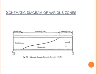

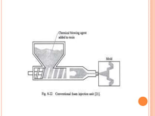
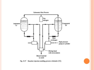
![REACTION INJECTION MOULDING[RIM]
The technique combines two metered ,well mixed
reactive sreams.(urethane)
One stream contains polyether backbone,a catalyst
and a cross linking agent.
Other stream contains has isocynate,blowing agent
ADVANTAGES:
Conducted at low temperature(60-90C) for
polyvinyl.
Processing and preparing takes place
simultaneously.](https://image.slidesharecdn.com/polymerprocessing-141017043933-conversion-gate02/85/Polymer-processing-35-320.jpg)
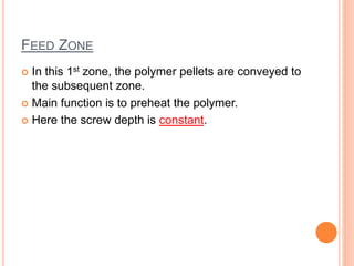
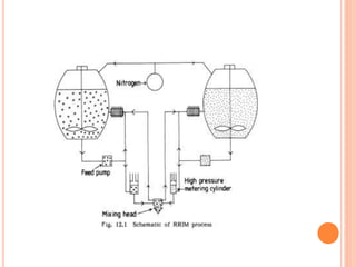
![REINFORCED INJECTION MOULDING[RRIM]
It is an extesion of RIM where there is inclusion of a
reinforced glass fibre.
Here ,two fast reacting liquid streams are precisely
metered and mixed using high pressure
impingement mixing with polymer blowing agents.
ADVANTAGES:
Moulding ranges from rubbery flexible to semi
flexible materials to rigid unyielding products by
suitable deformation of reactants.
Internal mould pressures are low.](https://image.slidesharecdn.com/polymerprocessing-141017043933-conversion-gate02/85/Polymer-processing-37-320.jpg)
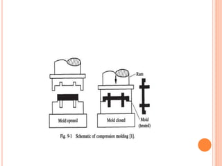
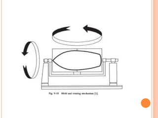
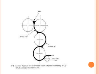
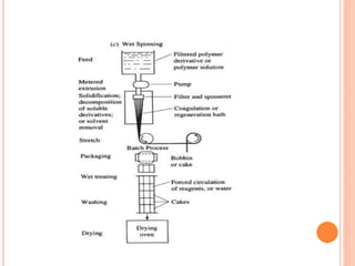

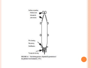
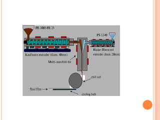
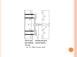
The document discusses various polymer processing techniques. It begins by explaining that the main goal of polymer processing is to produce usable objects and lists the necessary parameters for processing including flow, heat transfer, mass transfer, and chemical reactions. It then focuses on extrusion, describing it as shaping material by forcing it through a die. Various extrusion techniques are discussed including single screw extrusion, twin screw extrusion, blown film extrusion, co-extrusion, and injection molding. Other processing methods summarized include thermoforming, vacuum forming, rotational molding, calendering, and spinning.


![[Deck] What's New in Spark-Iceberg Integration via DSV2.pptx](https://cdn.slidesharecdn.com/ss_thumbnails/deckwhatsnewinspark-icebergintegrationviadsv2-260210005337-25955b12-thumbnail.jpg?width=640&height=640&fit=bounds)


