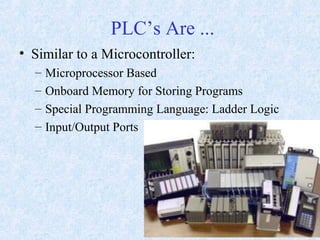
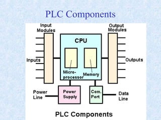
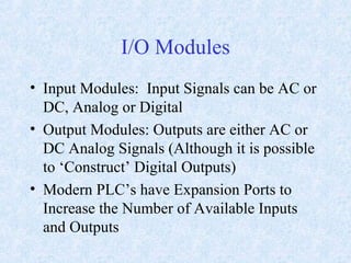
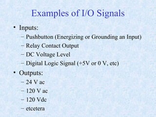
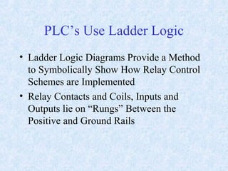
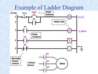
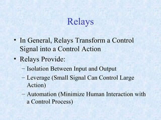
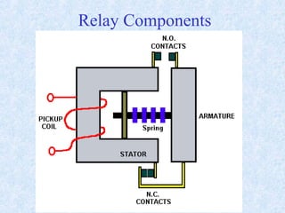
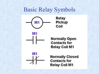
Programmable Logic Controllers
By
Raj Nayak
PLC’s Are ...
• Similar to a Microcontroller:
– Microprocessor Based
– Onboard Memory for Storing Programs
– Special Programming Language: Ladder Logic
– Input/Output Ports
PLC’s Are...
• Dissimilar to Microcontrollers:
– Intended for Industrial Applications
– I/O Designed to interface with Control Relays
– Emphasis on Maximum Reliability
PLC’s
• Widely Applied in Every Industry
• Were Developed to Simplify the
Implementation of Control Automation
Systems in Plants and Assembly Lines
• Designed to Minimize the Number of
Control Relays in a Process and Maximize
the Ways Relays can be Used
• First Applied to Automobile Industry in the
Late 1960’s
• Flexible, Reliable and Low Cost
PLC Components
I/O Modules
• Input Modules: Input Signals can be AC or
DC, Analog or Digital
• Output Modules: Outputs are either AC or
DC Analog Signals (Although it is possible
to ‘Construct’ Digital Outputs)
• Modern PLC’s have Expansion Ports to
Increase the Number of Available Inputs
and Outputs
Examples of I/O Signals
• Inputs:
– Pushbutton (Energizing or Grounding an Input)
– Relay Contact Output
– DC Voltage Level
– Digital Logic Signal (+5V or 0 V, etc)
• Outputs:
– 24 V ac
– 120 V ac
– 120 Vdc
– etcetera
PLC’s Use Ladder Logic
• Ladder Logic Diagrams Provide a Method
to Symbolically Show How Relay Control
Schemes are Implemented
• Relay Contacts and Coils, Inputs and
Outputs lie on “Rungs” Between the
Positive and Ground Rails
Example of Ladder Diagram
Relays
• In General, Relays Transform a Control
Signal into a Control Action
• Relays Provide:
– Isolation Between Input and Output
– Leverage (Small Signal Can Control Large
Action)
– Automation (Minimize Human Interaction with
a Control Process)
Relay Components
Basic Relay Symbols
Relay Applications
• Relays can be Designed to Perform Many
Functions
– Detect Out of Limit Conditions on Voltages
and Currents
– Start Motors
– Prevent Motors from Over Heating
– Control Assembly Lines
– Adjust Lighting
PLC Timers and Motor
Protection
Industrial Communications
• RS-422 (EIA 422): Asynchronous Serial
Communications , similar in many respects
to RS-232
• Faster (up to 100 Kbps) than RS-232
• Better Noise Immunity
– Differential (Balanced signal) Protocol
– Makes use of Twisted Pair lines - 1 pair for
transmit, one pair for receive (4 Lines vs. 3)
EIA-422 Basics
• Can be 1 Master Transmitter feeding up to
10 Slave Receivers
• Can be Peer-to-Peer, like RS-232
• Data is sent and received via Differential
Ports - Common Mode Rejection (Noise
common to both inputs is attenuated)
• Twisted Pair also reduces EMI at low cost
Common Mode Rejection
EIA 485 (RS-485)
• More Modern, Faster and Flexible (supports TCP/IP)
• Since it uses a differential balanced line over twisted
pair (like EIA-422), it can span relatively large
distances (up to 4000 feet or just over 1200 metres).
• In contrast to EIA-422, which has a single driver
circuit which cannot be switched off, EIA-485 drives
need to be put in transmit mode explicitly by
asserting a signal to the driver. This allows EIA-485
to implement linear topologies using only two lines.
IEEE 802.3 (Ethernet)
• Star Topology (Hub and spokes)
• Standard for computer networks since the
1990’s
• Becoming more and more popular in
Industrial settings
• Uses twisted pair data cables terminated in
8P8C (sometimes incorrectly called RJ45)
modular plugs, wired according to TIA/EIA-
568-B
Twisted Pair Cables
• Twisting a pair of wires that act as a communication
channel will:
– Minimize the loop area between the pair (minimize the
self-inductance and capacitance)
– Which in turn tends to cancel out much of the
electromagnetic interference from external sources and
crosstalk from adjacent pairs
– Improve the efficiency of the channel
PLC Special Features
• Time Delay Relays
• Counter Relays
• Special Functions
• User Defined Functions
• Special Bits
Time Delay Relays
• When TD Relay Pick-Up Coil is Energized,
a Delay is Initiated
• Normally Open Contacts Wait to Close
until Delay is Completed
• Normally Closed Contacts Wait to Open
until Delay is Completed
• Very Useful for Creating a Sequence of
Control Events
Time Delay Symbol
• Can be Constructed With or Without a
Reset Input
Making Use of Delays
• Delay Motor Start While Alarm Sounds for
Safety
Counters
• Counter Relays must “Count” a pre-
determined number of events before
changing contact status
• Can Count Up (UpCounter) or Count Down
(DownCounter)
• e.g. An UpCounter is set to 8 and is
programmed to detect every occurrence of a
5 Volt pulse. When it has detected 8 such
occurrences, the NO Contacts close and the
NC contacts open.
• Great for making Real-Time Clocks, etc
Special Functions
• Modern PLCs can perform many Math and
Logic Functions without additional Ladder
Logic Programming
– Differentiation, Integration
– +, -, *, /
– Boolean Logic Functions (AND, NOT, OR)
– Master Control Functions (Reset, etc)
Motor Protection
• Essential Part of Motor Control
• Protect against:
– Under Voltage
– Under Frequency (AC Machines Only)
– Over Current
– Over Heating
– Over Speed
– Over Load
Motor Protection Schemes
• Incorporated Directly in Ladder Logic
Control Schemes
References
• Skvarenina/DeWitt, Electrical Power and
Controls, Pearson-Prentice Hall, 2004

PLC lecture by raj nayak

  • 1.
  • 2.
    PLC’s Are ... •Similar to a Microcontroller: – Microprocessor Based – Onboard Memory for Storing Programs – Special Programming Language: Ladder Logic – Input/Output Ports
  • 3.
    PLC’s Are... • Dissimilarto Microcontrollers: – Intended for Industrial Applications – I/O Designed to interface with Control Relays – Emphasis on Maximum Reliability
  • 4.
    PLC’s • Widely Appliedin Every Industry • Were Developed to Simplify the Implementation of Control Automation Systems in Plants and Assembly Lines • Designed to Minimize the Number of Control Relays in a Process and Maximize the Ways Relays can be Used • First Applied to Automobile Industry in the Late 1960’s • Flexible, Reliable and Low Cost
  • 5.
  • 7.
    I/O Modules • InputModules: Input Signals can be AC or DC, Analog or Digital • Output Modules: Outputs are either AC or DC Analog Signals (Although it is possible to ‘Construct’ Digital Outputs) • Modern PLC’s have Expansion Ports to Increase the Number of Available Inputs and Outputs
  • 8.
    Examples of I/OSignals • Inputs: – Pushbutton (Energizing or Grounding an Input) – Relay Contact Output – DC Voltage Level – Digital Logic Signal (+5V or 0 V, etc) • Outputs: – 24 V ac – 120 V ac – 120 Vdc – etcetera
  • 9.
    PLC’s Use LadderLogic • Ladder Logic Diagrams Provide a Method to Symbolically Show How Relay Control Schemes are Implemented • Relay Contacts and Coils, Inputs and Outputs lie on “Rungs” Between the Positive and Ground Rails
  • 10.
  • 11.
    Relays • In General,Relays Transform a Control Signal into a Control Action • Relays Provide: – Isolation Between Input and Output – Leverage (Small Signal Can Control Large Action) – Automation (Minimize Human Interaction with a Control Process)
  • 12.
  • 13.
  • 14.
    Relay Applications • Relayscan be Designed to Perform Many Functions – Detect Out of Limit Conditions on Voltages and Currents – Start Motors – Prevent Motors from Over Heating – Control Assembly Lines – Adjust Lighting
  • 15.
    PLC Timers andMotor Protection
  • 16.
    Industrial Communications • RS-422(EIA 422): Asynchronous Serial Communications , similar in many respects to RS-232 • Faster (up to 100 Kbps) than RS-232 • Better Noise Immunity – Differential (Balanced signal) Protocol – Makes use of Twisted Pair lines - 1 pair for transmit, one pair for receive (4 Lines vs. 3)
  • 17.
    EIA-422 Basics • Canbe 1 Master Transmitter feeding up to 10 Slave Receivers • Can be Peer-to-Peer, like RS-232 • Data is sent and received via Differential Ports - Common Mode Rejection (Noise common to both inputs is attenuated) • Twisted Pair also reduces EMI at low cost
  • 18.
  • 19.
    EIA 485 (RS-485) •More Modern, Faster and Flexible (supports TCP/IP) • Since it uses a differential balanced line over twisted pair (like EIA-422), it can span relatively large distances (up to 4000 feet or just over 1200 metres). • In contrast to EIA-422, which has a single driver circuit which cannot be switched off, EIA-485 drives need to be put in transmit mode explicitly by asserting a signal to the driver. This allows EIA-485 to implement linear topologies using only two lines.
  • 20.
    IEEE 802.3 (Ethernet) •Star Topology (Hub and spokes) • Standard for computer networks since the 1990’s • Becoming more and more popular in Industrial settings • Uses twisted pair data cables terminated in 8P8C (sometimes incorrectly called RJ45) modular plugs, wired according to TIA/EIA- 568-B
  • 21.
    Twisted Pair Cables •Twisting a pair of wires that act as a communication channel will: – Minimize the loop area between the pair (minimize the self-inductance and capacitance) – Which in turn tends to cancel out much of the electromagnetic interference from external sources and crosstalk from adjacent pairs – Improve the efficiency of the channel
  • 22.
    PLC Special Features •Time Delay Relays • Counter Relays • Special Functions • User Defined Functions • Special Bits
  • 23.
    Time Delay Relays •When TD Relay Pick-Up Coil is Energized, a Delay is Initiated • Normally Open Contacts Wait to Close until Delay is Completed • Normally Closed Contacts Wait to Open until Delay is Completed • Very Useful for Creating a Sequence of Control Events
  • 24.
    Time Delay Symbol •Can be Constructed With or Without a Reset Input
  • 25.
    Making Use ofDelays • Delay Motor Start While Alarm Sounds for Safety
  • 26.
    Counters • Counter Relaysmust “Count” a pre- determined number of events before changing contact status • Can Count Up (UpCounter) or Count Down (DownCounter) • e.g. An UpCounter is set to 8 and is programmed to detect every occurrence of a 5 Volt pulse. When it has detected 8 such occurrences, the NO Contacts close and the NC contacts open. • Great for making Real-Time Clocks, etc
  • 27.
    Special Functions • ModernPLCs can perform many Math and Logic Functions without additional Ladder Logic Programming – Differentiation, Integration – +, -, *, / – Boolean Logic Functions (AND, NOT, OR) – Master Control Functions (Reset, etc)
  • 28.
    Motor Protection • EssentialPart of Motor Control • Protect against: – Under Voltage – Under Frequency (AC Machines Only) – Over Current – Over Heating – Over Speed – Over Load
  • 29.
    Motor Protection Schemes •Incorporated Directly in Ladder Logic Control Schemes
  • 30.
    References • Skvarenina/DeWitt, ElectricalPower and Controls, Pearson-Prentice Hall, 2004