Downloaded 1,207 times


![WHY MECHANICAL SEALS
CONVENTIONAL SEALING
CONVENTIONAL SEALING IS BY MEANS
OF GLAND PACKING .THE PROBLEMS
WITH GLAND PACKINGS ARE:
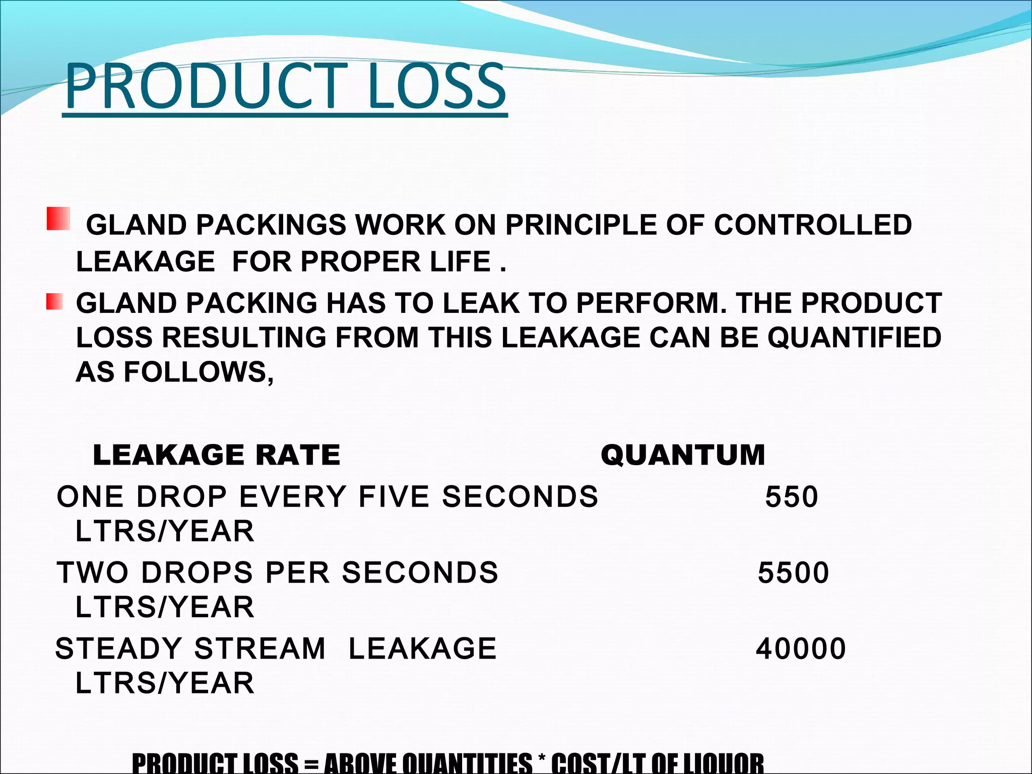
1] PRODUCT LOSS
2] EXCESSIVE WEAR ON SHAFT & SLEEVE
3] FREQUENT ADJUSTMENTS
4] ENERGY LOSS](https://image.slidesharecdn.com/mechanicalsealforpumps-150921014002-lva1-app6892/75/Mechanical-seal-for-pumps-16-2048.jpg)


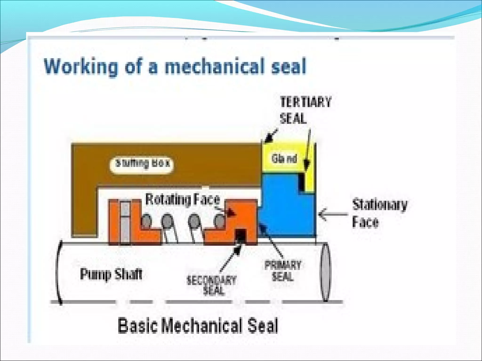
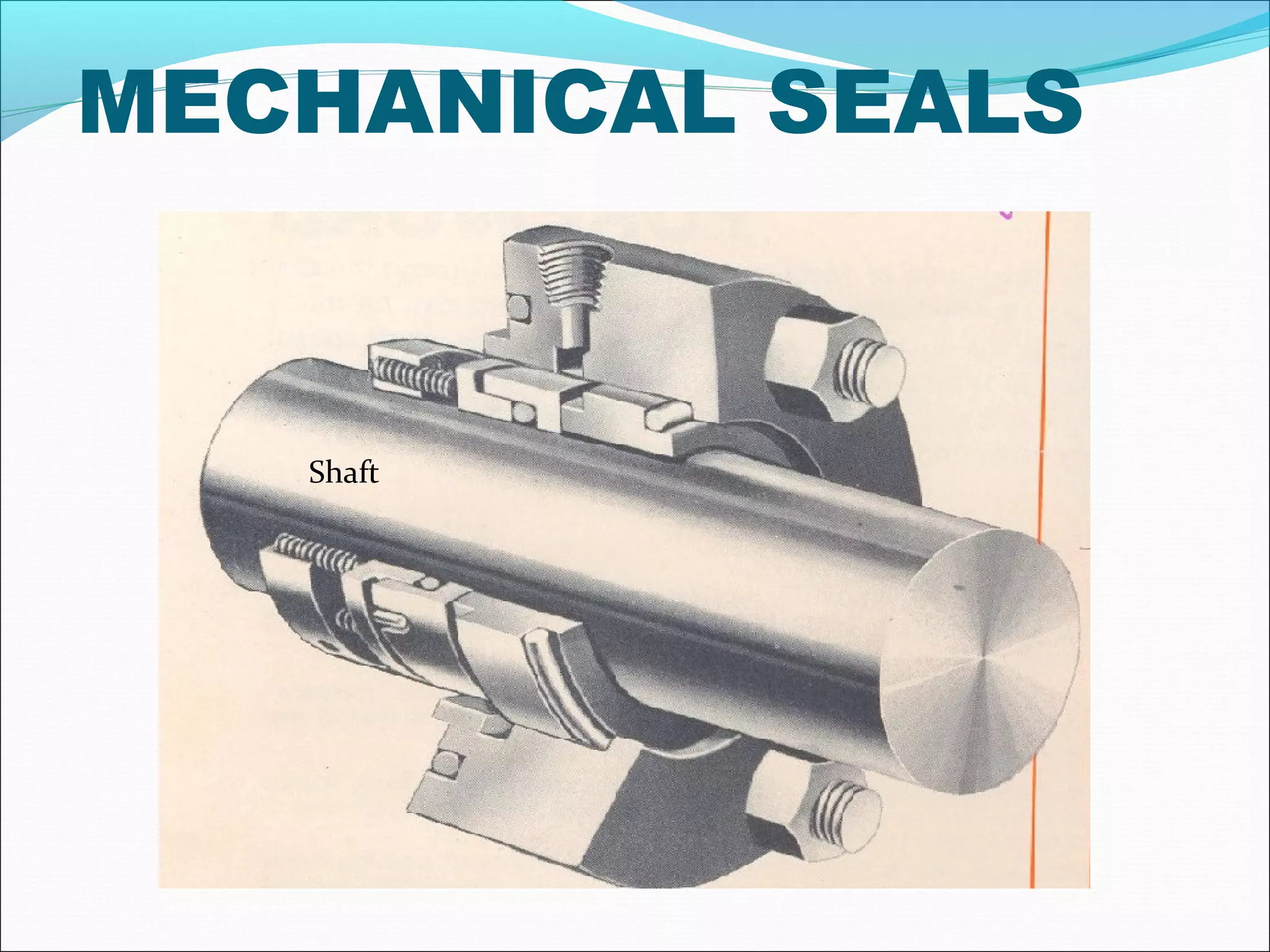
![MECHANICAL SEALS
THE BASIC DESIGN OF A MECHANICAL SEAL
COSISTS OF FOLLOWING ELEMENTS.
1] FLEXIBLY MOUNTED SEAL FACE
2] RIGIDLY MOUNTED SEAL FACE
3] COMPRESSION DEVICE
4] DRIVING MECHANISM
5] SECONDARY SEALS](https://image.slidesharecdn.com/mechanicalsealforpumps-150921014002-lva1-app6892/75/Mechanical-seal-for-pumps-21-2048.jpg)


![CLASSIFICATION OF MECHANICAL
SEALS
1] CLASSIFICATOIN BY DESIGN
A] PUSHER TYPE SEALS
a] Unbalanced seals
1) Single spring type
2) Multi spring type
b] Balanced seals
1) Single spring type
2) Multi spring type
B] NON PUSHER TYPE( BELLOWS TYPE) SEALS
a] Metal bellows seals
b] Teflon bellows seals](https://image.slidesharecdn.com/mechanicalsealforpumps-150921014002-lva1-app6892/75/Mechanical-seal-for-pumps-28-2048.jpg)
![CLASSIFICATION OF MECHANICAL
SEALS
2] CLASSIFICATION BY ARRANGEMENT:
SINGLE SEALS:
A] SINGLE INTERNALLY MOUNTED SEALS.
B] SINGLE EXTERNALLY MOUNTED SEALS
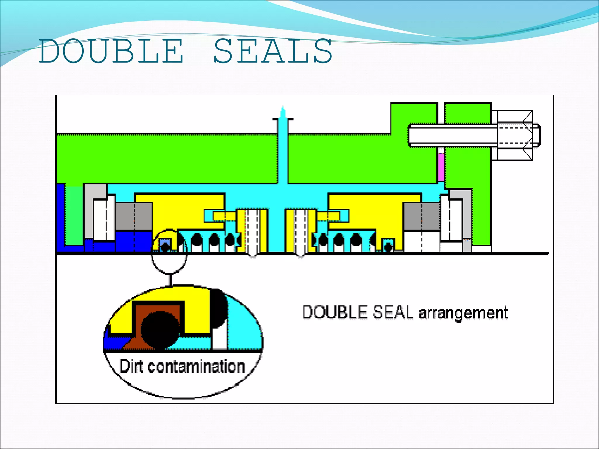
DOUBLE SEALS:
A] BACK TO BACK SEALS
B] FACE TO FACE SEALS
C] TANDEM SEALS](https://image.slidesharecdn.com/mechanicalsealforpumps-150921014002-lva1-app6892/75/Mechanical-seal-for-pumps-29-2048.jpg)


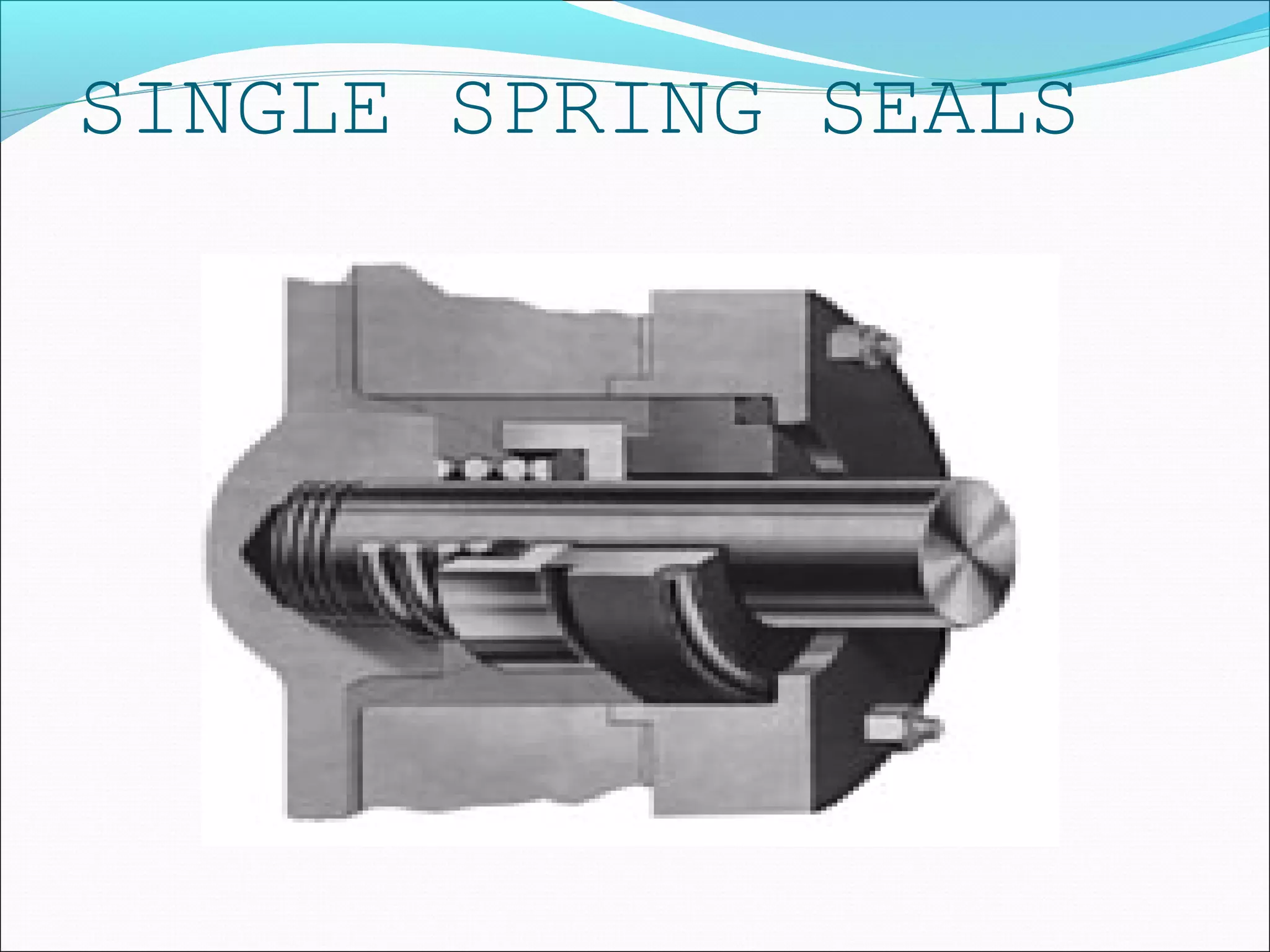
![SINGLE SPRING SEALS
ADVANTAGES:
1] LOW STARTING TORQUE
2] NON-CLOGGING
3] LOW SPRING CONSTANT
LIMITATION:
1] DUE TO SINGLE SPRING THE FACE LOADING IS NOT
ALONG THE PERIPHERY OF THE SEAL
FACES,
[HENCE THESE TYPE OF SEALS ARE NOT
RECOMMENDED FOR VERY HIGH ROTATION SPEEDS]
2]NORMALLY UNIDIRECTIONAL
3] REQUIRE LONG AXIAL SPACE.](https://image.slidesharecdn.com/mechanicalsealforpumps-150921014002-lva1-app6892/75/Mechanical-seal-for-pumps-38-2048.jpg)


![MULTI SPRING SEAL
ADVANTAGES:
1] COMPACT IN COMPARISON WITH SINGLE SPRING SEAL.
2] SPRING LOAD UNIFORM,i.e. UNIFORM FACE LOADING.
3] CAN BE GIVEN FOR HIGHER SPPED THAN SINGLE SPRING.
4] FOR EACH SEAL SIZE DIFFERENT SPRING NOT REQUIRED.
LIMITATION:
1] MORE EXPENSIVE.
2] SPRING CLOGGING POSSIBLE FOR DIRTY LIQUIDS.](https://image.slidesharecdn.com/mechanicalsealforpumps-150921014002-lva1-app6892/75/Mechanical-seal-for-pumps-41-2048.jpg)

![NON PUSHER TYPE SEALS
ADVANTAGES:
1] SEAL HANG UP DUE TO SPRING CLOGGING OR
CLOGGING OF DYNAMIC ELASTOMERS ON THE SHAFT.
NON PUSHER TYPE SEALS DO NOT HAVE DYNAMIC
ELASTOMERS AND HENCE THIS PROBLEM IS AVOIDED.
2] NO SHAFT OR SLEEVE FRETTING AS THERE IS NO
DYNAMIC ELASTOMERS.](https://image.slidesharecdn.com/mechanicalsealforpumps-150921014002-lva1-app6892/75/Mechanical-seal-for-pumps-43-2048.jpg)


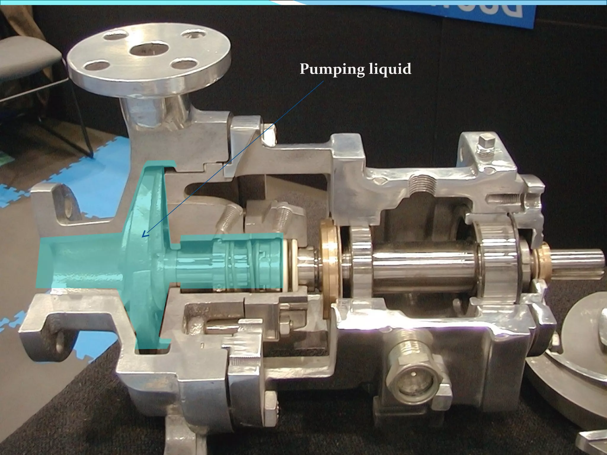
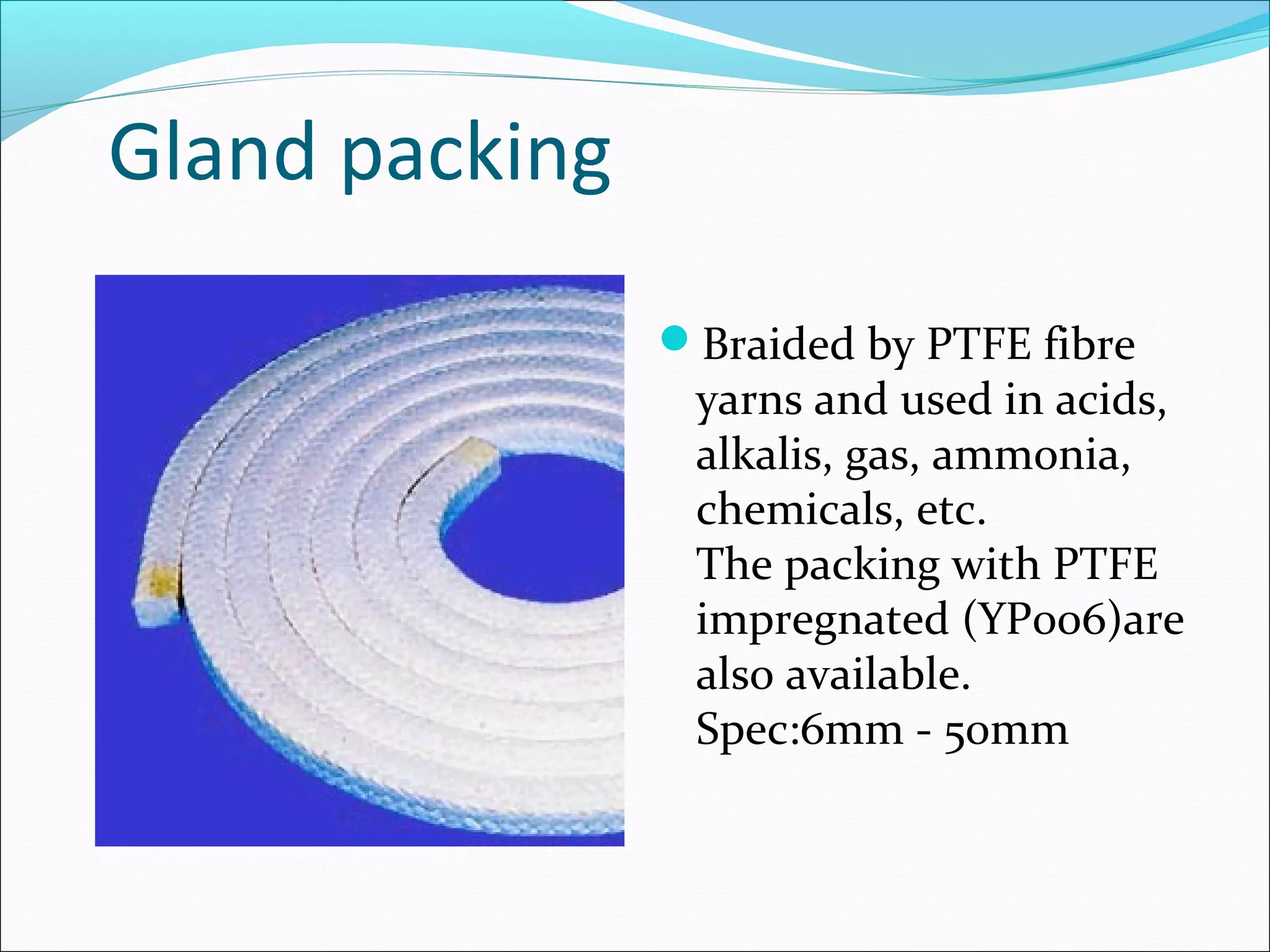
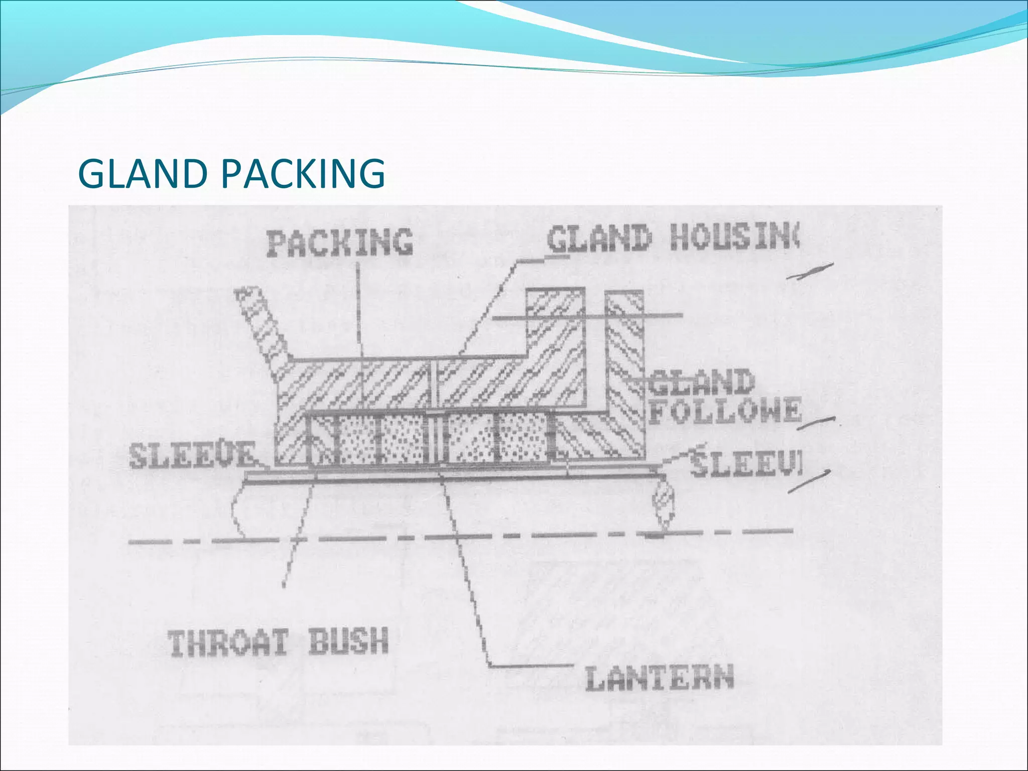
This document discusses mechanical seals which are used to prevent leakage in pumps and other equipment. It describes the need for seals to minimize leakage and prevent toxic fluids from escaping. Both static seals, used between non-moving parts, and dynamic seals, used between moving parts, are covered. Common static seals include gaskets and O-rings, while dynamic seals include gland packings and mechanical contact seals. The document focuses on mechanical seals, explaining their design features such as seal faces, springs, and secondary seals. Different types are classified including single versus multiple spring seals, pusher versus non-pusher seals, and single versus double/tandem arrangements. Materials of construction and operating principles are also summarized.


