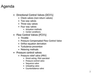
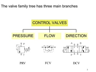
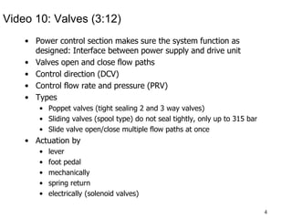
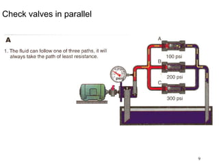
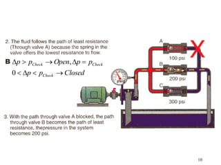
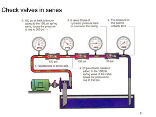
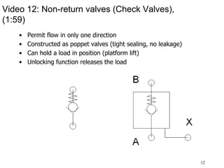
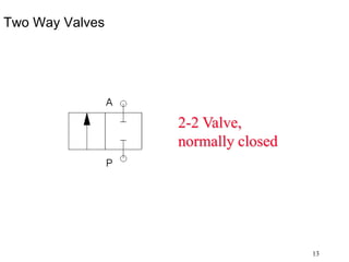
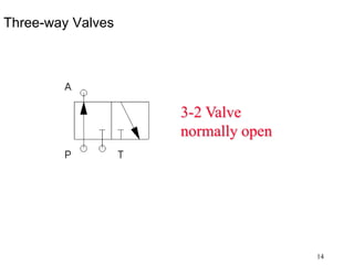
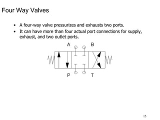
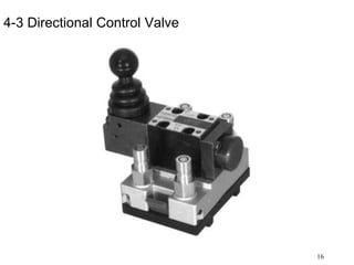
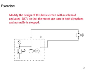
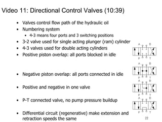
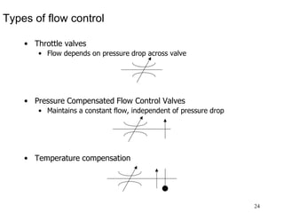
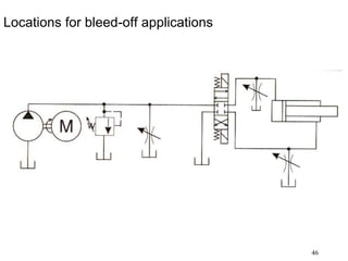
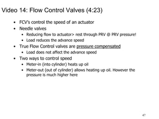
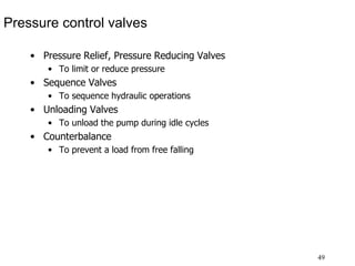
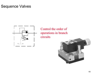
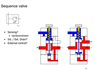
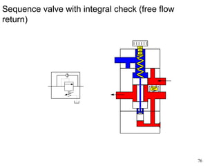
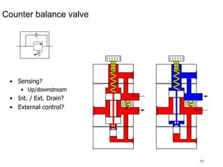
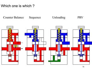
1
TSM363 Fluid Power
Systems
Valves
Tony Grift
Dept. of Agricultural & Biological Engineering
University of Illinois
2
Agenda
• Directional Control Valves (DCV’s)
• Check valves (non-return valves)
• Two way valves
• Three way valves
• Four way valves
• Actuation methods
• Center conditions
• Flow Control Valves (FCV’s)
• Throttle
• Pressure Compensated Flow Control Valve
• Orifice equation derivation
• Turbulence prevention
• Metering methods
• Pressure control valves
• Pressure relief valve (PRV)
• Direct acting, Pilot operated
• Pressure control valve
• Sequence valve
• Unloading valve
• Counterbalance valve
3
The valve family tree has three main branches
PRESSURE FLOW DIRECTION
CONTROL VALVES
FCV
PRV DCV
4
Video 10: Valves (3:12)
• Power control section makes sure the system function as
designed: Interface between power supply and drive unit
• Valves open and close flow paths
• Control direction (DCV)
• Control flow rate and pressure (PRV)
• Types
• Poppet valves (tight sealing 2 and 3 way valves)
• Sliding valves (spool type) do not seal tightly, only up to 315 bar
• Slide valve open/close multiple flow paths at once
• Actuation by
• lever
• foot pedal
• mechanically
• spring return
• electrically (solenoid valves)
5
Directional Control Valves
• Check
• Two way
• Three way
• Four Way
• Proportional (not discussed)
6
JIC Directional Valve Envelope
Each block represents a position. The center condition is
usually drawn with port connections.
A, B : Cylinder/motor connections
P : Pressure port
T : Tank port
7
Numbering system
• 4-3 means 4 ports, 3 positions
• What is the numbering of this valve ?
8
Check Valve
2-1 Valve
Closed
p
p
p
p
Open
p
p
Check
Check
Check









0
,
9
Check valves in parallel
10
Closed
p
p
p
p
Open
p
p
Check
Check
Check









0
,
11
Check valves in series
12
Video 12: Non-return valves (Check Valves),
(1:59)
• Permit flow in only one direction
• Constructed as poppet valves (tight sealing, no leakage)
• Can hold a load in position (platform lift)
• Unlocking function releases the load
13
Two Way Valves
2-2 Valve,
normally closed
14
Three-way Valves
3-2 Valve
normally open
15
Four Way Valves
• A four-way valve pressurizes and exhausts two ports.
• It can have more than four actual port connections for supply,
exhaust, and two outlet ports.
16
4-3 Directional Control Valve
17
Actuation Methods
18
Some examples of symbols
Push buttton, spring return
Push buttton, spring return,
detented
Cam operated, spring return
Solenoid operated, spring return
19
Some examples of symbols
Hydraulically operated, spring return
Hydraulic over electric, spring return
Hydraulic over electric with
manual override , spring return
20
Center conditions
Closed center
Tandem center
Floating center
Open center
21
Exercise
Modify the design of this basic circuit with a solenoid
activated DCV so that the motor can turn in both directions
and normally is stopped.
22
Video 11: Directional Control Valves (10:39)
• Valves control flow path of the hydraulic oil
• Numbering system
• 4-3 means four ports and 3 switching positions
• 3-2 valve used for single acting plunger (ram) cylinder
• 4-3 valves used for double acting cylinders
• Positive piston overlap: all ports blocked in idle
• Negative piston overlap: all ports connected in idle
• Positive and negative in one valve
• P-T connected valve, no pump pressure buildup
• Differential circuit (regenerative) make extension and
retraction speeds the same
23
Flow Control Valves
24
Types of flow control
• Throttle valves
• Flow depends on pressure drop across valve
• Pressure Compensated Flow Control Valves
• Maintains a constant flow, independent of pressure drop
• Temperature compensation
25
2 way Flow control valve
26
Video 6:Bernoulli’s Law & Cavitation (2:10)
• Laminar flow if velocity is low
• Higher flow velocity > lower pressure (Bernoulli’s law)
• Pressure can drop so low it creates bubbles: This can cause
Cavitation or even spontaneous combustion> premature aging
of the oil
• Proper dimensioning can alleviate these effects
27
A pressure drop (across an orifice)only exists if
there is flow: No flow-> No Pressure drop
28
If there is flow, there will be a pressure drop
across the orifice
29
Pressure drop across the orifice is proportional to
the flow rate
2
o o
p
q C A


 
30
Orifice Equation
2
o o
p
q C A


 
 
2
2
3
Determined experimentally 1
Pressure drop proportional to flow rate
Area orifice, adjusted to control pressure and flow rate
Flow rate
Density of fluid (petr
o
o
C
N
p
m
A m
m
q
s

 
  
 
 
 
 
 
 
3
oleum based 850-950
kg
m
 
 
 
31
Flow Through an Orifice:
Laminar Flow Through an Orifice
Turbulent Flow Through an Orifice
32
Turbulence in hydraulics to be avoided at all
times
33
Turbulent and laminar flow
 
 

 
s
Pa
s
m
s
kgm
s
s
m
s
m
m
kg
m
D
s
m
v
m
kg
D
v
N
*
1
viscosity
Absolute
pipe)
of
diameter
(here
dimension
stic
Characteri
Fluid
of
Velocity
fluid
of
Density
1
number
Reynolds
Re
*
*
Re
2
2
3
3



































34
Rule of thumb
Flow
Turbulent
:
Re
4000
area
al
Transition
:
4000
Re
2000
Flow
Laminar
:
2000
Re




35
Homework Pressure Compensated Flow Control
valve
i
p
Hand knob
Outlet port
Inlet port
Manual orifice Am
Automatic orifice Aa
o
p
x
p
q
q
36
Methods of Flow Control
• Meter-In
• By metering the fluid supplied to the actuator
• Meter Out
• By metering the fluid returned from the actuator
• Bleed-off
• By bleeding the excess fluid off to the reservoir
37
Meter-In Circuit
38
Meter-In Circuit
39
Meter In Circuits Do Not Control Runaway
(overrunning) Loads
40
Locations for Meter-In Applications
41
Meter-Out Circuit
42
Locations for Meter-Out Applications
43
Pressure Intensification in Meter-Out Circuits
44
Load pressure adds to intensification pressure in
meter-out circuits
45
Bleed-off circuit
46
Locations for bleed-off applications
47
Video 14: Flow Control Valves (4:23)
• FCV’s control the speed of an actuator
• Needle valves
• Reducing flow to actuator> rest through PRV @ PRV pressure!
• Load reduces the advance speed
• True Flow Control valves are pressure compensated
• Load does not affect the advance speed
• Two ways to control speed
• Meter-in (into cylinder) heats up oil
• Meter-out (out of cylinder) allows heating up oil. However the
pressure is much higher here
48
Pressure Control Valves
49
Pressure control valves
• Pressure Relief, Pressure Reducing Valves
• To limit or reduce pressure
• Sequence Valves
• To sequence hydraulic operations
• Unloading Valves
• To unload the pump during idle cycles
• Counterbalance
• To prevent a load from free falling
50
Video 13: Pressure Control Valves (4:24)
• Pressure relief valve (PRV) limits pressure at the pump, every
hydraulic systems has one
• Pilot operated (much closer to ideal)
• Direct acting
• Dynamic situation (when actuator is moving)
• Static situation is when the cylinder is stalled
• Here the system reaches its highest energy demand!
• Pressure Control Valve (regulator)
• Controls pressure downstream
• Downstream sensing
• Normally open valve
51
Pressure Relief Valve (PRV)
• To limit the maximum pressure at the system input
• Ideal (does not exist), Direct Acting or Pilot Operated
52
A Pressure Relief Valve (PRV) provides overload
protection
• In the symbol there are
• Main pressure lines (solid)
• Sense lines (dashed)
• Spring return
• Adjust arrow
• Direction arrow
• Pressure and Tank connections
53
Some questions about a PRV
• Is this valve normal open or normal closed
• Closed / open, think of a door
• Where is the pressure sensed, upstream or downstream and
why ?
• What is the pressure at the tank port ?
• Why is a PRV adjustable ?
54
Direct Acting Pressure Relief
To Reservoir
System Pressure
55
Direct Acting Pressure Relief
To Reservoir
System Pressure
56
Pilot Operated Pressure Relief Valve (PRV)
57
Balanced Piston PRV:
System pressure below preset pressure
58
System pressure equals preset pressure
59
System Pressure
Flow
through
Relief
Valve
Direct Acting Relief Valve
Pilot Operated
Relief Valve
Cracking Pressure
Full Flow Pressure
Pilot Override in a PRV
60
The need for unloading a pump
A closed center system in idle will dump all oil from a constant
delivery pump to tank through the PRV. This is a complete
waste of energy.
61
Unloading a pump
An unloading valve can directly connect the pump to tank to
save energy
62
Unloading a Pump using Remote Venting on a
balanced piston PRV
63
Unloading Valves (shutoff-counteracting valve)
64
Fig 10.15 Direct acting pressure control valve
65
Fig 10.16 Direct acting pressure control circuit
66
Sequence Valves
Control the order of
operations in branch
circuits
67
Sequence valve using balanced piston concept
A
B
68
First Clamp, then Drill Circuit
69
Counterbalance Valves
Direct Pilot
Optional
Remote Pilot
Unloading valve is set to 10% above the system pressure
required to hold the load.
70
Direct Pilot
Determine the unloading valve setting
required to hold the load?
90 kN
300 cm2
150 cm2
Counterbalance Valves
71
Answer
Pressure required to hold the load:
MPa
p
p
cm
kN
A
F
6
2
150
90
10
10







Set the unloading valve for a 10% higher pressure:
MPa
6
.
6

p
72
Multi purpose Valve
• One valve that can be configured as
• Direct acting PRV
• Sequence valve
• Unloading valve
• Counterbalance valve
73
Direct acting PRV
• Sensing?
• Up/downstream
• Int. / Ext. Drain?
• External control?
74
Unloading valve
• Sensing?
• Up/downstream
• Int. / Ext. Drain?
• External control?
75
Sequence valve
• Sensing?
• Up/downstream
• Int. / Ext. Drain?
• External control?
76
Sequence valve with integral check (free flow
return)
77
Counter balance valve
• Sensing?
• Up/downstream
• Int. / Ext. Drain?
• External control?
78
Which one is which ?
Counter Balance Sequence Unloading PRV
79
TSM363 Fluid Power
Systems
Valves
The End
Dept. of Agricultural & Biological Engineering
University of Illinois

10712832.ppt