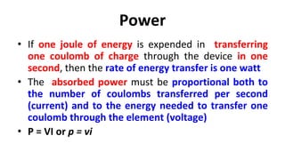
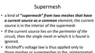
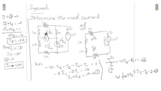
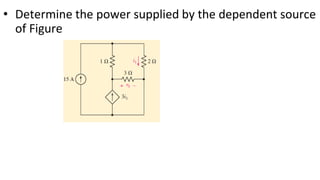
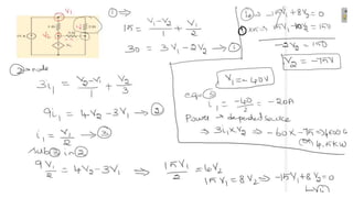
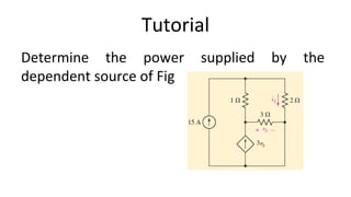
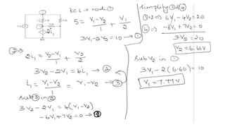
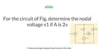
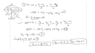
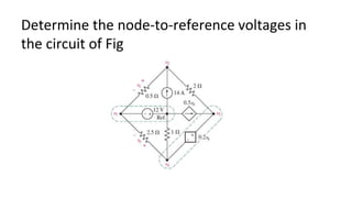
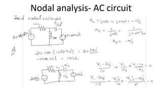
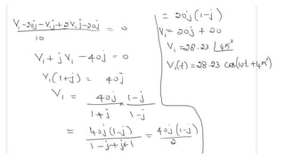
Here are the steps to solve this circuit using the super node method:
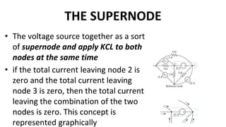
1. Identify the voltage source and nodes connected to it as the super node. In this circuit, the super node contains nodes 1, 2 and the voltage source.
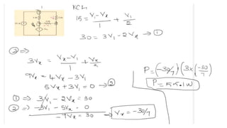
2. Write a KCL equation for the super node equating the sum of currents entering and leaving the super node to 0.
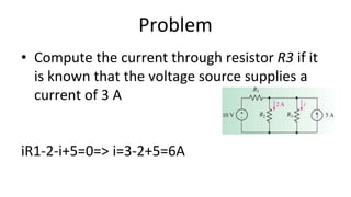
I1 + I2 - 10/5 = 0
3. Replace the branch currents with expressions involving the nodal voltages using Ohm's law.
(V1 - V2)/10 + (V2 - 0)/5 - 10/5 = 0
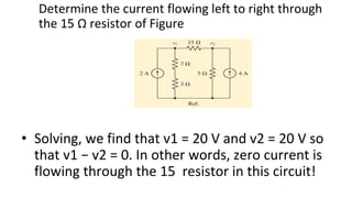
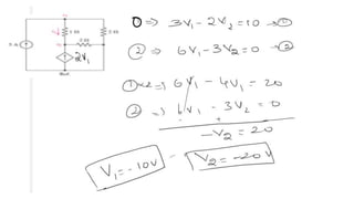
4. Solve the equation to get the nodal voltage V

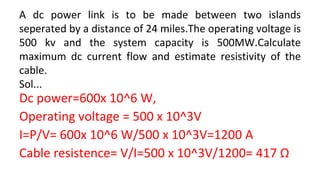


 = −1920 W
p15 = (8) ^2 *(15) = 960 W](https://image.slidesharecdn.com/ece18r201unit1-221227032957-c5db41f8/85/ECE18R201_Unit1-pptx-72-320.jpg)


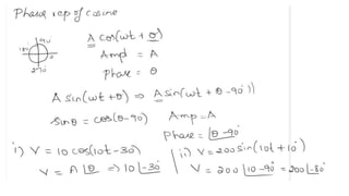
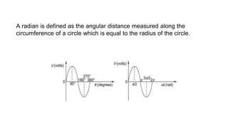
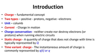
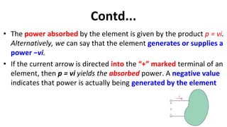
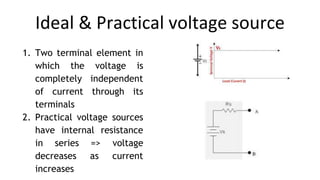
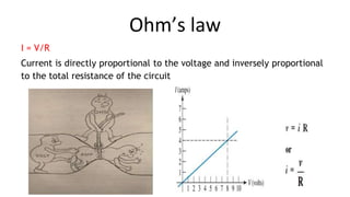
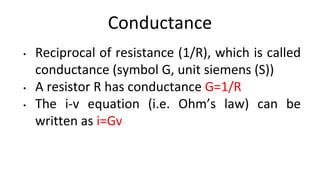
![PHASE RELATION IN A PURE RESISTOR
When a sinusoidal voltage of certain magnitude is applied to a resistor,
a certain amount of sine wave current passes through it. The
voltage/current relation in case of a resistor is linear,
i.e. v (t) = i(t)R
Consider the function
i(t)=Imsin𝜔t=IM[Im ej𝜔t ] or Im∠0o
v(t)= ImR sin𝜔t=Vm sin𝜔t
= IM[Vm ej𝜔t ] or Vm∠0o
Where Vm = ImR
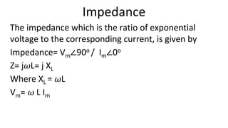
Impedance is defined as the ratio of
voltage to current function](https://image.slidesharecdn.com/ece18r201unit1-221227032957-c5db41f8/85/ECE18R201_Unit1-pptx-128-320.jpg)
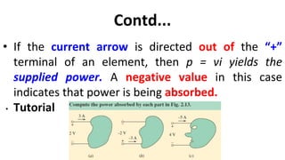
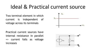
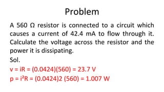
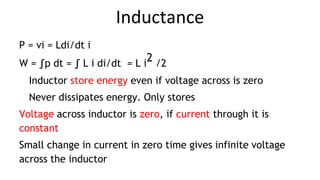
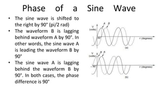
![PHASE RELATION IN A PURE INDUCTOR
v(t)= Ldi/dt
Consider the function
i(t)=Imsin𝜔t=IM[Im ej𝜔t ] or Im∠0o
v(t)= L d(Imsin𝜔t)/dt=L𝜔 Imcos𝜔t =Vmcos𝜔t or Vmsin(𝜔t+90)
= IM[Vm ej(𝜔t+90) ] or Vm∠90o
Vm= 𝜔 L Im =XL Im and ej90 =j=1 ∠90o
Voltage and current are out of phase.
The current lags behind the voltage by 90° in a
pure inductor](https://image.slidesharecdn.com/ece18r201unit1-221227032957-c5db41f8/85/ECE18R201_Unit1-pptx-129-320.jpg)
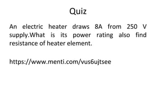
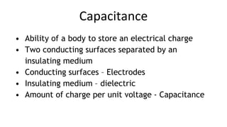
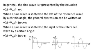
![PHASE RELATION IN A PURE CAPACITOR
v(t)=1/C∫ i(t) dt
Consider the function
i(t)=Imsin𝜔t=IM[Im ej𝜔t ] or Im∠0o
v(t)=1/C ∫Imsin𝜔t dt = 1/𝜔C Im [-cos𝜔t]= Im/𝜔C sin(𝜔t-90)
v(t)= Vmsin(𝜔t-90)=IM[Vm ej(𝜔t-90) ] or Vm∠-90o
Where Vm=Im/𝜔C
Current leads the voltage by 90°
Impedance= Vm∠-90o / Im∠0o
Z= -j/𝜔C= -j XC
Where XC =1/𝜔C](https://image.slidesharecdn.com/ece18r201unit1-221227032957-c5db41f8/85/ECE18R201_Unit1-pptx-131-320.jpg)


![UNIT-I Final (1)[1].pptfgcvhvjgbjhbjgbjhhvhvhvh](https://cdn.slidesharecdn.com/ss_thumbnails/unit-ifinal11-251129122433-e786871d-thumbnail.jpg?width=640&height=640&fit=bounds)


