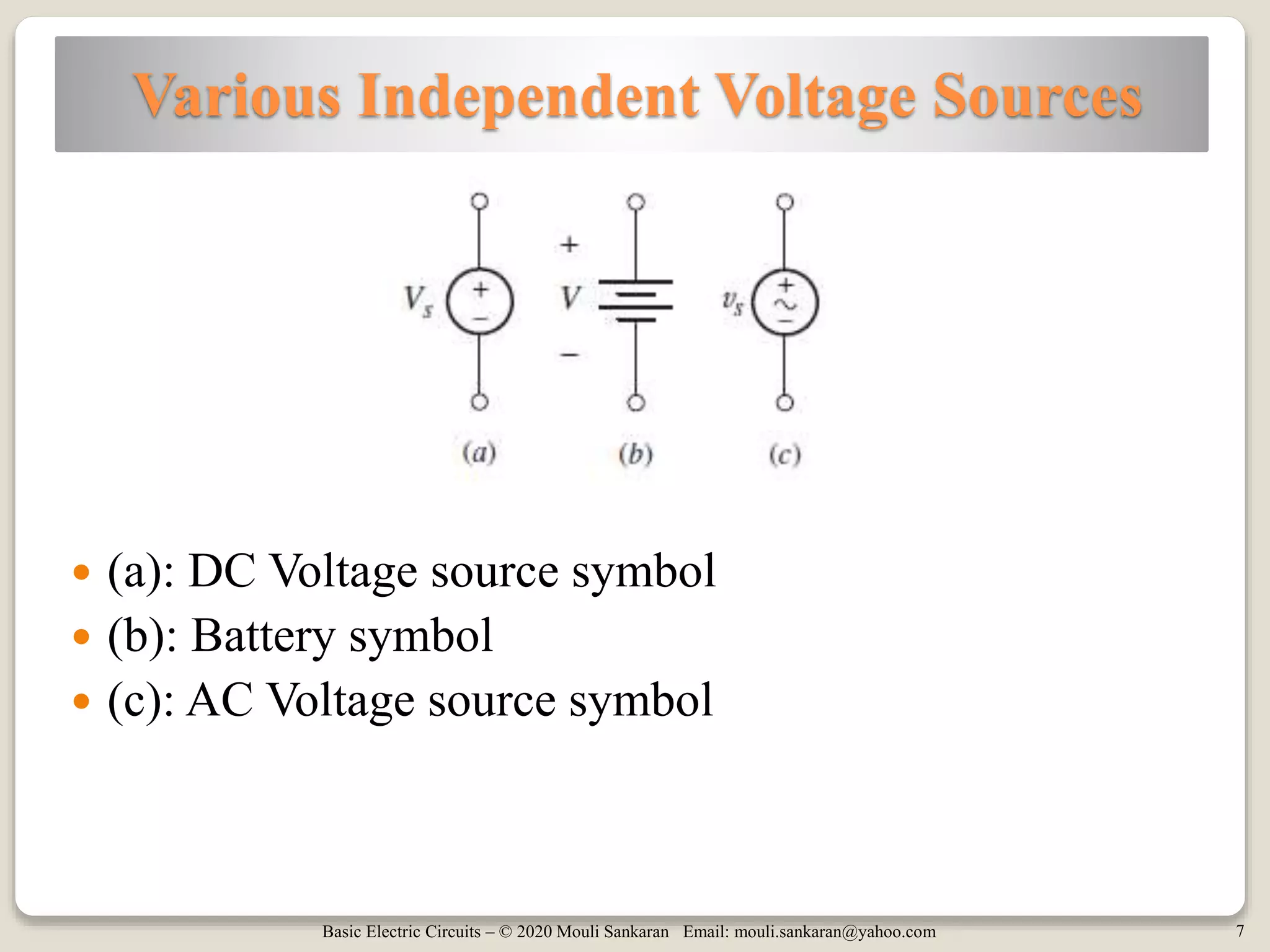
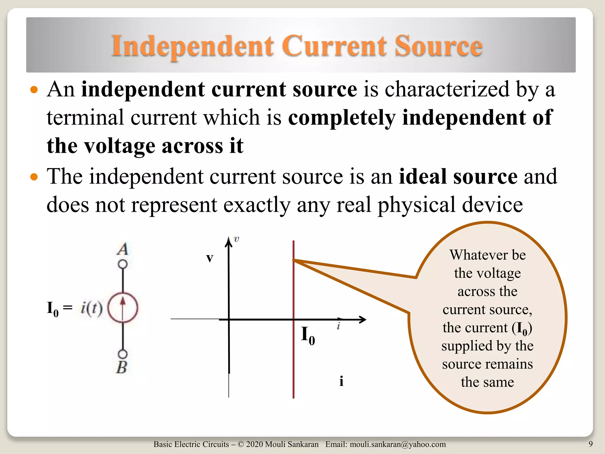
Basic Electric Circuits – © 2020 Mouli Sankaran Email: mouli.sankaran@yahoo.com
Basic Electric Circuits – © 2020 Mouli Sankaran Email: mouli.sankaran@yahoo.com 2
Session 2: Focus
 Simple Circuit Elements
 Independent Voltage Sources
 Independent Current Sources
 Dependent Voltage Sources
◦ Voltage-controlled voltage source
◦ Current-controlled voltage source
 Dependent Current Sources
◦ Current-controlled current source
◦ Voltage-controlled current source
 Solving example problems
 Home Work Problems
Basic Electric Circuits – © 2020 Mouli Sankaran Email: mouli.sankaran@yahoo.com
Simple Circuit Elements
Basic Electric Circuits – © 2020 Mouli Sankaran Email: mouli.sankaran@yahoo.com 4
Simple Circuit Elements Definition
 A simple circuit element is the mathematical model
of a two-terminal electrical device
 Particular model of a real device is derived based on
the experimental data or experience
 Circuit elements are completely characterized by its
voltage-current relationship
 It cannot be subdivided further into other two-
terminal devices
Basic Electric Circuits – © 2020 Mouli Sankaran Email: mouli.sankaran@yahoo.com
Independent Voltage Sources
Basic Electric Circuits – © 2020 Mouli Sankaran Email: mouli.sankaran@yahoo.com 6
Independent Voltage Source
 An independent voltage source is characterized by a
terminal voltage which is completely independent of
the current through it
◦ Or current or power supplied by it
 The independent voltage source is an ideal source and
it does not represent exactly any real physical device
Whatever be
the current
drawn from the
voltage source,
the voltage (V0)
supplied by the
source remains
the same
V0
V0
V0 =
v
i
Basic Electric Circuits – © 2020 Mouli Sankaran Email: mouli.sankaran@yahoo.com 7
Various Independent Voltage Sources
 (a): DC Voltage source symbol
 (b): Battery symbol
 (c): AC Voltage source symbol
Basic Electric Circuits – © 2020 Mouli Sankaran Email: mouli.sankaran@yahoo.com
Independent Current Sources
Basic Electric Circuits – © 2020 Mouli Sankaran Email: mouli.sankaran@yahoo.com 9
Independent Current Source
 An independent current source is characterized by a
terminal current which is completely independent of
the voltage across it
 The independent current source is an ideal source and
does not represent exactly any real physical device
Whatever be
the voltage
across the
current source,
the current (I0)
supplied by the
source remains
the same
I0
I0 =
v
i
Basic Electric Circuits – © 2020 Mouli Sankaran Email: mouli.sankaran@yahoo.com 10
Voltage across Independent Current Sources
 It is a common mistake to view an independent
current source as having zero voltage across its
terminals while providing a fixed current
 In fact, we do not know a priori what the voltage
across a current source will be
◦ It depends entirely on the circuit to which it is connected.
Caution!!
Basic Electric Circuits – © 2020 Mouli Sankaran Email: mouli.sankaran@yahoo.com 11
Use of Mobile Battery
Supplying or absorbing?Supplying or absorbing?
SupplyingAbsorbing
Basic Electric Circuits – © 2020 Mouli Sankaran Email: mouli.sankaran@yahoo.com 12
Independent Sources –
Normally Supply Power
 In their normal mode of operation, independent
sources supply power to the remainder of the circuit.
 However, independent sources may also be
connected into a circuit in such a way that they
absorb power
◦ An example of this is a cell phone battery being connected
to a battery-charging circuit
◦ While the battery is getting charged, it absorbs power from
the charging circuit
◦ After getting charged, when the mobile is functioning
normally, it will be supplying power to the phone
Basic Electric Circuits – © 2020 Mouli Sankaran Email: mouli.sankaran@yahoo.com
Dependent Sources
Basic Electric Circuits – © 2020 Mouli Sankaran Email: mouli.sankaran@yahoo.com 14
Dependent Sources
 In contrast to the independent sources, which produce a
particular voltage or current completely unaffected by
what is happening in the remainder of the circuit
 Dependent sources generate a voltage or current that is
determined by a voltage or current at a specified location
in the circuit
 These sources are very important because they model
the behaviour of many electronic circuit elements
Basic Electric Circuits – © 2020 Mouli Sankaran Email: mouli.sankaran@yahoo.com 15
Dependent Voltage Sources
 (a): Voltage-controlled voltage source
 (b): Current-controlled voltage source
Note: Where K and r are some dimensionless scaling constants
(a) (b)
Basic Electric Circuits – © 2020 Mouli Sankaran Email: mouli.sankaran@yahoo.com 16
Example 1: Dependent Voltage Source
 Which one is a dependent source here?
 What is the type of Dependent source shown on the
top right of the circuit?
 Voltage-controlled voltage source
◦ Depends on the voltage Vx in the circuit, value of K here is 2
Basic Electric Circuits – © 2020 Mouli Sankaran Email: mouli.sankaran@yahoo.com 17
Example 2: Dependent Voltage Source
 What is the type of Dependent source shown on the
right?
 Current-controlled voltage source
◦ Depends on the current Ix in the circuit, value of K here is 4
Basic Electric Circuits – © 2020 Mouli Sankaran Email: mouli.sankaran@yahoo.com 18
Dependent Current Sources
 (a): Current-controlled current source
 (b): Voltage-controlled current source
Note: Where K and g are dimensionless scaling constants
(a) (b)
Basic Electric Circuits – © 2020 Mouli Sankaran Email: mouli.sankaran@yahoo.com 19
Example 3: Dependent Current Source
 What is the type of Dependent source shown on the
right of the circuit?
 Current-controlled current source
◦ Depends on the current Ix in the circuit, value of K here is 2
- +
Basic Electric Circuits – © 2020 Mouli Sankaran Email: mouli.sankaran@yahoo.com 20
Example 4: Dependent Current Source
 What is the type of Dependent source shown on the
right of the circuit?
 Voltage-controlled current source
◦ Depends on the voltage vx in the circuit, value of K here is 0.25
Basic Electric Circuits – © 2020 Mouli Sankaran Email: mouli.sankaran@yahoo.com 21
About Dependent Sources
 As a circle is used to represent independent sources,
a diamond is used to represent dependent sources
◦ They are called as a dependent or controlled sources
 A voltage source which depends on the voltage at
some other part of the circuit may appear strange
 But such sources are invaluable to model many
electronic circuits
Basic Electric Circuits – © 2020 Mouli Sankaran Email: mouli.sankaran@yahoo.com
Solving Example Problems
Basic Electric Circuits – © 2020 Mouli Sankaran Email: mouli.sankaran@yahoo.com 23
Example 1: Solution
 Compute the power supplied or absorbed by the
element 1.
◦ Voltage across the element 1 =
◦ Current through the element 1 =
◦ Does the current enter through +ve or –ve terminal of
◦ element 1?
◦ Power absorbed by the element 1 = p = v * I = 4 * 2 =
+ve terminal
Note: This problem is P 1.34 on
page 22, Figure P 1.34 in the Ref 2
book (by Irwin)
4 V
2 A
8 W
Basic Electric Circuits – © 2020 Mouli Sankaran Email: mouli.sankaran@yahoo.com 24
Example 2: Solution
Note: This problem is E 1.5
on page 12, Figure E 1.5 in
the Ref 2 book (by Irwin)
 Compute the power supplied or absorbed by the
element 1.
◦ Voltage across the element 1 =
◦ Current through the element 1 =
◦ Does the current enter through +ve or –ve terminal of
◦ element 1?
◦ Power absorbed by the element 1 = p = v * I = 4 * 8=
+ve terminal
8 V
4 A
32 W
Basic Electric Circuits – © 2020 Mouli Sankaran Email: mouli.sankaran@yahoo.com 25
Example 3: Solution
 Compute the power supplied by Element 1.
◦ Total power supplied = P18V + P1 + P24V
◦ = - (18 Ix) – (6 Ix) – (24*2) = -24 Ix - 48
◦ Total power absorbed = P2 + P2Ix
◦ = 4* (2 Ix) + 20 * (2 Ix) = 48 Ix
◦ Total power supplied + Total power absorbed = 0
◦ -24 Ix – 48 + 48Ix= 0
◦ 48 = 24 Ix
◦ Ix = 2 A
= 8 A
Result:
Power supplied by
Element 1 = 6 * Ix
= - (6 * 2)
= -12W
20 V
- +
Conservation of
Energy
Note: This problem is P 1.37 on page 23, Figure P
1.37 in the Ref 2 book (by Irwin)
Basic Electric Circuits – © 2020 Mouli Sankaran Email: mouli.sankaran@yahoo.com 26
Example 4: Solution
 Find the power absorbed or supplied by each element.
(left to right)
 P7A = - 8 * 7 = -56 W
 P1 = 8 * 2 = 16 W
 P2 = - 12 * 5 = -60 W
 P3 = 20 * 8 = 160 W
 -vx = 12 V
 vx = -12 V
 P0.25vx = 20 * (0.25vx)
 = 20 * 0.25 * (-12)
 = - 60W
+
-
Current
= -3A
Voltage
= 20 V
Note: This problem is Practice 2.9 on page 20, Figure 2.20 in the Ref 1 book (by Hayt)
2
31
Basic Electric Circuits – © 2020 Mouli Sankaran Email: mouli.sankaran@yahoo.com
Home Work Problems
Basic Electric Circuits – © 2020 Mouli Sankaran Email: mouli.sankaran@yahoo.com 28
S2_HW_Problem_1
 Find the power absorbed or supplied by the elements.
 P20V:
 P1:
 P14V:
-40 W supplied
12 W absorbed
28 W absorbed
Note: This problem is P 1.31 (a) on page 22, Figure P 1.31 in the Ref 2 book (by Irwin)
Basic Electric Circuits – © 2020 Mouli Sankaran Email: mouli.sankaran@yahoo.com 29
S2_HW_Problem_2
 Find the power absorbed or supplied by the elements.
 P4A:
 P1:
 P2Ix :
-64 W supplied
32 W absorbed
32 W absorbed
Note: This problem is P 1.31 (b) on page 22, Figure P 1.31 in the Ref 2 book (by Irwin)
Basic Electric Circuits – © 2020 Mouli Sankaran Email: mouli.sankaran@yahoo.com 30
S2_HW_Problem_3
 Find the unknown power absorbed by Element 1.
 Ix:
 P1:
2 A
24 W
Note: This problem is P 1.36 on page 23, Figure P 1.36 in the Ref 2 book (by Irwin)
Clue: Compute the power supplied or power
Absorbed by each element.
The power supplied will be–ve and
Power absorbed values will be +ve.
Adding them and equating them to zero.
Solve the equation to find Ix. Then compute P1.
Basic Electric Circuits – © 2020 Mouli Sankaran Email: mouli.sankaran@yahoo.com 31
S2_HW_Problem_4
 Find the power supplied/absorbed by the each
elements in the circuit.
Note: This problem is Exercise 29 on page 33, Figure 2.31 in the Ref 1 book (by Hayt)
P2V :-4 W
P3A : 30 W
P4A :40 W
P10V : -50 WP8V :-16 W
Basic Electric Circuits – © 2020 Mouli Sankaran Email: mouli.sankaran@yahoo.com 32
S2_HW_Problem_5
 Find the power absorbed by each element.
 Given: VR = 10V and Vx = 2V
 5Vx :
 PAVx :
 PA :
 P5Vx :
10A
Note: This problem is Exercise 33 on page 33, Figure 2.33 in the Ref 1 book (by Hayt)
-20 W
100 W
-80 W
Basic Electric Circuits – © 2020 Mouli Sankaran Email: mouli.sankaran@yahoo.com 33
Session 2: Summary
 Simple Circuit Elements
 Independent Voltage Sources
 Independent Current Sources
 Dependent Voltage Sources
◦ Voltage-controlled voltage source
◦ Current-controlled voltage source
 Dependent Current Sources
◦ Current-controlled current source
◦ Voltage-controlled current source
 Solving example problems
 Home Work Problems
Basic Electric Circuits – © 2020 Mouli Sankaran Email: mouli.sankaran@yahoo.com 34
References
Ref 1 Ref 2

Basic Electric Circuits Session 2

  • 1.
    Basic Electric Circuits– © 2020 Mouli Sankaran Email: mouli.sankaran@yahoo.com
  • 2.
    Basic Electric Circuits– © 2020 Mouli Sankaran Email: mouli.sankaran@yahoo.com 2 Session 2: Focus  Simple Circuit Elements  Independent Voltage Sources  Independent Current Sources  Dependent Voltage Sources ◦ Voltage-controlled voltage source ◦ Current-controlled voltage source  Dependent Current Sources ◦ Current-controlled current source ◦ Voltage-controlled current source  Solving example problems  Home Work Problems
  • 3.
    Basic Electric Circuits– © 2020 Mouli Sankaran Email: mouli.sankaran@yahoo.com Simple Circuit Elements
  • 4.
    Basic Electric Circuits– © 2020 Mouli Sankaran Email: mouli.sankaran@yahoo.com 4 Simple Circuit Elements Definition  A simple circuit element is the mathematical model of a two-terminal electrical device  Particular model of a real device is derived based on the experimental data or experience  Circuit elements are completely characterized by its voltage-current relationship  It cannot be subdivided further into other two- terminal devices
  • 5.
    Basic Electric Circuits– © 2020 Mouli Sankaran Email: mouli.sankaran@yahoo.com Independent Voltage Sources
  • 6.
    Basic Electric Circuits– © 2020 Mouli Sankaran Email: mouli.sankaran@yahoo.com 6 Independent Voltage Source  An independent voltage source is characterized by a terminal voltage which is completely independent of the current through it ◦ Or current or power supplied by it  The independent voltage source is an ideal source and it does not represent exactly any real physical device Whatever be the current drawn from the voltage source, the voltage (V0) supplied by the source remains the same V0 V0 V0 = v i
  • 7.
    Basic Electric Circuits– © 2020 Mouli Sankaran Email: mouli.sankaran@yahoo.com 7 Various Independent Voltage Sources  (a): DC Voltage source symbol  (b): Battery symbol  (c): AC Voltage source symbol
  • 8.
    Basic Electric Circuits– © 2020 Mouli Sankaran Email: mouli.sankaran@yahoo.com Independent Current Sources
  • 9.
    Basic Electric Circuits– © 2020 Mouli Sankaran Email: mouli.sankaran@yahoo.com 9 Independent Current Source  An independent current source is characterized by a terminal current which is completely independent of the voltage across it  The independent current source is an ideal source and does not represent exactly any real physical device Whatever be the voltage across the current source, the current (I0) supplied by the source remains the same I0 I0 = v i
  • 10.
    Basic Electric Circuits– © 2020 Mouli Sankaran Email: mouli.sankaran@yahoo.com 10 Voltage across Independent Current Sources  It is a common mistake to view an independent current source as having zero voltage across its terminals while providing a fixed current  In fact, we do not know a priori what the voltage across a current source will be ◦ It depends entirely on the circuit to which it is connected. Caution!!
  • 11.
    Basic Electric Circuits– © 2020 Mouli Sankaran Email: mouli.sankaran@yahoo.com 11 Use of Mobile Battery Supplying or absorbing?Supplying or absorbing? SupplyingAbsorbing
  • 12.
    Basic Electric Circuits– © 2020 Mouli Sankaran Email: mouli.sankaran@yahoo.com 12 Independent Sources – Normally Supply Power  In their normal mode of operation, independent sources supply power to the remainder of the circuit.  However, independent sources may also be connected into a circuit in such a way that they absorb power ◦ An example of this is a cell phone battery being connected to a battery-charging circuit ◦ While the battery is getting charged, it absorbs power from the charging circuit ◦ After getting charged, when the mobile is functioning normally, it will be supplying power to the phone
  • 13.
    Basic Electric Circuits– © 2020 Mouli Sankaran Email: mouli.sankaran@yahoo.com Dependent Sources
  • 14.
    Basic Electric Circuits– © 2020 Mouli Sankaran Email: mouli.sankaran@yahoo.com 14 Dependent Sources  In contrast to the independent sources, which produce a particular voltage or current completely unaffected by what is happening in the remainder of the circuit  Dependent sources generate a voltage or current that is determined by a voltage or current at a specified location in the circuit  These sources are very important because they model the behaviour of many electronic circuit elements
  • 15.
    Basic Electric Circuits– © 2020 Mouli Sankaran Email: mouli.sankaran@yahoo.com 15 Dependent Voltage Sources  (a): Voltage-controlled voltage source  (b): Current-controlled voltage source Note: Where K and r are some dimensionless scaling constants (a) (b)
  • 16.
    Basic Electric Circuits– © 2020 Mouli Sankaran Email: mouli.sankaran@yahoo.com 16 Example 1: Dependent Voltage Source  Which one is a dependent source here?  What is the type of Dependent source shown on the top right of the circuit?  Voltage-controlled voltage source ◦ Depends on the voltage Vx in the circuit, value of K here is 2
  • 17.
    Basic Electric Circuits– © 2020 Mouli Sankaran Email: mouli.sankaran@yahoo.com 17 Example 2: Dependent Voltage Source  What is the type of Dependent source shown on the right?  Current-controlled voltage source ◦ Depends on the current Ix in the circuit, value of K here is 4
  • 18.
    Basic Electric Circuits– © 2020 Mouli Sankaran Email: mouli.sankaran@yahoo.com 18 Dependent Current Sources  (a): Current-controlled current source  (b): Voltage-controlled current source Note: Where K and g are dimensionless scaling constants (a) (b)
  • 19.
    Basic Electric Circuits– © 2020 Mouli Sankaran Email: mouli.sankaran@yahoo.com 19 Example 3: Dependent Current Source  What is the type of Dependent source shown on the right of the circuit?  Current-controlled current source ◦ Depends on the current Ix in the circuit, value of K here is 2 - +
  • 20.
    Basic Electric Circuits– © 2020 Mouli Sankaran Email: mouli.sankaran@yahoo.com 20 Example 4: Dependent Current Source  What is the type of Dependent source shown on the right of the circuit?  Voltage-controlled current source ◦ Depends on the voltage vx in the circuit, value of K here is 0.25
  • 21.
    Basic Electric Circuits– © 2020 Mouli Sankaran Email: mouli.sankaran@yahoo.com 21 About Dependent Sources  As a circle is used to represent independent sources, a diamond is used to represent dependent sources ◦ They are called as a dependent or controlled sources  A voltage source which depends on the voltage at some other part of the circuit may appear strange  But such sources are invaluable to model many electronic circuits
  • 22.
    Basic Electric Circuits– © 2020 Mouli Sankaran Email: mouli.sankaran@yahoo.com Solving Example Problems
  • 23.
    Basic Electric Circuits– © 2020 Mouli Sankaran Email: mouli.sankaran@yahoo.com 23 Example 1: Solution  Compute the power supplied or absorbed by the element 1. ◦ Voltage across the element 1 = ◦ Current through the element 1 = ◦ Does the current enter through +ve or –ve terminal of ◦ element 1? ◦ Power absorbed by the element 1 = p = v * I = 4 * 2 = +ve terminal Note: This problem is P 1.34 on page 22, Figure P 1.34 in the Ref 2 book (by Irwin) 4 V 2 A 8 W
  • 24.
    Basic Electric Circuits– © 2020 Mouli Sankaran Email: mouli.sankaran@yahoo.com 24 Example 2: Solution Note: This problem is E 1.5 on page 12, Figure E 1.5 in the Ref 2 book (by Irwin)  Compute the power supplied or absorbed by the element 1. ◦ Voltage across the element 1 = ◦ Current through the element 1 = ◦ Does the current enter through +ve or –ve terminal of ◦ element 1? ◦ Power absorbed by the element 1 = p = v * I = 4 * 8= +ve terminal 8 V 4 A 32 W
  • 25.
    Basic Electric Circuits– © 2020 Mouli Sankaran Email: mouli.sankaran@yahoo.com 25 Example 3: Solution  Compute the power supplied by Element 1. ◦ Total power supplied = P18V + P1 + P24V ◦ = - (18 Ix) – (6 Ix) – (24*2) = -24 Ix - 48 ◦ Total power absorbed = P2 + P2Ix ◦ = 4* (2 Ix) + 20 * (2 Ix) = 48 Ix ◦ Total power supplied + Total power absorbed = 0 ◦ -24 Ix – 48 + 48Ix= 0 ◦ 48 = 24 Ix ◦ Ix = 2 A = 8 A Result: Power supplied by Element 1 = 6 * Ix = - (6 * 2) = -12W 20 V - + Conservation of Energy Note: This problem is P 1.37 on page 23, Figure P 1.37 in the Ref 2 book (by Irwin)
  • 26.
    Basic Electric Circuits– © 2020 Mouli Sankaran Email: mouli.sankaran@yahoo.com 26 Example 4: Solution  Find the power absorbed or supplied by each element. (left to right)  P7A = - 8 * 7 = -56 W  P1 = 8 * 2 = 16 W  P2 = - 12 * 5 = -60 W  P3 = 20 * 8 = 160 W  -vx = 12 V  vx = -12 V  P0.25vx = 20 * (0.25vx)  = 20 * 0.25 * (-12)  = - 60W + - Current = -3A Voltage = 20 V Note: This problem is Practice 2.9 on page 20, Figure 2.20 in the Ref 1 book (by Hayt) 2 31
  • 27.
    Basic Electric Circuits– © 2020 Mouli Sankaran Email: mouli.sankaran@yahoo.com Home Work Problems
  • 28.
    Basic Electric Circuits– © 2020 Mouli Sankaran Email: mouli.sankaran@yahoo.com 28 S2_HW_Problem_1  Find the power absorbed or supplied by the elements.  P20V:  P1:  P14V: -40 W supplied 12 W absorbed 28 W absorbed Note: This problem is P 1.31 (a) on page 22, Figure P 1.31 in the Ref 2 book (by Irwin)
  • 29.
    Basic Electric Circuits– © 2020 Mouli Sankaran Email: mouli.sankaran@yahoo.com 29 S2_HW_Problem_2  Find the power absorbed or supplied by the elements.  P4A:  P1:  P2Ix : -64 W supplied 32 W absorbed 32 W absorbed Note: This problem is P 1.31 (b) on page 22, Figure P 1.31 in the Ref 2 book (by Irwin)
  • 30.
    Basic Electric Circuits– © 2020 Mouli Sankaran Email: mouli.sankaran@yahoo.com 30 S2_HW_Problem_3  Find the unknown power absorbed by Element 1.  Ix:  P1: 2 A 24 W Note: This problem is P 1.36 on page 23, Figure P 1.36 in the Ref 2 book (by Irwin) Clue: Compute the power supplied or power Absorbed by each element. The power supplied will be–ve and Power absorbed values will be +ve. Adding them and equating them to zero. Solve the equation to find Ix. Then compute P1.
  • 31.
    Basic Electric Circuits– © 2020 Mouli Sankaran Email: mouli.sankaran@yahoo.com 31 S2_HW_Problem_4  Find the power supplied/absorbed by the each elements in the circuit. Note: This problem is Exercise 29 on page 33, Figure 2.31 in the Ref 1 book (by Hayt) P2V :-4 W P3A : 30 W P4A :40 W P10V : -50 WP8V :-16 W
  • 32.
    Basic Electric Circuits– © 2020 Mouli Sankaran Email: mouli.sankaran@yahoo.com 32 S2_HW_Problem_5  Find the power absorbed by each element.  Given: VR = 10V and Vx = 2V  5Vx :  PAVx :  PA :  P5Vx : 10A Note: This problem is Exercise 33 on page 33, Figure 2.33 in the Ref 1 book (by Hayt) -20 W 100 W -80 W
  • 33.
    Basic Electric Circuits– © 2020 Mouli Sankaran Email: mouli.sankaran@yahoo.com 33 Session 2: Summary  Simple Circuit Elements  Independent Voltage Sources  Independent Current Sources  Dependent Voltage Sources ◦ Voltage-controlled voltage source ◦ Current-controlled voltage source  Dependent Current Sources ◦ Current-controlled current source ◦ Voltage-controlled current source  Solving example problems  Home Work Problems
  • 34.
    Basic Electric Circuits– © 2020 Mouli Sankaran Email: mouli.sankaran@yahoo.com 34 References Ref 1 Ref 2