Download to read offline


1) The document provides an introduction to fundamental concepts in electrical engineering, including the classification of electrical systems, units of measurement, and basic circuit elements. 2) It describes the five main classifications of electrical systems: communication, computer, control, power, and signal processing systems. 3) The key concepts of charge, current, voltage, power, and energy are defined using standard SI units, and their relationships are expressed through mathematical equations. 4) The two main types of circuit elements - passive (resistors, capacitors, inductors) and active (sources) - are introduced, along with examples of independent and dependent sources.


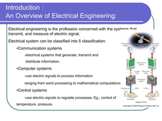
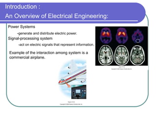
![UNIT-I Final (1)[1].pptfgcvhvjgbjhbjgbjhhvhvhvh](https://cdn.slidesharecdn.com/ss_thumbnails/unit-ifinal11-251129122433-e786871d-thumbnail.jpg?width=640&height=640&fit=bounds)