1
Electric Circuits
Circuit Elements
QiXuan
Ghangzhi Building(广知楼) C323
I will be in the office on Monday, Wednesday, and Friday
Zhejiang University of Technology
September 2015
2.
Structure
• Voltage
and
Current
Sources
• Electrical
Resistance
(Ohm’s
Law)
• Construc<on
of
a
Circuit
Model
• Kirchhoff’s
Laws
• Analysis
of
a
Circuit
Containing
Dependent
Source
2
Electric Circuits
3.
Circuit
Elements
• When
we
speak
of
Circuit
Elements,
It
is
important
to
differen<ate
between
the
physical
device
itself
and
the
mathema<cal
model
which
we
will
use
to
analyze
its
behavior
in
a
circuit.
• We
will
use
the
expression
circuit
element
to
refer
to
the
mathema&cal
model.
• All
the
simple
circuit
elements
that
we
will
consider
can
be
classified
according
to
the
rela<onship
of
current
through
the
element
to
the
voltage
across
the
element.
Electric Circuits 3
4.
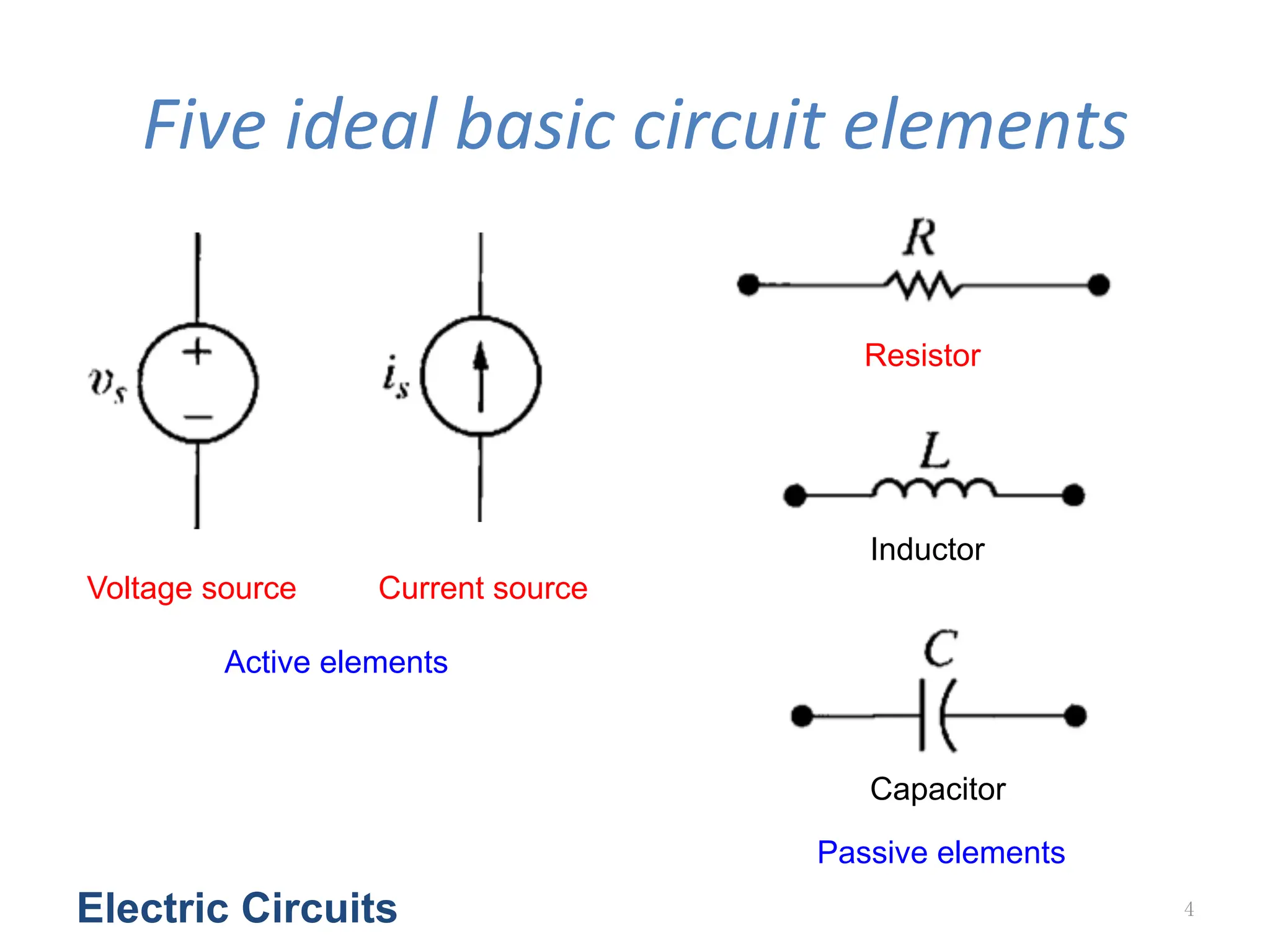
Five
ideal
basic
circuit
elements
Electric Circuits 4
Voltage source Current source
Resistor
Capacitor
Inductor
Active elements
Passive elements
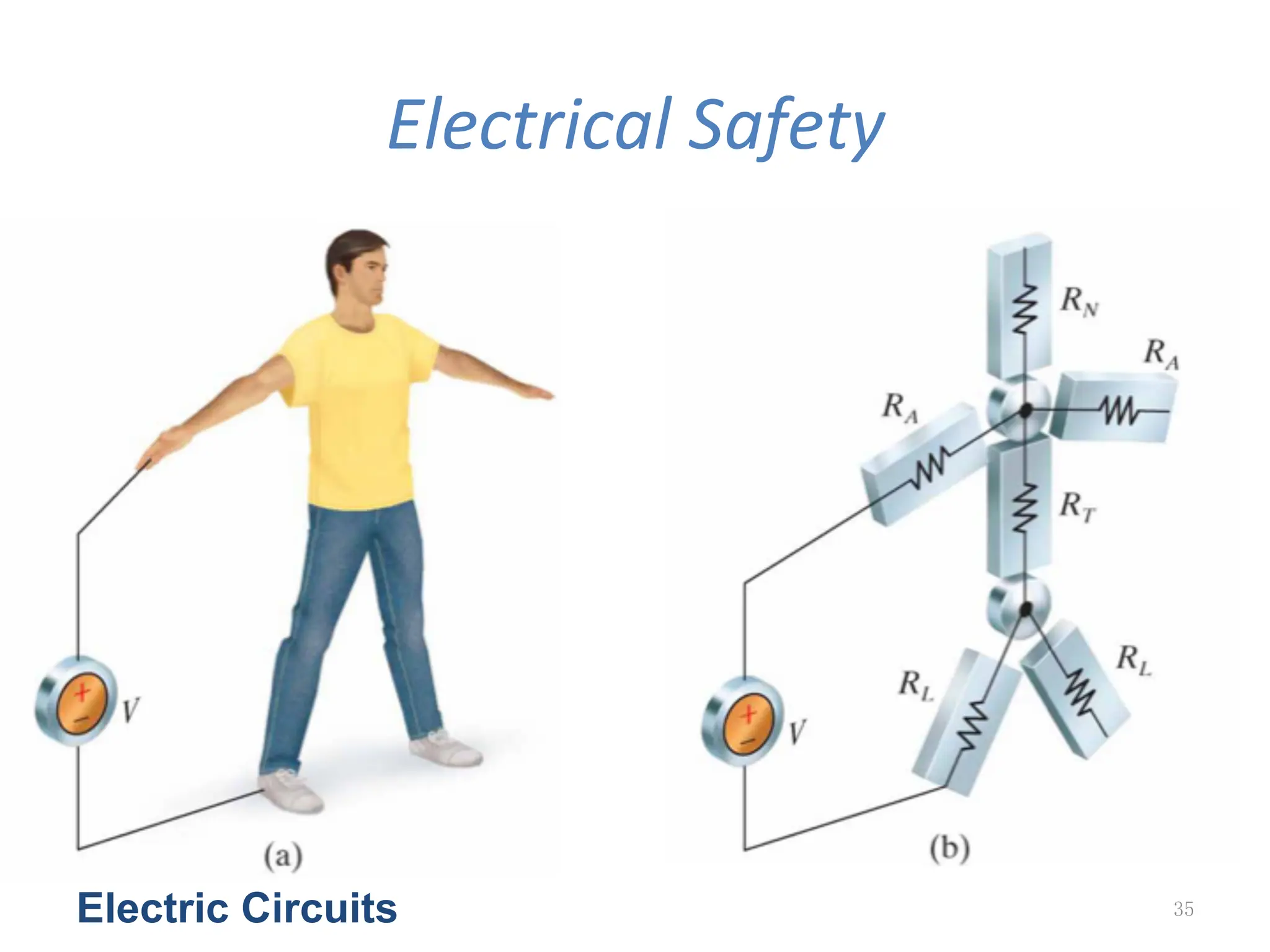
5.
Electrical
safety
Electric Circuits5
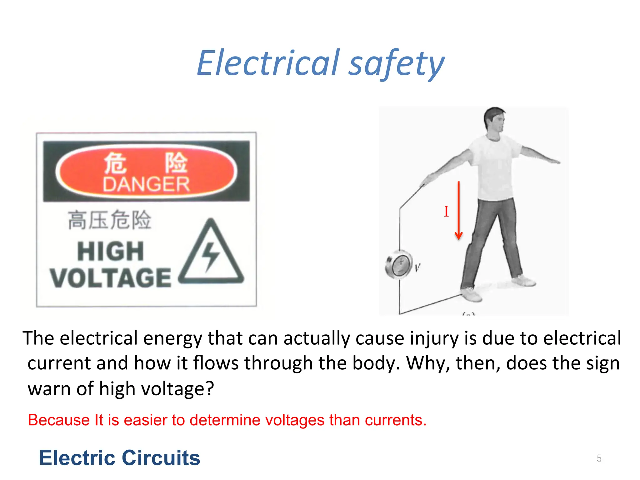
The
electrical
energy
that
can
actually
cause
injury
is
due
to
electrical
current
and
how
it
flows
through
the
body.
Why,
then,
does
the
sign
warn
of
high
voltage?
I
Because It is easier to determine voltages than currents.
6.
Voltage
and
Current
Sources
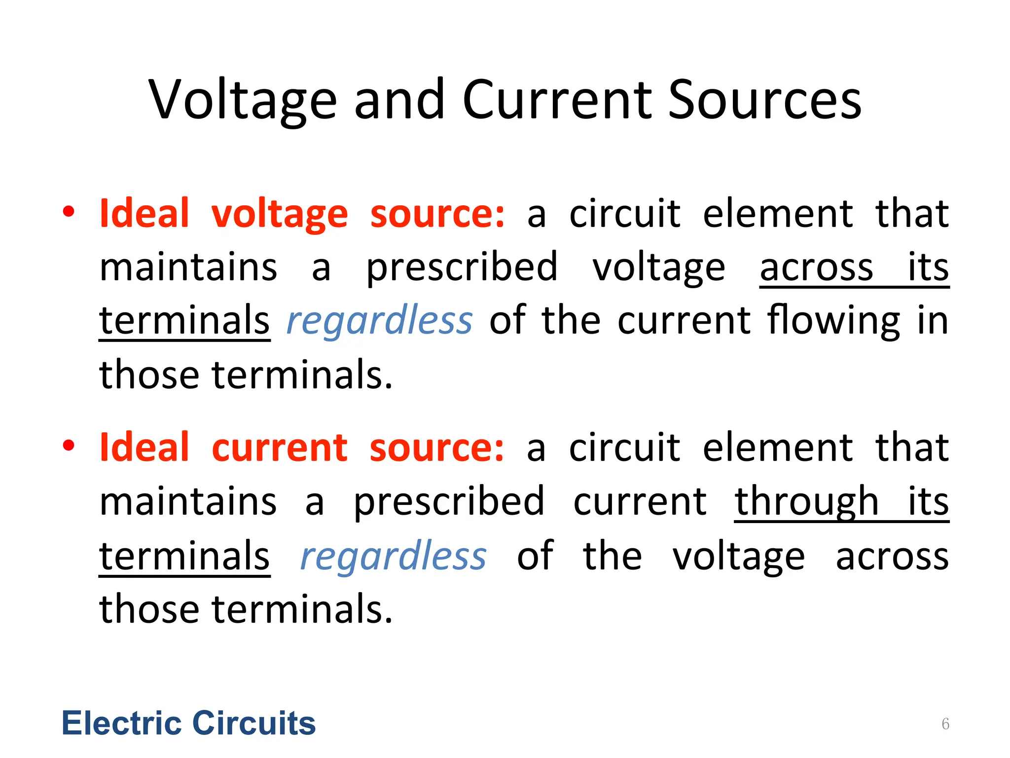
• Ideal
voltage
source:
a
circuit
element
that
maintains
a
prescribed
voltage
across
its
terminals
regardless
of
the
current
flowing
in
those
terminals.
• Ideal
current
source:
a
circuit
element
that
maintains
a
prescribed
current
through
its
terminals
regardless
of
the
voltage
across
those
terminals.
Electric Circuits 6
7.
Independent
Sources
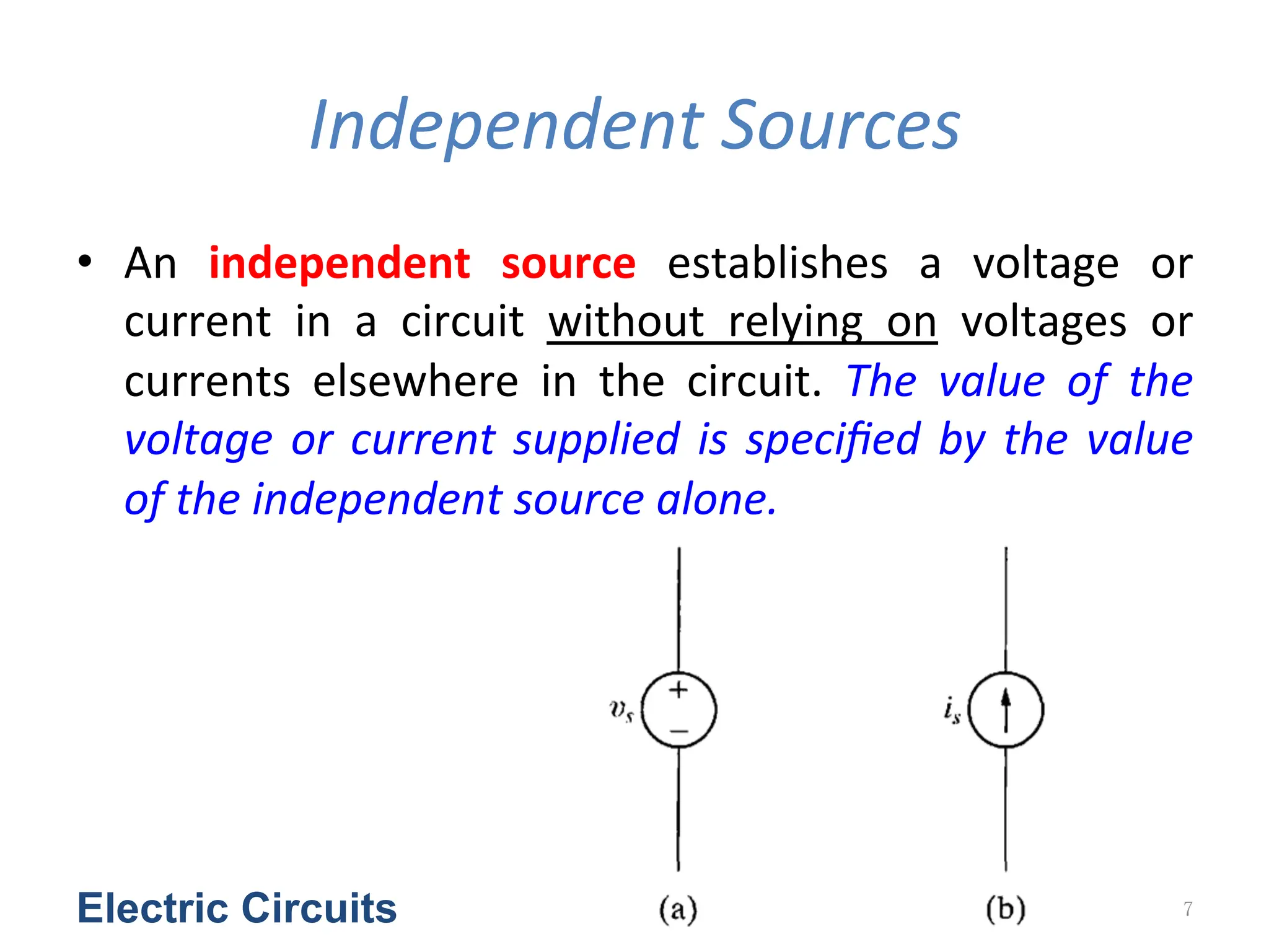
• An
independent
source
establishes
a
voltage
or
current
in
a
circuit
without
relying
on
voltages
or
currents
elsewhere
in
the
circuit.
The
value
of
the
voltage
or
current
supplied
is
specified
by
the
value
of
the
independent
source
alone.
Electric Circuits 7
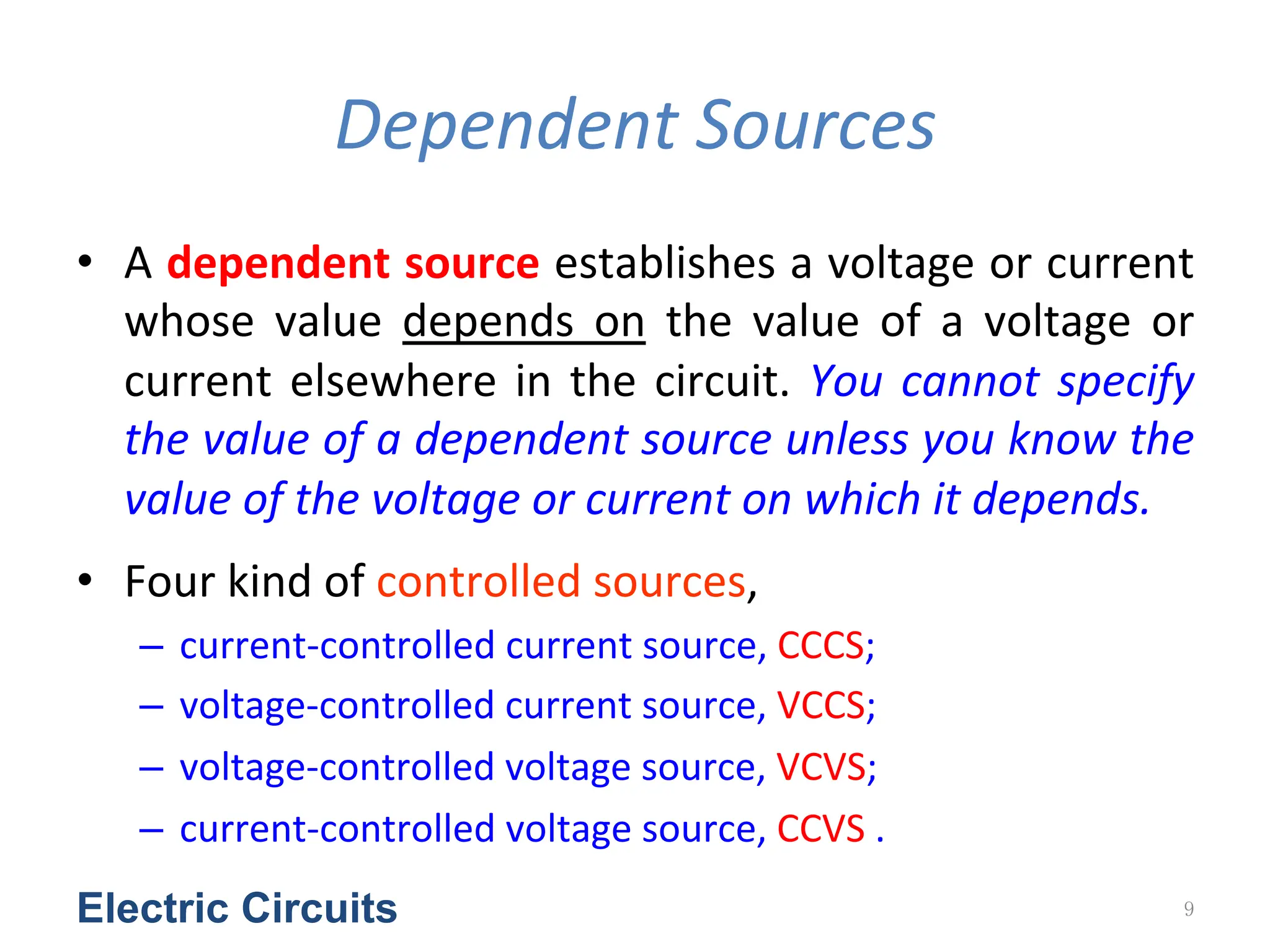
Dependent
Sources
• A
dependent
source
establishes
a
voltage
or
current
whose
value
depends
on
the
value
of
a
voltage
or
current
elsewhere
in
the
circuit.
You
cannot
specify
the
value
of
a
dependent
source
unless
you
know
the
value
of
the
voltage
or
current
on
which
it
depends.
• Four
kind
of
controlled
sources,
– current-‐controlled
current
source,
CCCS;
– voltage-‐controlled
current
source,
VCCS;
– voltage-‐controlled
voltage
source,
VCVS;
– current-‐controlled
voltage
source,
CCVS
.
Electric Circuits 9
10.
Electric Circuits 10
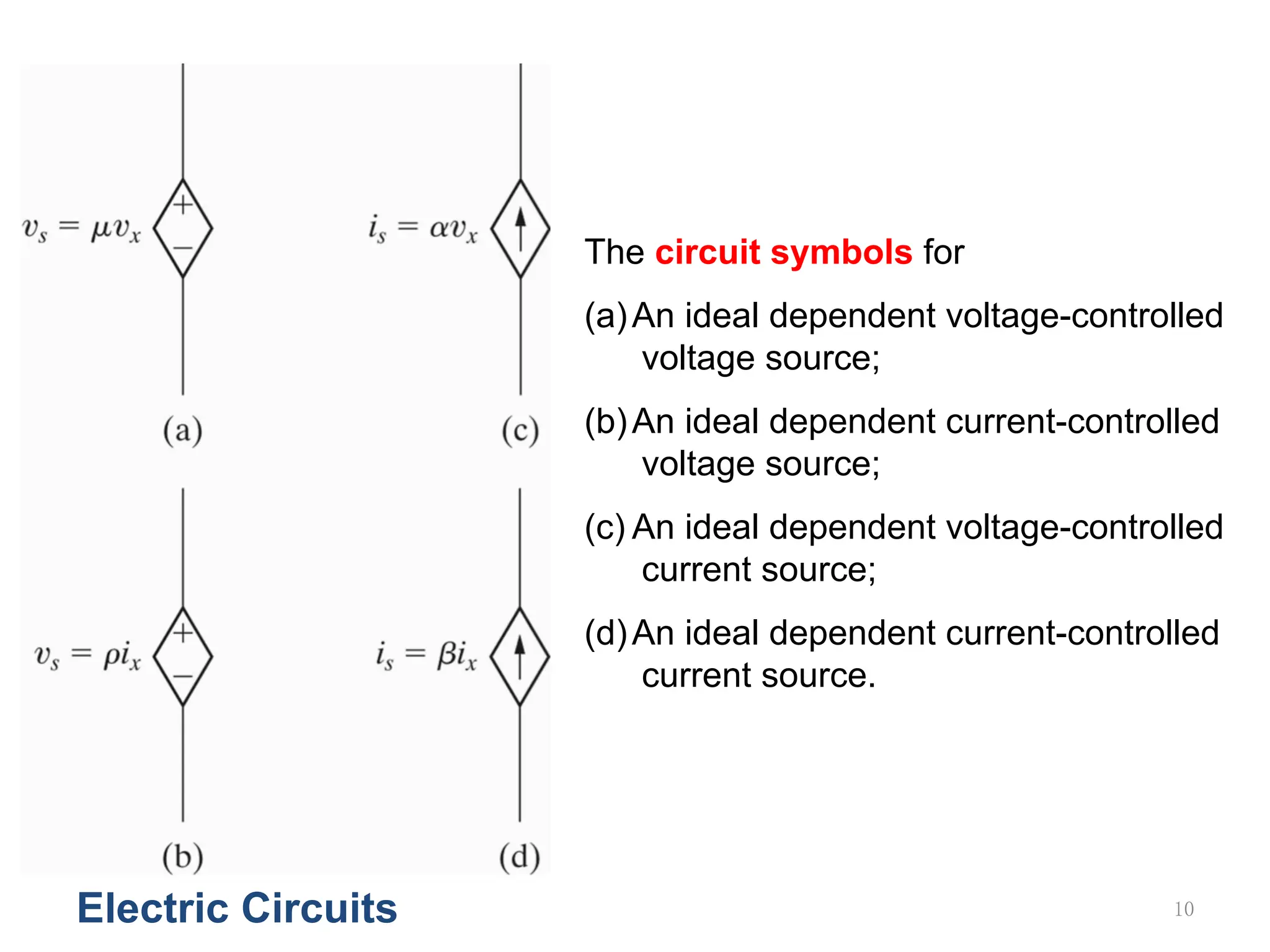
Thecircuit symbols for
(a)An ideal dependent voltage-controlled
voltage source;
(b)An ideal dependent current-controlled
voltage source;
(c) An ideal dependent voltage-controlled
current source;
(d)An ideal dependent current-controlled
current source.
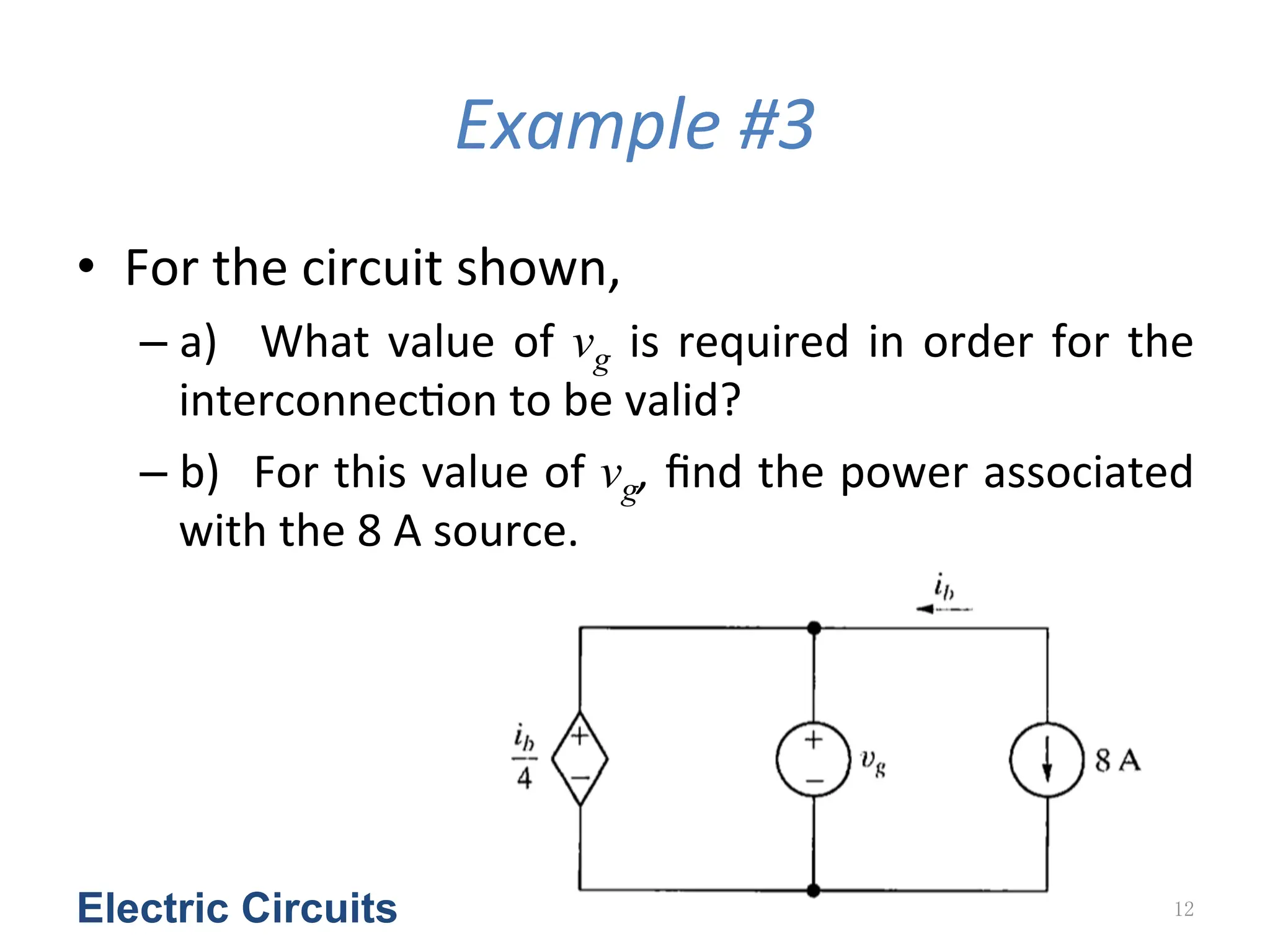
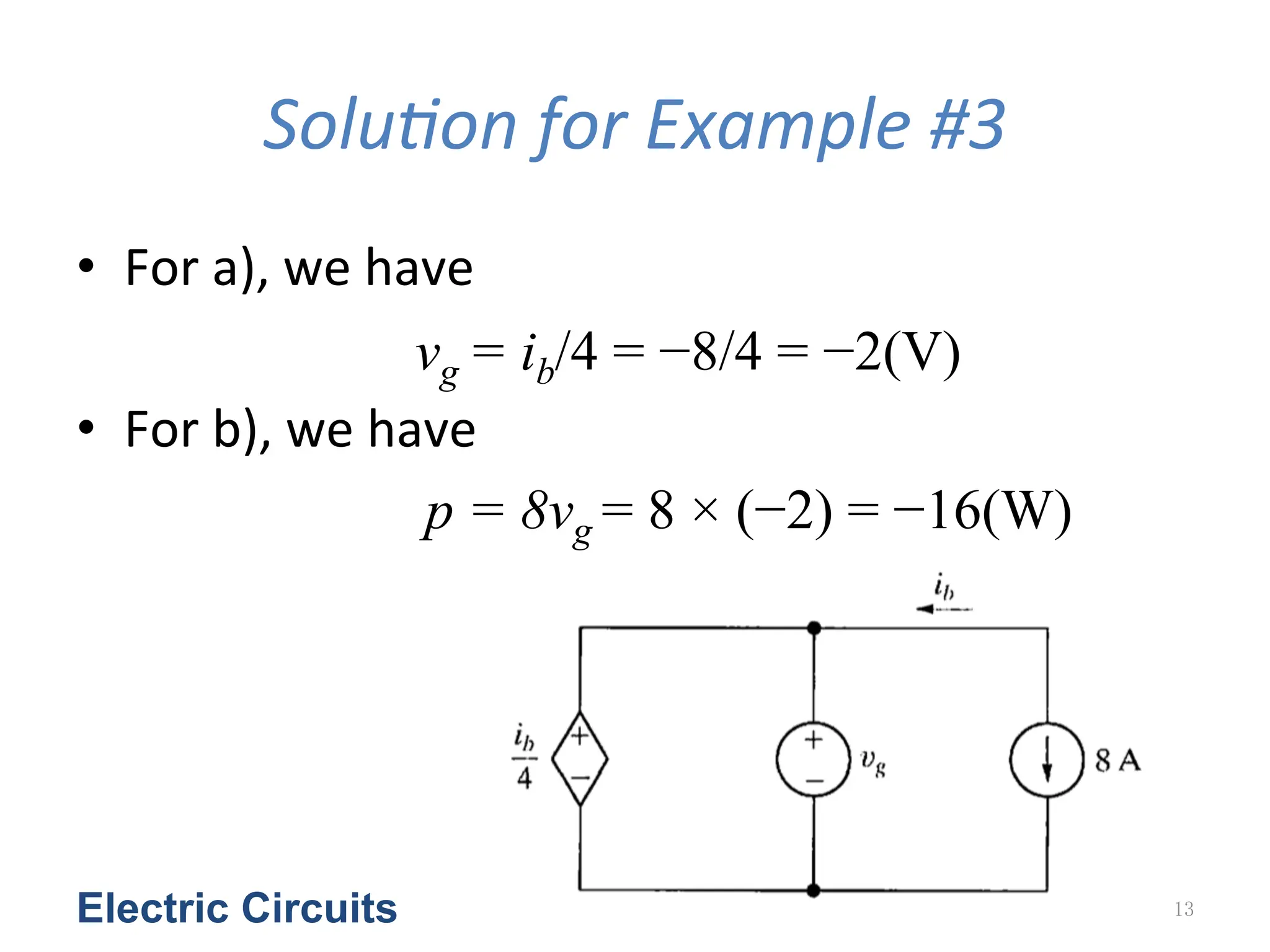
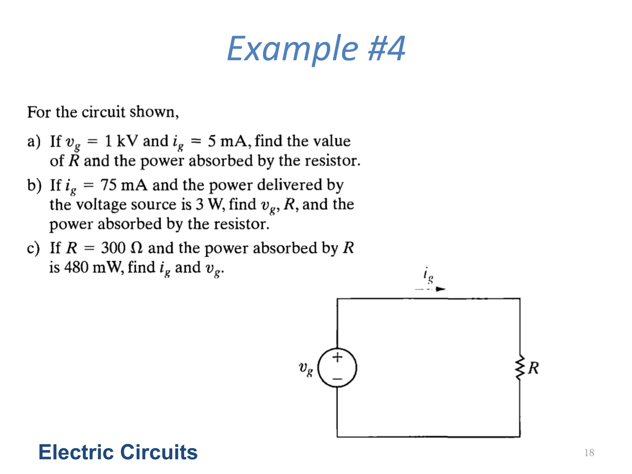
Example
#3
• For
the
circuit
shown,
– a)
What
value
of
vg is
required
in
order
for
the
interconnec<on
to
be
valid?
– b)
For
this
value
of
vg,
find
the
power
associated
with
the
8
A
source.
Electric Circuits 12
13.
SoluGon
for
Example
#3
• For
a),
we
have
• For
b),
we
have
Electric Circuits 13
vg = ib/4 = −8/4 = −2(V)
p = 8vg = 8 × (−2) = −16(W)
14.
Electrical
Resistance
(Ohm’s
Law)
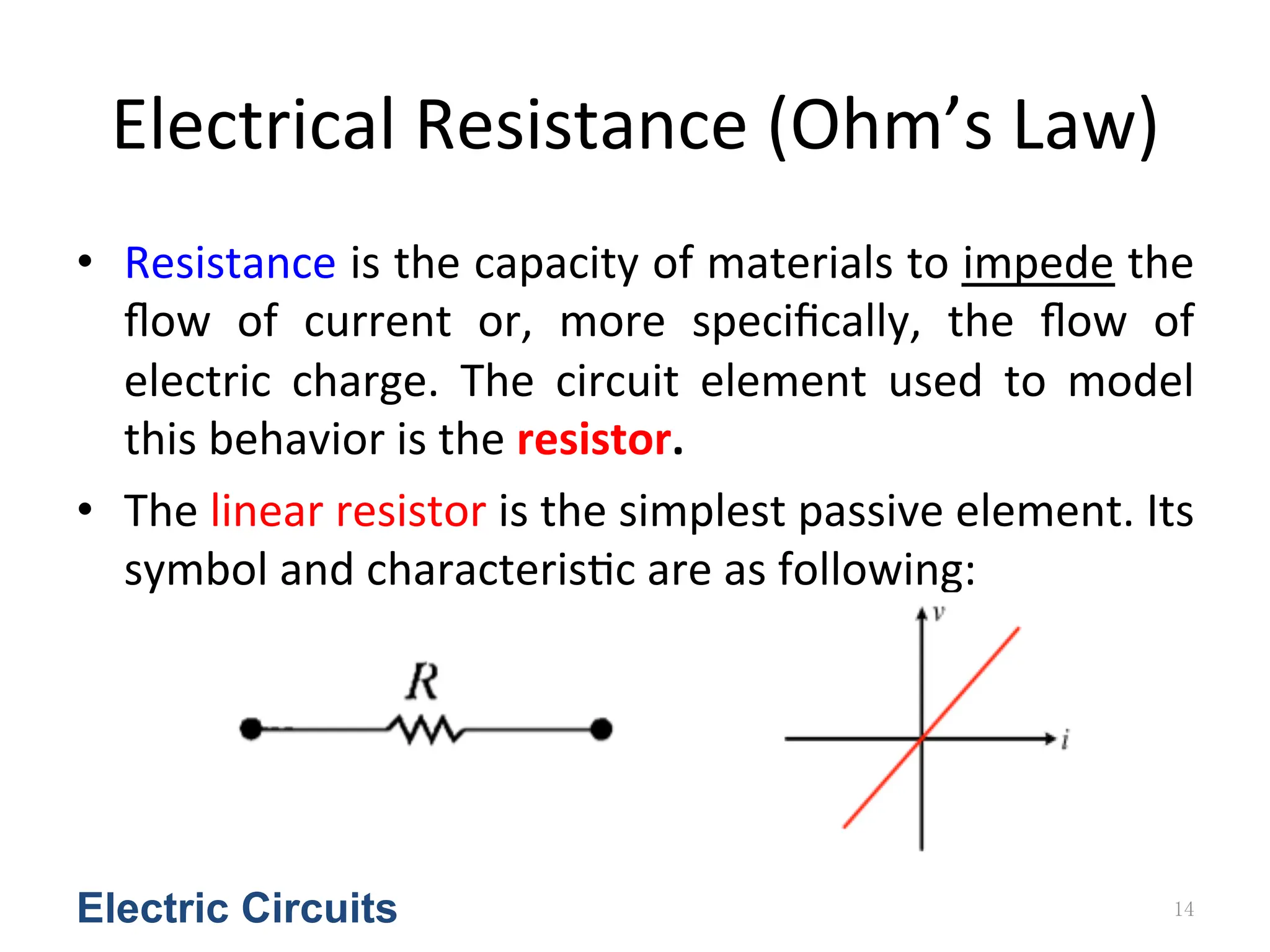
• Resistance
is
the
capacity
of
materials
to
impede
the
flow
of
current
or,
more
specifically,
the
flow
of
electric
charge.
The
circuit
element
used
to
model
this
behavior
is
the
resistor.
• The
linear
resistor
is
the
simplest
passive
element.
Its
symbol
and
characteris<c
are
as
following:
Electric Circuits 14
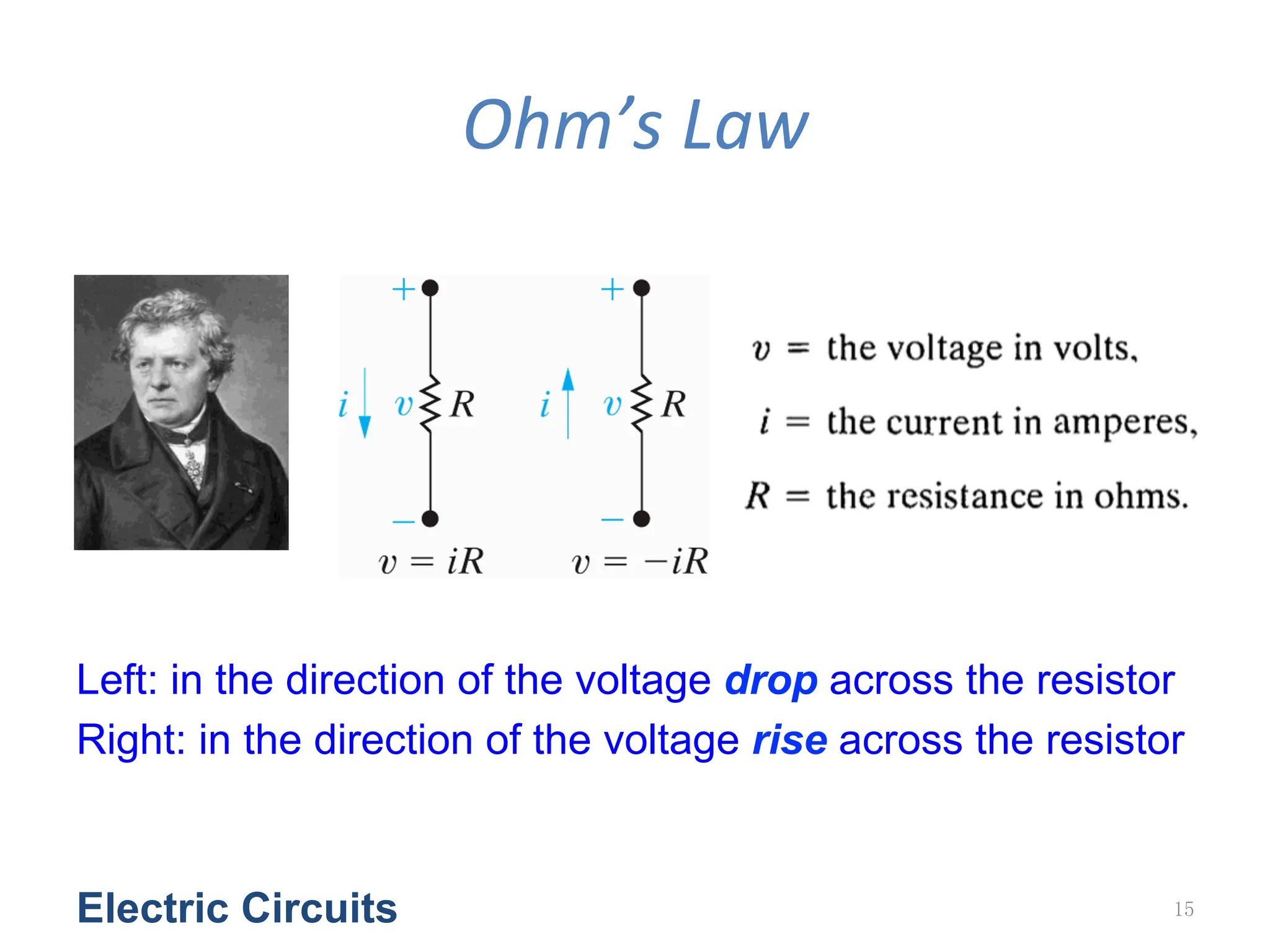
15.
Ohm’s
Law
Electric Circuits15
Left: in the direction of the voltage drop across the resistor
Right: in the direction of the voltage rise across the resistor
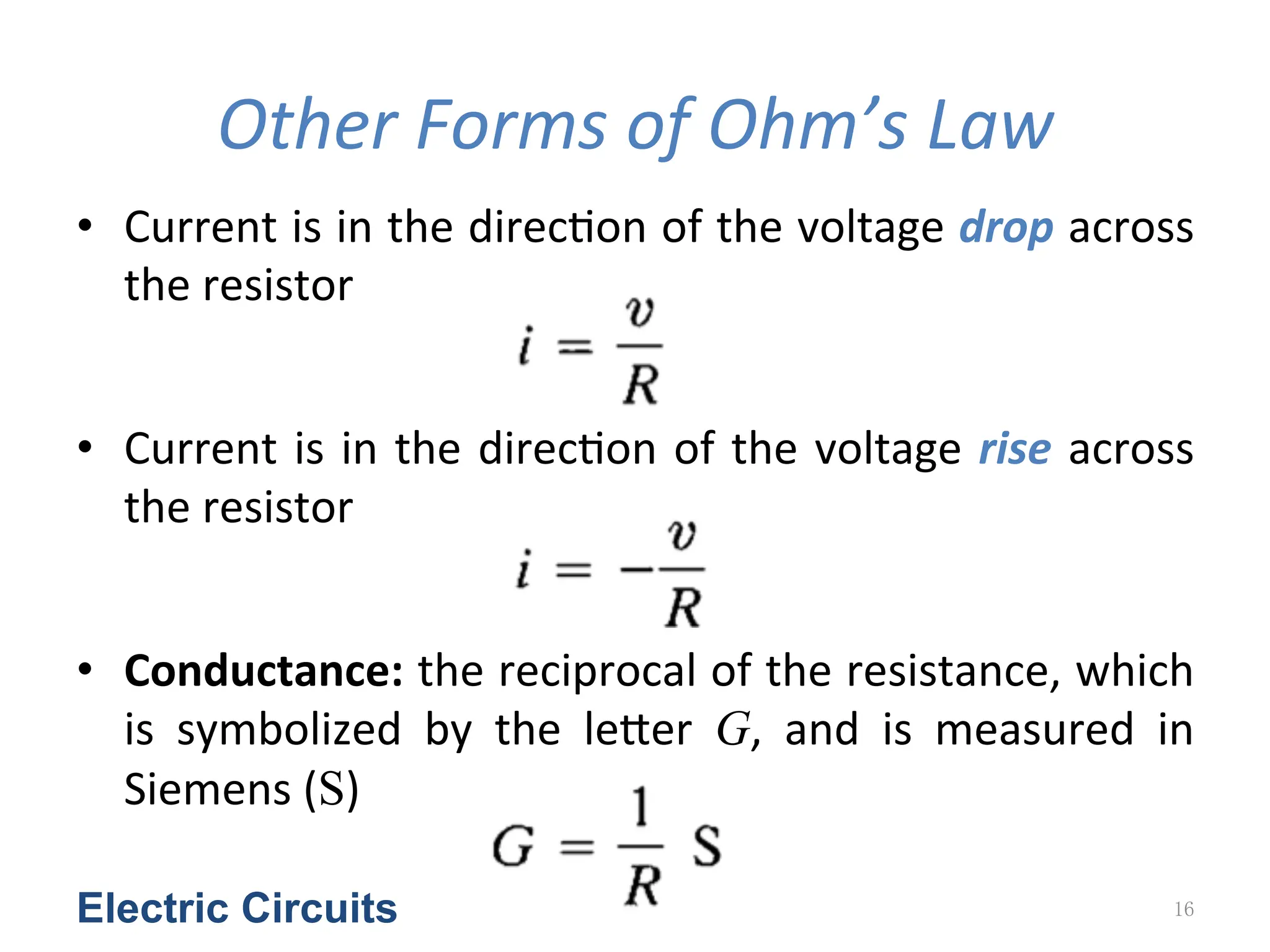
16.
Other
Forms
of
Ohm’s
Law
• Current
is
in
the
direc<on
of
the
voltage
drop
across
the
resistor
• Current
is
in
the
direc<on
of
the
voltage
rise
across
the
resistor
• Conductance:
the
reciprocal
of
the
resistance,
which
is
symbolized
by
the
leYer
G,
and
is
measured
in
Siemens
(S)
Electric Circuits 16
17.
Power
in
Different
Forms
Electric Circuits 17
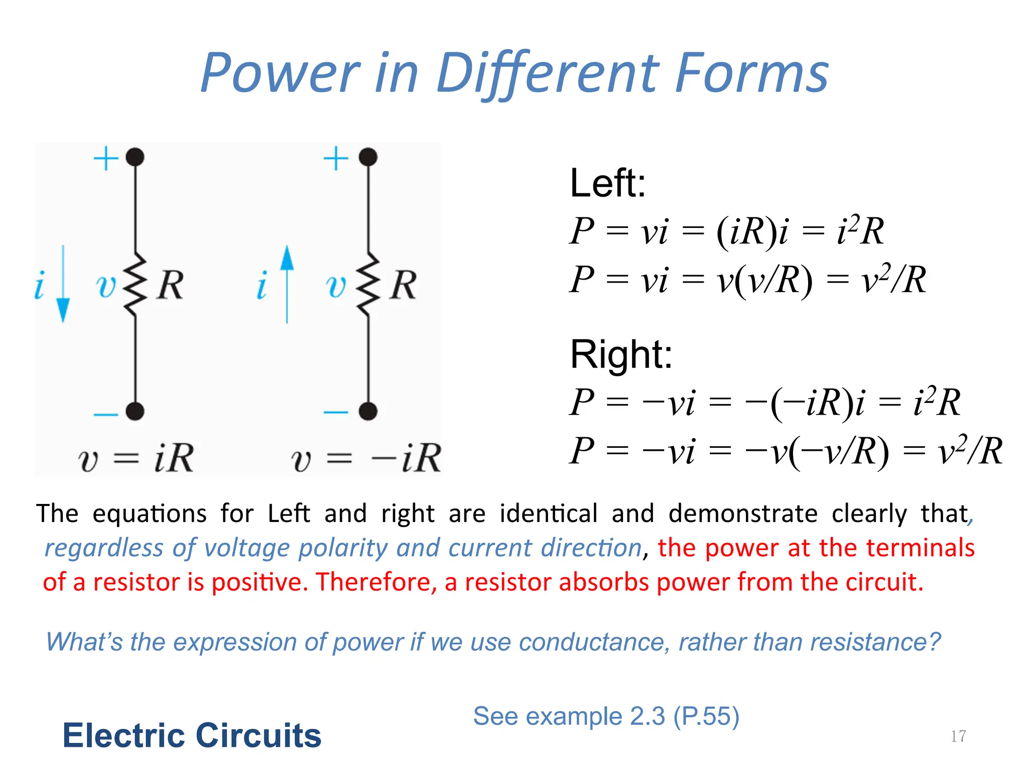
Left:
P = vi = (iR)i = i2R
P = vi = v(v/R) = v2/R
Right:
P = −vi = −(−iR)i = i2R
P = −vi = −v(−v/R) = v2/R
The
equa<ons
for
LeZ
and
right
are
iden<cal
and
demonstrate
clearly
that,
regardless
of
voltage
polarity
and
current
direcGon,
the
power
at
the
terminals
of
a
resistor
is
posi<ve.
Therefore,
a
resistor
absorbs
power
from
the
circuit.
What’s the expression of power if we use conductance, rather than resistance?
See example 2.3 (P.55)
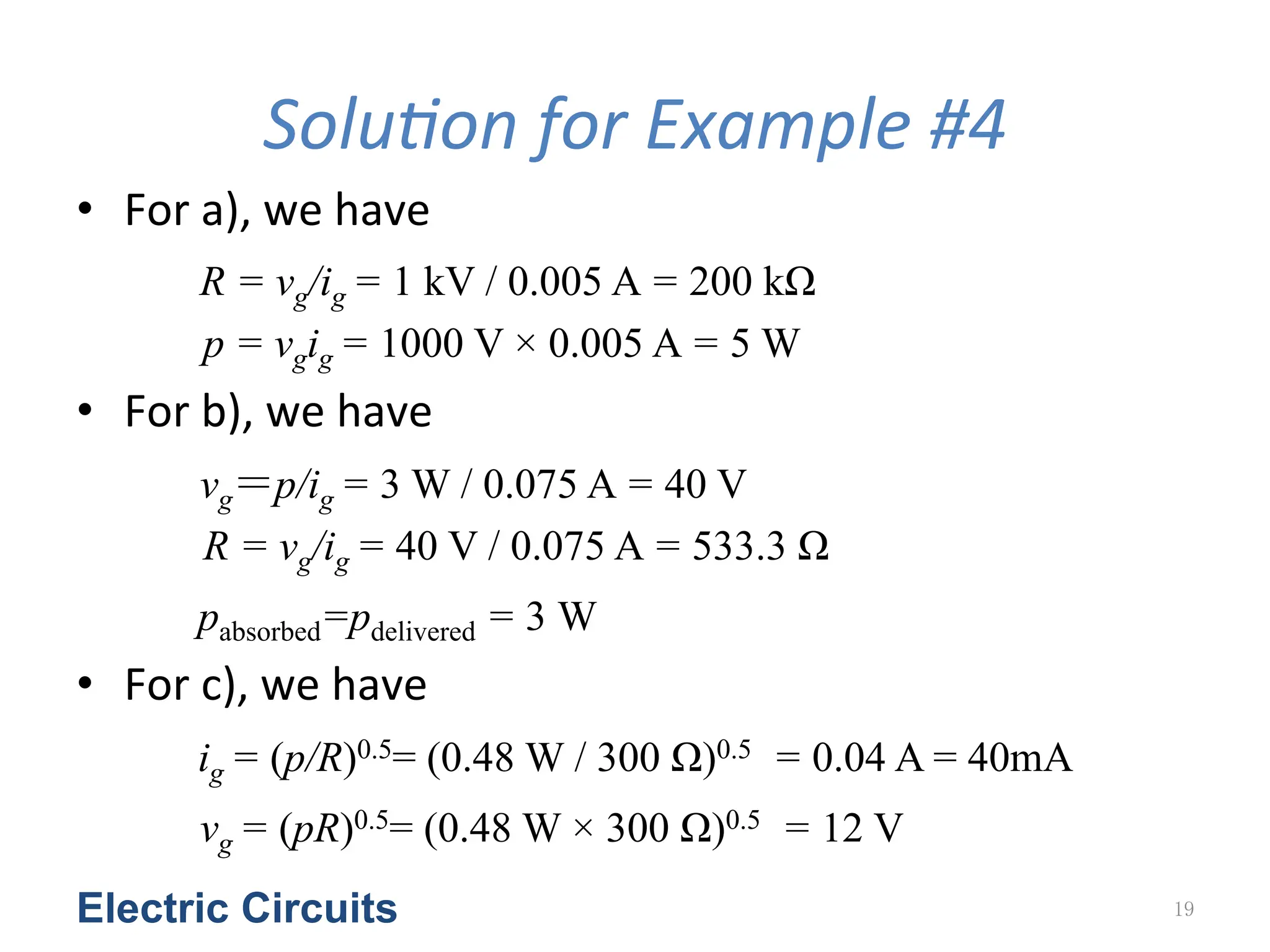
SoluGon
for
Example
#4
• For
a),
we
have
R = vg/ig = 1 kV / 0.005 A = 200 kΩ
p = vgig = 1000 V × 0.005 A = 5 W
• For
b),
we
have
vg=p/ig = 3 W / 0.075 A = 40 V
R = vg/ig = 40 V / 0.075 A = 533.3 Ω
pabsorbed=pdelivered = 3 W
• For
c),
we
have
ig = (p/R)0.5= (0.48 W / 300 Ω)0.5 = 0.04 A = 40mA
vg = (pR)0.5= (0.48 W × 300 Ω)0.5 = 12 V
Electric Circuits 19
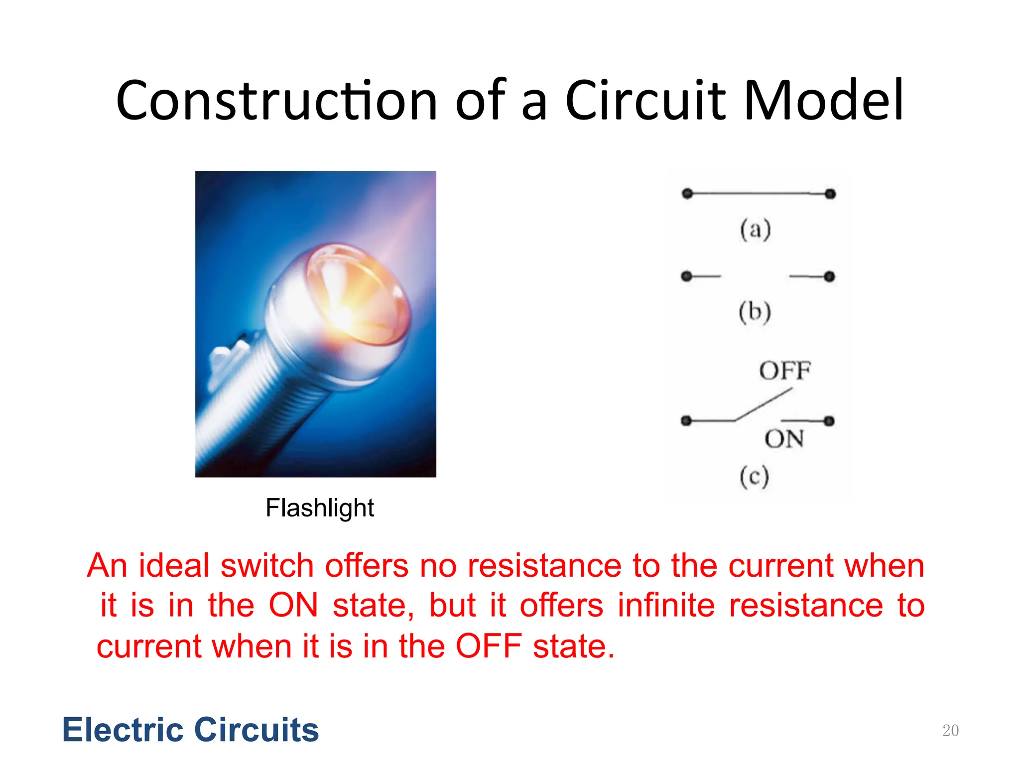
20.
Construc<on
of
a
Circuit
Model
Electric Circuits 20
Flashlight
An ideal switch offers no resistance to the current when
it is in the ON state, but it offers infinite resistance to
current when it is in the OFF state.
21.
Electric Circuits 21
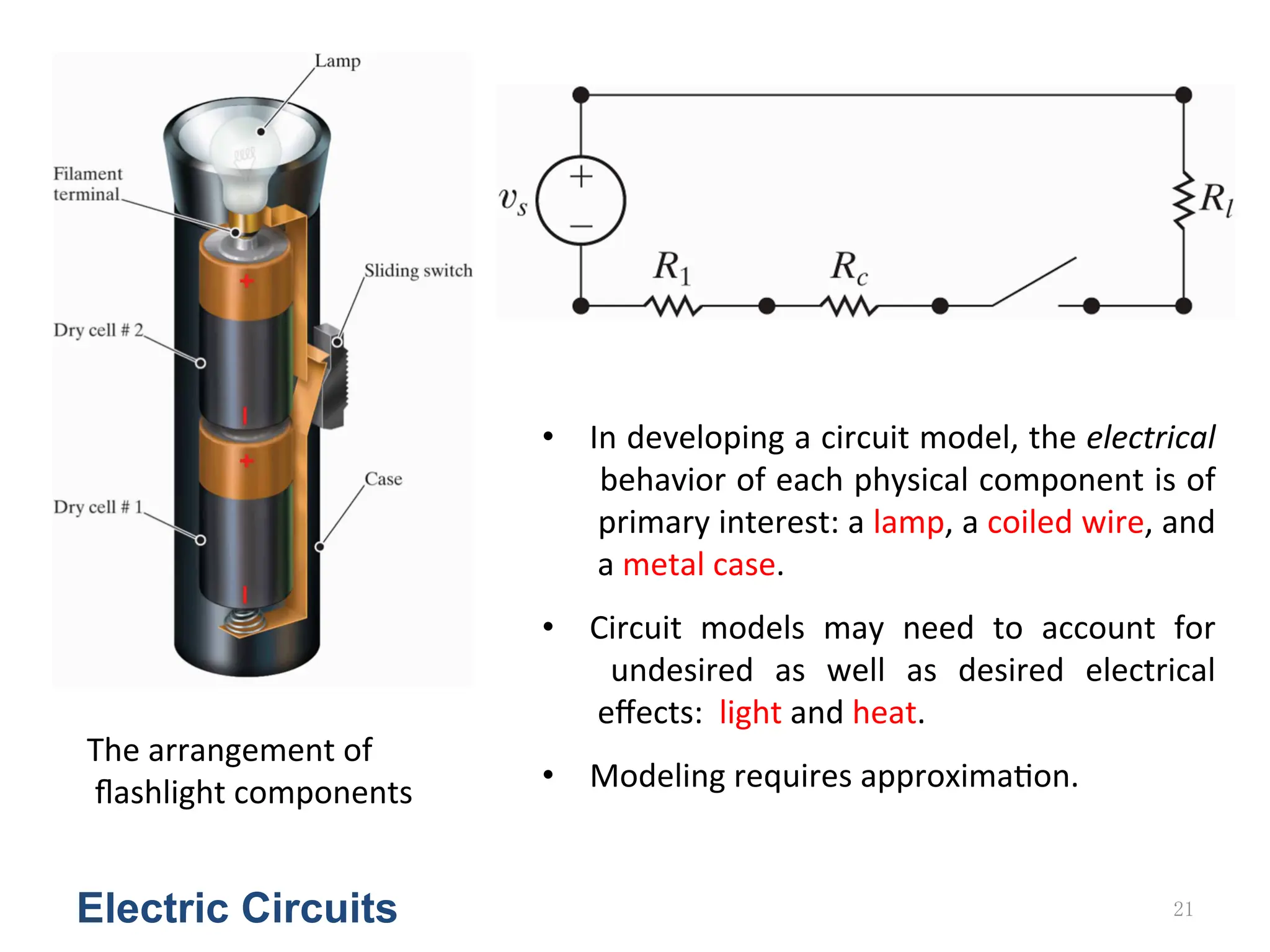
The
arrangement
of
flashlight
components
• In
developing
a
circuit
model,
the
electrical
behavior
of
each
physical
component
is
of
primary
interest:
a
lamp,
a
coiled
wire,
and
a
metal
case.
• Circuit
models
may
need
to
account
for
undesired
as
well
as
desired
electrical
effects:
light
and
heat.
• Modeling
requires
approxima<on.
22.
Example
#5
• The
voltage
and
current
are
measured
at
the
terminals
of
the
device
illustrated
in
(a),
and
the
values
of
vt
and
it
are
tabulated
in
(b).
Construct
a
circuit
model
of
the
device
inside
the
box.
Electric Circuits 22
23.
SoluGon
for
Example
#5
Electric Circuits 23
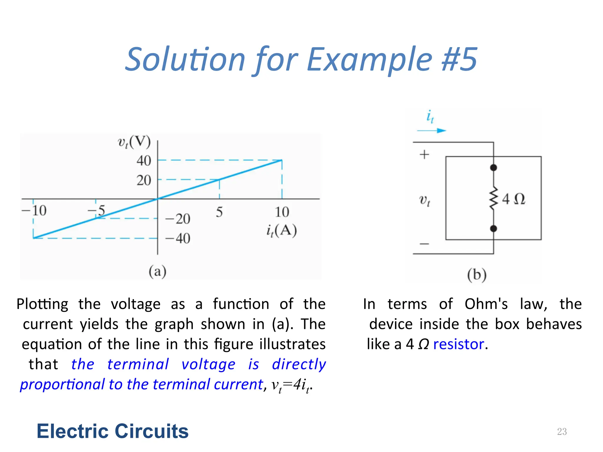
Plong
the
voltage
as
a
func<on
of
the
current
yields
the
graph
shown
in
(a).
The
equa<on
of
the
line
in
this
figure
illustrates
that
the
terminal
voltage
is
directly
proporGonal
to
the
terminal
current,
vt=4it.
In
terms
of
Ohm's
law,
the
device
inside
the
box
behaves
like
a
4
Ω
resistor.
24.
Kirchhoff’s
Law
Electric Circuits24
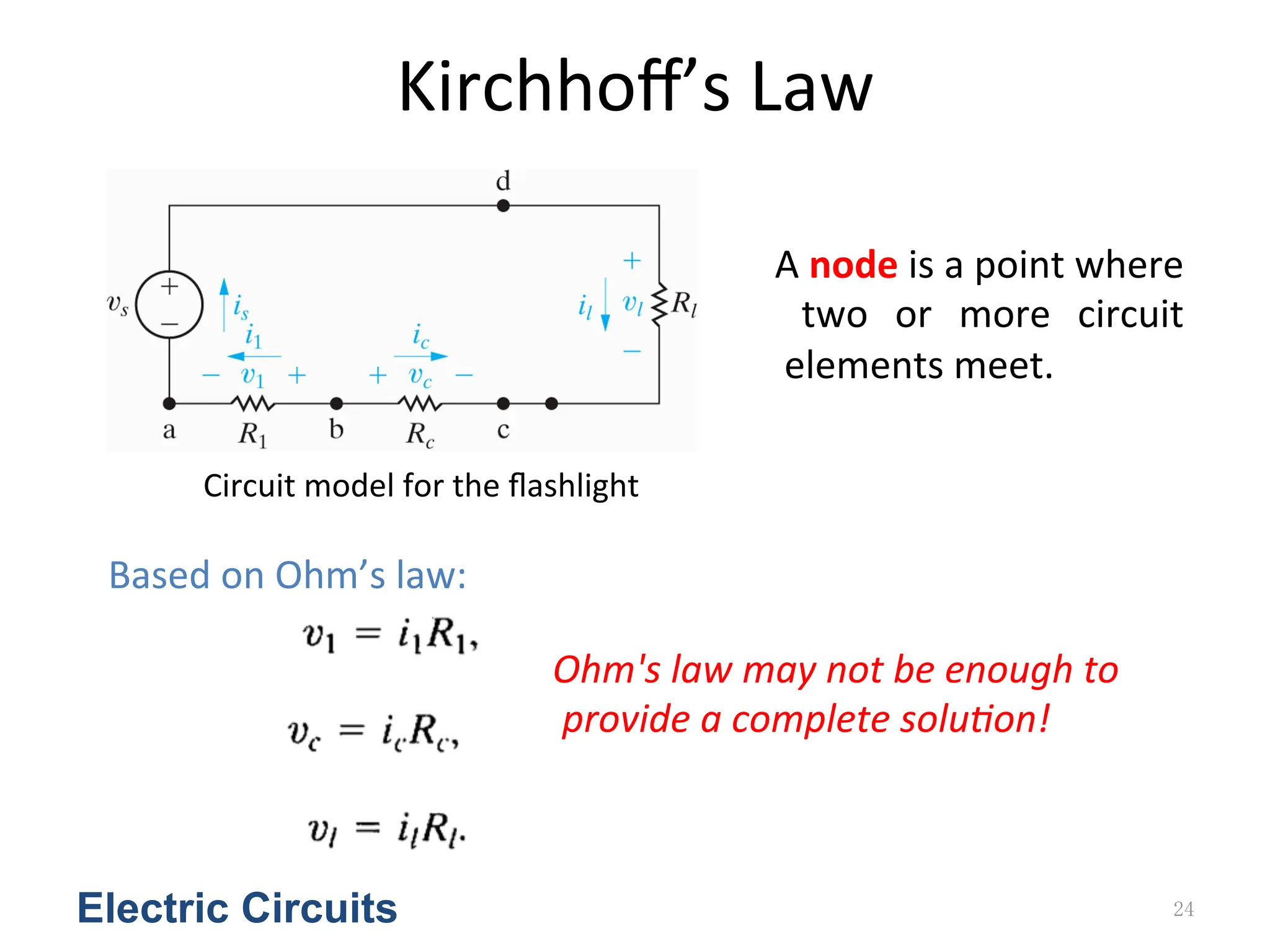
A
node
is
a
point
where
two
or
more
circuit
elements
meet.
Ohm's
law
may
not
be
enough
to
provide
a
complete
soluGon!
Based
on
Ohm’s
law:
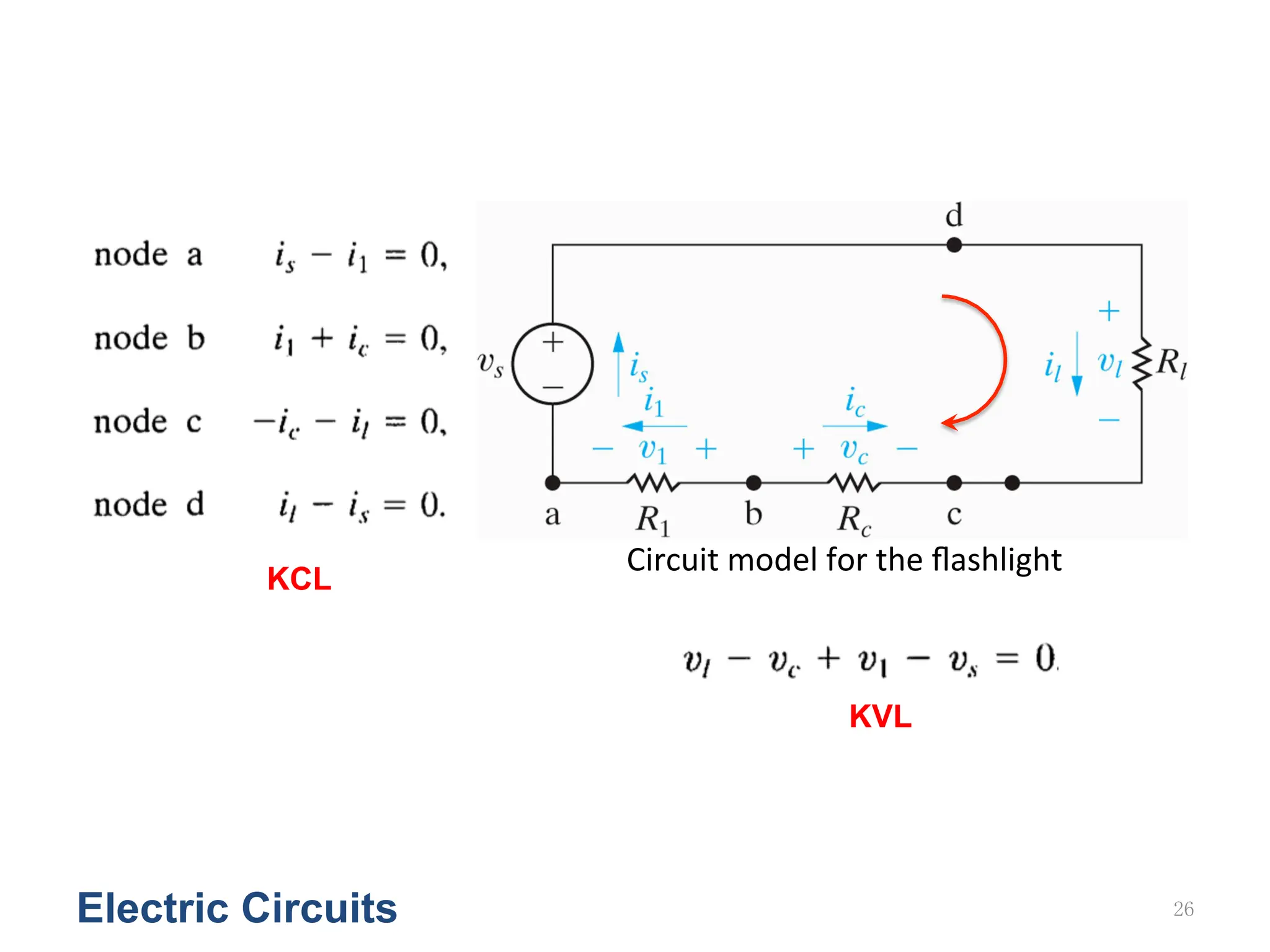
Circuit
model
for
the
flashlight
25.
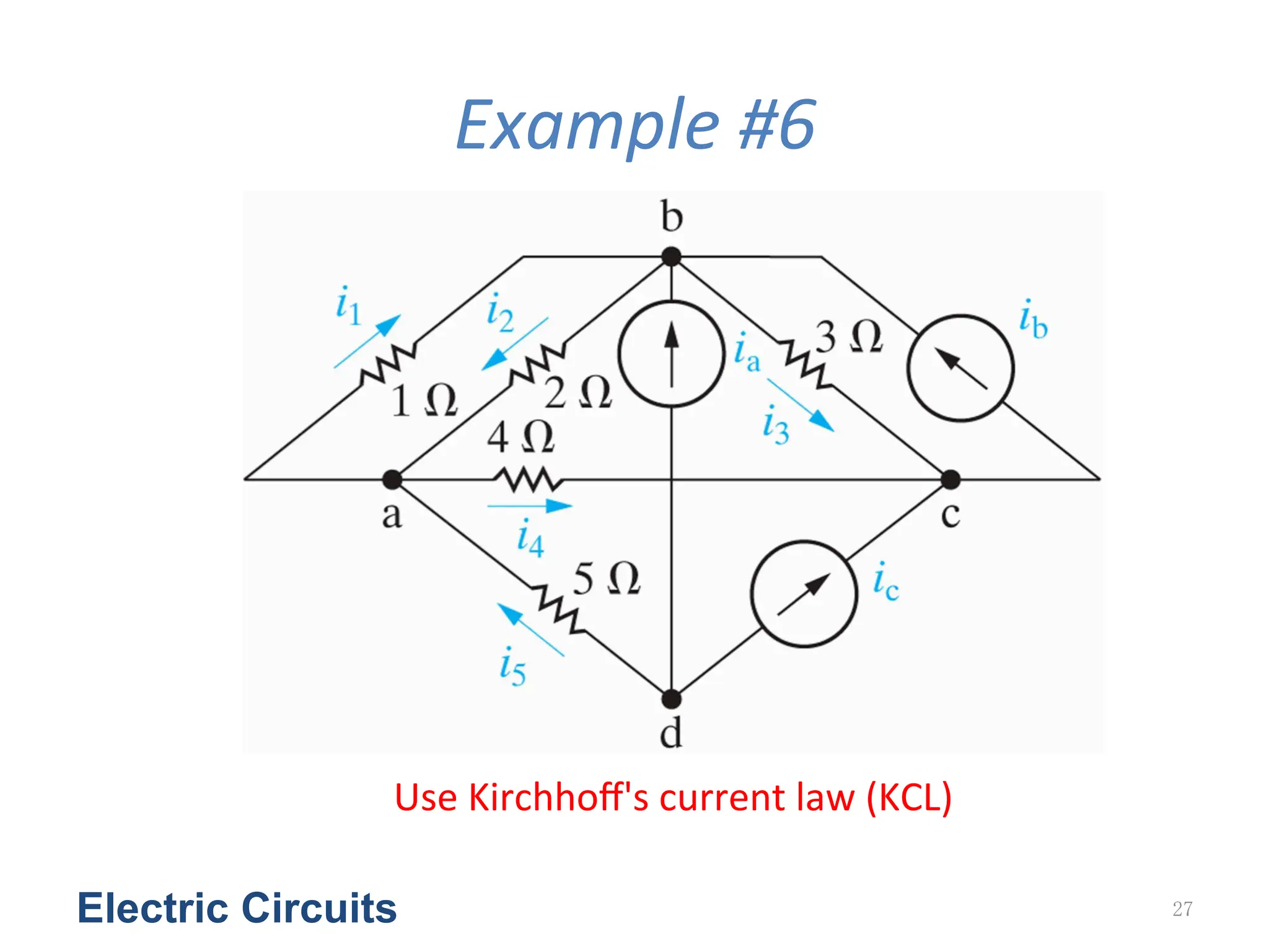
• Kirchhoff's
current
law
(KCL):
The
algebraic
sum
of
all
the
currents
at
any
node
in
a
circuit
equals
zero.
• Kirchhoffs
voltage
law
(KVL):
The
algebraic
sum
of
all
the
voltages
around
any
closed
path
in
a
circuit
equals
zero.
Electric Circuits 25
Reference
direc&on
is
important!
KCL:
Assign
a
posi<ve
sign
to
a
current
leaving
a
node
requires
assigning
a
nega<ve
sign
to
a
current
entering
a
node,
or
vice
versa.
KVL:
As
we
trace
a
closed
path,
assign
a
posi<ve
sign
to
a
voltage
rise
requires
assigning
a
nega<ve
sign
to
a
voltage
drop,
or
vice
versa.
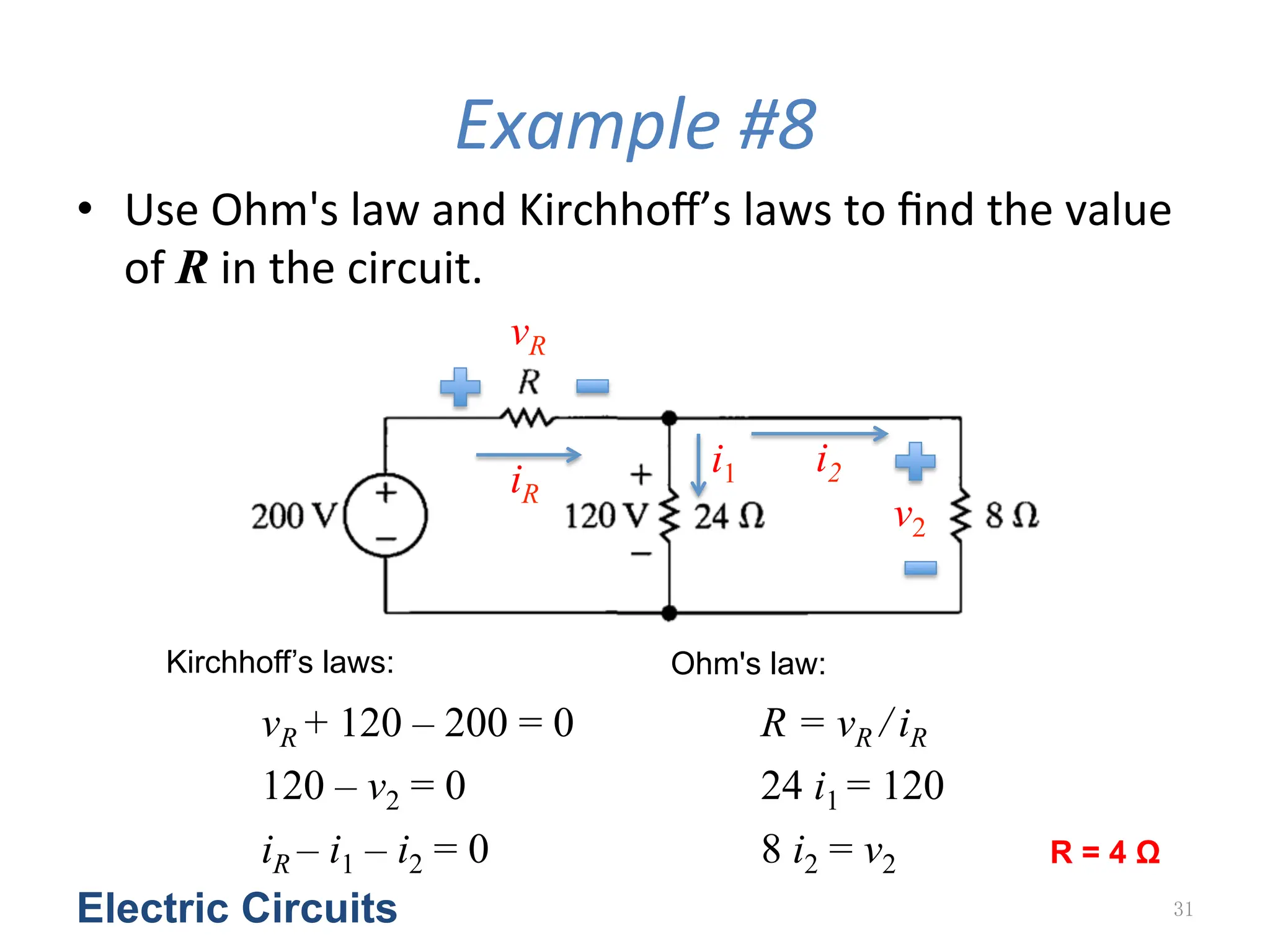
Example
#8
• Use
Ohm's
law
and
Kirchhoff’s
laws
to
find
the
value
of
R
in
the
circuit.
Electric Circuits 31
vR
iR
i1 i2
vR + 120 – 200 = 0
iR – i1 – i2 = 0
v2
120 – v2 = 0
R = vR / iR
8 i2 = v2
24 i1 = 120
Kirchhoff’s laws: Ohm's law:
R = 4 Ω
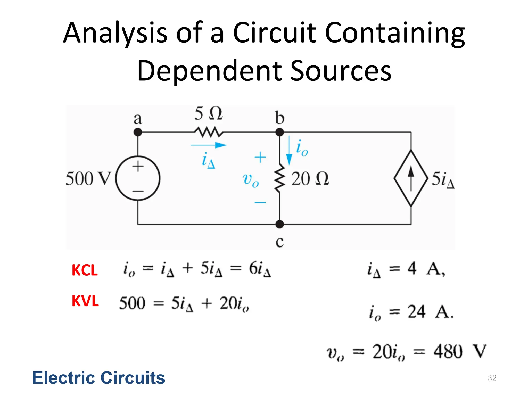
32.
Analysis
of
a
Circuit
Containing
Dependent
Sources
Electric Circuits 32
KCL
KVL
33.
Example
#9
a)
Use
Kirchhoffs
laws
and
Ohm's
law
to
find
the
voltage
vo as
shown
in
the
Figure.
b)
Show
that
your
solu<on
is
consistent
with
the
constraint
that
the
total
power
developed
in
the
circuit
equals
the
total
power
dissipated.
Electric Circuits 33
34.
SoluGon
for
Example
#9
Electric Circuits 34
By
using
Kirchhoff’s
voltage
law
(KVL),
we
have
Then,
by
using
Ohm’s
law,
we
have
Please
check
the
power
balancing!