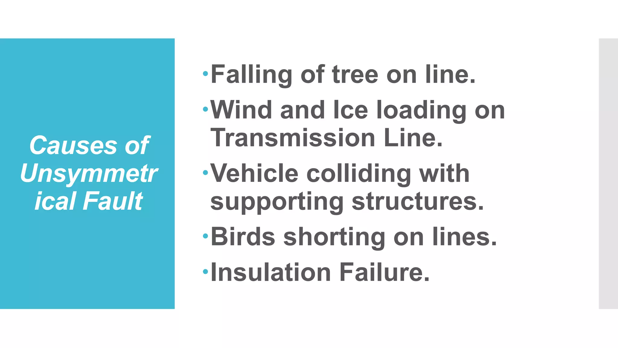
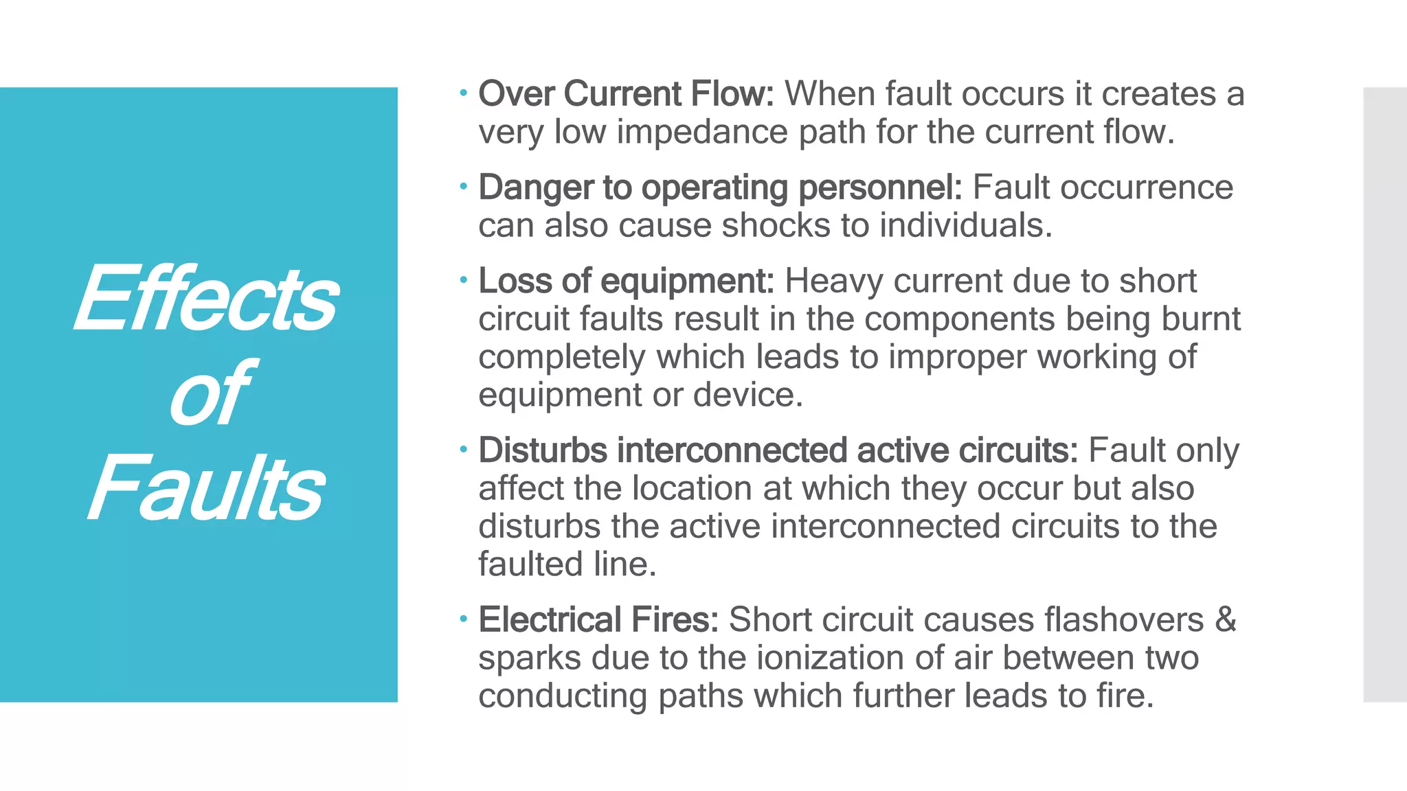
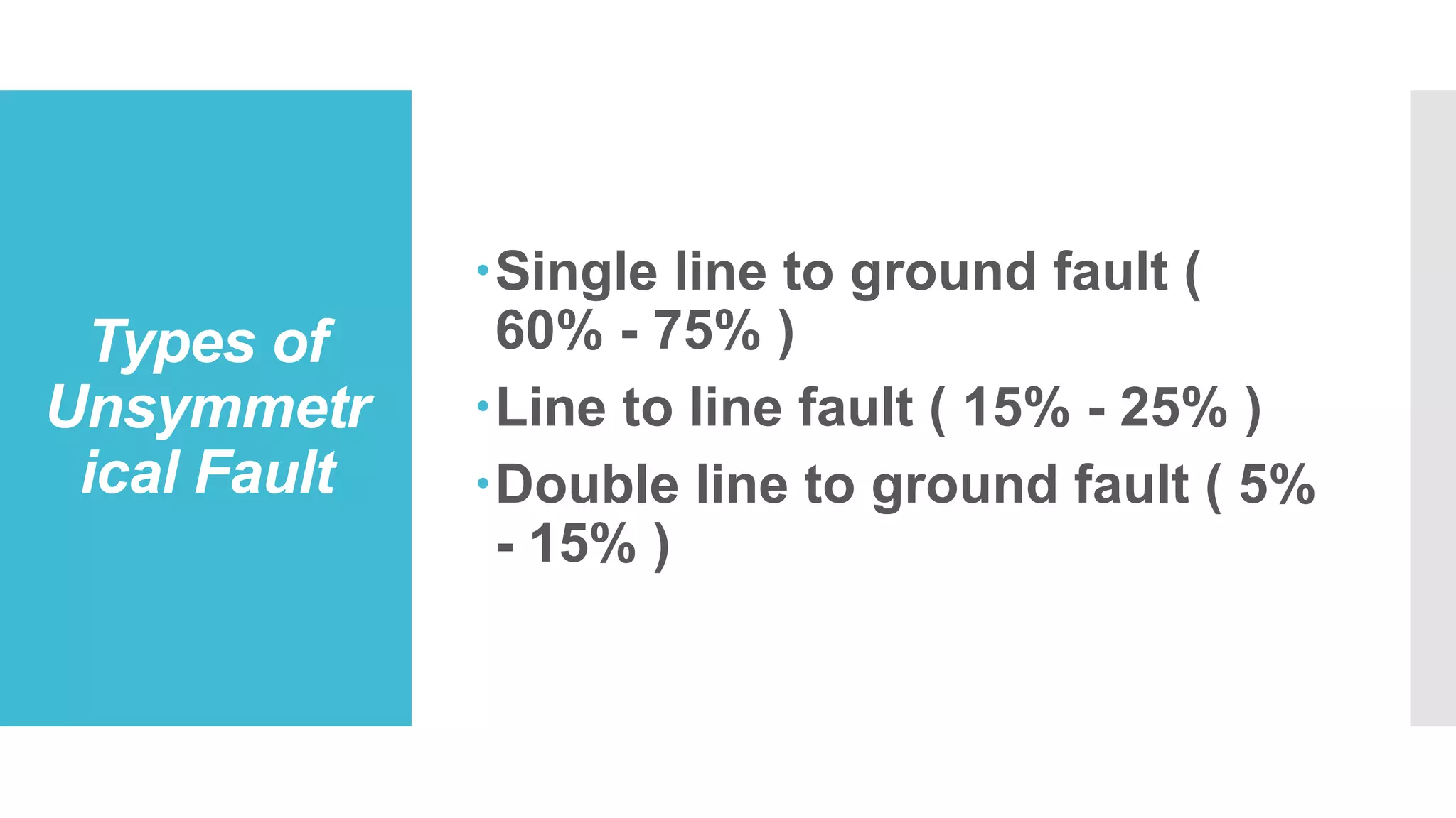
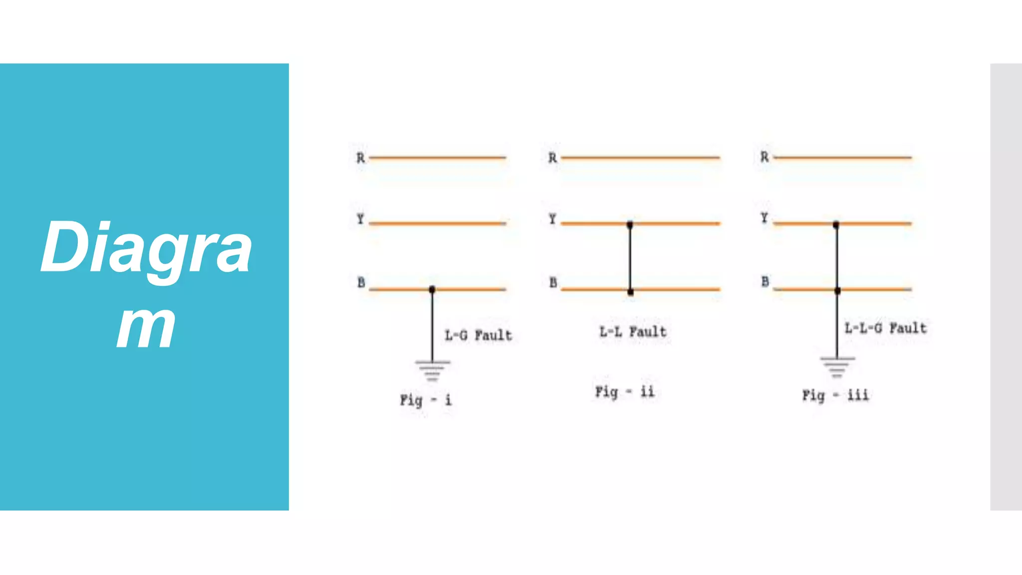
This document discusses unsymmetrical faults in power systems. It begins by defining unsymmetrical faults as faults that result in unequal line currents and displacement. It then discusses the causes of unsymmetrical faults such as falling trees, wind, and insulation failures. The document also summarizes the effects of faults such as overcurrent, equipment loss, and electrical fires. It describes the types of unsymmetrical faults and introduces symmetrical components and Fortescue's Theorem for analyzing unsymmetrical faults using positive, negative, and zero sequence networks. Finally, it briefly discusses fault limiting devices like fuses, circuit breakers, and protective relays.
Electrical fault is the deviation of voltages and currents from nominal values or states. Under normal operating conditions, power system equipment or lines carry normal voltages and currents which results in a safer operation of the system.
Unit I: Introduction to Protection System:
Introduction to protection system and its elements, functions of protective relaying, protective zones, primary and backup protection, desirable qualities of protective relaying, basic terminology.
Relays:
Electromagnetic, attracted and induction type relays, thermal relay, gas actuated relay, design considerations of electromagnetic relay.
Unit-II: Relay Application and Characteristics:
Amplitude and phase comparators, over current relays, directional relays, distance relays, differential relay.
Static Relays: Comparison with electromagnetic relay, classification and their description, over current relays, directional relay, distance relays, differential relay.
Unit-III Protection of Transmission Line:
Over current protection, distance protection, pilot wire protection, carrier current protection, protection of bus, auto re-closing,
Unit-IV: Circuit Breaking:
Properties of arc, arc extinction theories, re-striking voltage transient, current chopping, resistance switching, capacitive current interruption, short line interruption, circuit breaker ratings.
Testing Of Circuit Breaker: Classification, testing station and equipments, testing procedure, direct and indirect testing.
Unit-V Apparatus Protection:
Protection of Transformer, generator and motor.
Circuit Breaker: Operating modes, selection of circuit breakers, constructional features and operation of Bulk Oil, Minimum Oil, Air Blast, SF6, Vacuum and d. c. circuit breakers.
Power System Analysis was a core subject for Electrical & Electronics Engineering, Based On Anna University Syllabus. The Whole Subject was there in this document.
Share with it ur friends & Follow me for more updates.!
SWICTH GEAR AND PROTECTION (2170906)
DISTANCE RELAY
• There are mainly Three types of distance relay
1) Impedance Relay
2) Reactance Relay
3) Mho Relay
POWER HARMONICS- SOURCES, ISSUES AND MITIGATIONASHIKS842
Various developments in the field of power system are being carried out to find a fruitful solution to mitigate the harmonics. some of the basic solutions are being described here.
SEMINAR PRESENTED ON 21 JANUARY 2017 CONDUCTED BY KERALA STATE ELECTRICITY BOARD ENGINEER'S ASSOCIATION.
Generator and Transformer Protection (PART 1)Dr. Rohit Babu
Part 1. Generator Protection
Protection of generators against stator faults
Rotor faults and abnormal conditions
Restricted earth fault and inter-turn fault protection
Numerical examples
In this presentation, we’ll describe types of fault in power system including :
Definition of Fault in Power System
Types of Fault and
A short description of various types of Fault
High Voltage Direct Current technology has certain characteristics which
make it especially attractive for transmission system applications. HVDC
transmission system is useful for long-distance transmission, bulk power delivery and
long submarine cable crossings and asynchronous interconnections. The study of
faults is essential for reasonable protection design because the faults will induce a
significant influence on operation of HVDC transmission system. This paper provides
the most dominant and frequent faults on the HVDC systems such as DC Line-to-
Ground fault and Line-to-Line fault on DC link and some common types of AC faults
occurs in overhead transmission system such as Line-to-Ground fault, Line-to-Line
fault and L-L-L fault. In HVDC system, faults on rectifier side or inverter side have
major affects on system stability. The various types of faults are considered in the
HVDC system which causes due to malfunctions of valves and controllers, misfire
and short circuit across the inverter station, flashover and three phase short circuit.
The various faults occurs at the converter station of a HVDC system and
Controlling action for those faults. Most of the studies have been conducted on line
faults. But faults on rectifier or inverter side of a HVDC system have great impact on
system stability. Faults considered are fire-through, misfire, and short circuit across
the inverter station, flashover, and a three-phase short circuit in the ac system. These
investigations are studied using matlab simulink models and the result represented in
the form of typical time responses.
Protection of transmission lines (distance)Rohini Haridas
This gives idea about necessity of protection of transmission line and protection based on time grading as well as on current grading. Also includes three step distance protection of transmission line
Transmission line short circuit analysis by impedance matrix method IJECEIAES
Fault analysis is the process of determining the magnitude of fault voltage and current during the occurrence of different types of fault in electrical power system. Transmission line fault analysis is usually done for both symmetrical and unsymmetrical faults. Symmetrical faults are called three-phase balance fault while unsymmetrical faults include: single line-to-ground, line-to-line, and double line-to-ground faults. In this research, bus impedance matrix method for fault analysis is presented. Bus impedance matrix approach has several advantages over Thevenin’s equivalent method and other conventional approaches. This is because the off-diagonal elements represent the transfer impedance of the power system network and helps in calculating the branch fault currents during a fault. Analytical and simulation approaches on a single line-to-ground fault on 3-bus power system network under bolted fault condition were used for the study. Both methods were compared and result showed negligible deviation of 0.02% on the average. The fault currents under bolted condition for the single line-to-ground fault were found to be 4. 7244p.u while the bus voltage is 0. 4095p.u for buses 1 and 2 respectively and 0. 00p.u for bus 3 since the fault occurred at this bus. Therefore, there is no need of burdensomely connecting the entire three sequence network during fault analysis in electrical power system.
Harmonics are sinusoidal voltages or currents having frequencies that are whole multiples of the frequency at which the supply system is designed to operate (e.g. 50Hz or 60 Hz).Harmonics are simply a technique to analyze the current drawn by computers, electronic ballasts, variable frequency drives and other equipment which have modem “transformer-less” power supplies.
Matlab Simulink in Three-Phase Fault Analysis on Transmission linepamu17
When different types of fault occurs in power system then in the process of transmission line fault analysis, determination of bus
voltage and the rms line current are possible. While consulting with the power system the terms bus voltage and rms current of line are very important. In case of three phase power system mainly two faults occurs, three phase balance fault and unbalance fault on transmission line of power system, such as line to ground fault, double line to ground fault and double line fault. The transmission line fault analysis helps to select and develop a better for protection purpose[1]. For the protection of transmission line we place the circuit breakers and its rating is depends on triple line fault. The reason behind is that the triple line fault current is very high as compare to other fault current.
simulation in computer, the analysis of transmission line fault can be easily carried out. The main purpose of this paper is to study the general fault type which is Unbalance faults of transmission line in the power system. Also to perform the analysis and obtain the Result of various parameters (voltage, current, power etc.) from simulation on those types of fault Using MATLAB. A new
modeling framework for analysis and simulation of unbalance fault
in power system on IEEE 14 bus system is Procedure includes the frequency information in dynamical models and produces approximate nonlinear Models that are well adopted for analysis and simulation. The transformer model includes Saturation. The parameters have been obtained from practical or experimental measurement.
Conclusion:-
The aforementioned benefits are typically seen to increase transmission lines capacity. Benefits of TCSC are not subject only to newly built TCSC installation but they can also be achieved by upgrading existing series compensation on the thyristors controlled series compensation or only its part, thus considerably extended its influence and usefulness.
An optical fiber or optical fibre is a flexible, transparent fiber made by drawing glass (silica) or plastic to a diameter slightly thicker than that of a human hair. Optical fibers are used most often as a means to transmit light between the two ends of the fiber and find wide usage in fiber-optic communications, where they permit transmission over longer distances and at higher bandwidths (data rates) than wire cables. Fibers are used instead of metal wires because signals travel along them with less loss; in addition, fibers are immune to electromagnetic interference, a problem from which metal wires suffer excessively. Fibers are also used for illumination and imaging, and are often wrapped in bundles so that they may be used to carry light into, or images out of confined spaces, as in the case of a fiberscope. Specially designed fibers are also used for a variety of other applications, some of them being fiber optic sensors and fiber lasers.
An alternator is an electrical generator that converts mechanical energy to electrical energy in the form of alternating current. For reasons of cost and simplicity, most alternators use a rotating magnetic field with a stationary armature. Occasionally, a linear alternator or a rotating armature with a stationary magnetic field is used. In principle, any AC electrical generator can be called an alternator, but usually the term refers to small rotating machines driven by automotive and other internal combustion engines. An alternator that uses a permanent magnet for its magnetic field is called a magneto. Alternators in power stations driven by steam turbines are called turbo-alternators. Large 50 or 60 Hz three phase alternators in power plants generate most of the world's electric power, which is distributed by electric power grids.
Wireless power transfer (WPT), wireless power transmission, wireless energy transmission, or electromagnetic power transfer is the transmission of electrical energy without wires. Wireless power transmission technologies use time-varying electric, magnetic, or electromagnetic fields. Wireless transmission is useful to power electrical devices where interconnecting wires are inconvenient, hazardous, or are not possible.
In signal processing, a digital filter is a system that performs mathematical operations on a sampled, discrete-time signal to reduce or enhance certain aspects of that signal. This is in contrast to the other major type of electronic filter, the analog filter, which is an electronic circuit operating on continuous-time analog signals.
Ward Leonard Control, also known as the Ward Leonard Drive System, was a widely used DC motor speed control system introduced by Harry Ward Leonard in 1891. In early 1900s, the control system of Ward Leonard was adopted by the U.S. Navy and also used in passenger lift of large mines.
A microprocessor is a type of integrated circuit or chip and is the heart of every computer. Ever since the 1980s, advertisements for personal computers have made a big deal about the microprocessors inside the box, even though every computer relies on dozens of other integrated circuits to work properly. But when it was first invented, engineers thought that the microprocessor would be an entire computer on a chip.
An embedded system is a computer system with a dedicated function within a larger mechanical or electrical system, often with real-time computing constraints. It is embedded as part of a complete device often including hardware and mechanical parts. Embedded systems control many devices in common use today. Ninety-eight percent of all microprocessors are manufactured as components of embedded systems.
In electric power generation a combined cycle is an assembly of heat engines that work in tandem from the same source of heat, converting it into mechanical energy, which in turn usually drives electrical generators. The principle is that after completing its cycle (in the first engine), the temperature of the working fluid engine is still high enough that a second subsequent heat engine may extract energy from the waste heat that the first engine produced. By combining these multiple streams of work upon a single mechanical shaft turning an electric generator, the overall net efficiency of the system may be increased by 50–60%. That is, from an overall efficiency of say 34% (in a single cycle) to possibly an overall efficiency of 51% (in a mechanical combination of two cycles) in net Carnot thermodynamic efficiency. This can be done because heat engines are only able to use a portion of the energy their fuel generates (usually less than 50%). In an ordinary (non combined cycle) heat engine the remaining heat (e.g., hot exhaust fumes) from combustion is generally wasted.
Combining two or more thermodynamic cycles results in improved overall efficiency, reducing fuel costs. In stationary power plants, a widely used combination is a gas turbine (operating by the Brayton cycle) burning natural gas or synthesis gas from coal, whose hot exhaust powers a steam power plant (operating by the Rankine cycle). This is called a Combined Cycle Gas Turbine (CCGT) plant, and can achieve a best-of-class real (HHV - see below) thermal efficiency of around 54% in base-load operation, in contrast to a single cycle steam power plant which is limited to efficiencies of around 35–42%. Many new gas power plants in North America and Europe are of the Combined Cycle Gas Turbine type. Such an arrangement is also used for marine propulsion, and is called a combined gas and steam (COGAS) plant. Multiple stage turbine or steam cycles are also common.
Tidal power or tidal energy is a form of hydropower that converts the energy obtained from tides into useful forms of power, mainly electricity.
Although not yet widely used, tidal energy has potential for future electricity generation. Tides are more predictable than the wind and the sun. Among sources of renewable energy, tidal energy has traditionally suffered from relatively high cost and limited availability of sites with sufficiently high tidal ranges or flow velocities, thus constricting its total availability. However, many recent[when? clarification needed] technological developments and improvements, both in design (e.g. dynamic tidal power, tidal lagoons) and turbine technology (e.g. new axial turbines, cross flow turbines), indicate that the total availability of tidal power may be much higher than previously assumed, and that economic and environmental costs may be brought down to competitive levels.
Historically, tide mills have been used both in Europe and on the Atlantic coast of North America. The incoming water was contained in large storage ponds, and as the tide went out, it turned waterwheels that used the mechanical power it produced to mill grain. The earliest occurrences date from the Middle Ages, or even from Roman times. The process of using falling water and spinning turbines to create electricity was introduced in the U.S. and Europe in the 19th century.
The world's first large-scale tidal power plant was the Rance Tidal Power Station in France, which became operational in 1966. It was the largest tidal power station in terms of output until Sihwa Lake Tidal Power Station opened in South Korea in August 2011. The Sihwa station uses sea wall defense barriers complete with 10 turbines generating 254 MW.
Welcome to WIPAC Monthly the magazine brought to you by the LinkedIn Group Water Industry Process Automation & Control.
In this month's edition, along with this month's industry news to celebrate the 13 years since the group was created we have articles including
A case study of the used of Advanced Process Control at the Wastewater Treatment works at Lleida in Spain
A look back on an article on smart wastewater networks in order to see how the industry has measured up in the interim around the adoption of Digital Transformation in the Water Industry.
Industrial Training at Shahjalal Fertilizer Company Limited (SFCL)MdTanvirMahtab2
This presentation is about the working procedure of Shahjalal Fertilizer Company Limited (SFCL). A Govt. owned Company of Bangladesh Chemical Industries Corporation under Ministry of Industries.
Hierarchical Digital Twin of a Naval Power SystemKerry Sado
A hierarchical digital twin of a Naval DC power system has been developed and experimentally verified. Similar to other state-of-the-art digital twins, this technology creates a digital replica of the physical system executed in real-time or faster, which can modify hardware controls. However, its advantage stems from distributing computational efforts by utilizing a hierarchical structure composed of lower-level digital twin blocks and a higher-level system digital twin. Each digital twin block is associated with a physical subsystem of the hardware and communicates with a singular system digital twin, which creates a system-level response. By extracting information from each level of the hierarchy, power system controls of the hardware were reconfigured autonomously. This hierarchical digital twin development offers several advantages over other digital twins, particularly in the field of naval power systems. The hierarchical structure allows for greater computational efficiency and scalability while the ability to autonomously reconfigure hardware controls offers increased flexibility and responsiveness. The hierarchical decomposition and models utilized were well aligned with the physical twin, as indicated by the maximum deviations between the developed digital twin hierarchy and the hardware.
Explore the innovative world of trenchless pipe repair with our comprehensive guide, "The Benefits and Techniques of Trenchless Pipe Repair." This document delves into the modern methods of repairing underground pipes without the need for extensive excavation, highlighting the numerous advantages and the latest techniques used in the industry.
Learn about the cost savings, reduced environmental impact, and minimal disruption associated with trenchless technology. Discover detailed explanations of popular techniques such as pipe bursting, cured-in-place pipe (CIPP) lining, and directional drilling. Understand how these methods can be applied to various types of infrastructure, from residential plumbing to large-scale municipal systems.
Ideal for homeowners, contractors, engineers, and anyone interested in modern plumbing solutions, this guide provides valuable insights into why trenchless pipe repair is becoming the preferred choice for pipe rehabilitation. Stay informed about the latest advancements and best practices in the field.
Hybrid optimization of pumped hydro system and solar- Engr. Abdul-Azeez.pdffxintegritypublishin
Advancements in technology unveil a myriad of electrical and electronic breakthroughs geared towards efficiently harnessing limited resources to meet human energy demands. The optimization of hybrid solar PV panels and pumped hydro energy supply systems plays a pivotal role in utilizing natural resources effectively. This initiative not only benefits humanity but also fosters environmental sustainability. The study investigated the design optimization of these hybrid systems, focusing on understanding solar radiation patterns, identifying geographical influences on solar radiation, formulating a mathematical model for system optimization, and determining the optimal configuration of PV panels and pumped hydro storage. Through a comparative analysis approach and eight weeks of data collection, the study addressed key research questions related to solar radiation patterns and optimal system design. The findings highlighted regions with heightened solar radiation levels, showcasing substantial potential for power generation and emphasizing the system's efficiency. Optimizing system design significantly boosted power generation, promoted renewable energy utilization, and enhanced energy storage capacity. The study underscored the benefits of optimizing hybrid solar PV panels and pumped hydro energy supply systems for sustainable energy usage. Optimizing the design of solar PV panels and pumped hydro energy supply systems as examined across diverse climatic conditions in a developing country, not only enhances power generation but also improves the integration of renewable energy sources and boosts energy storage capacities, particularly beneficial for less economically prosperous regions. Additionally, the study provides valuable insights for advancing energy research in economically viable areas. Recommendations included conducting site-specific assessments, utilizing advanced modeling tools, implementing regular maintenance protocols, and enhancing communication among system components.
Cosmetic shop management system project report.pdfKamal Acharya
Buying new cosmetic products is difficult. It can even be scary for those who have sensitive skin and are prone to skin trouble. The information needed to alleviate this problem is on the back of each product, but it's thought to interpret those ingredient lists unless you have a background in chemistry.
Instead of buying and hoping for the best, we can use data science to help us predict which products may be good fits for us. It includes various function programs to do the above mentioned tasks.
Data file handling has been effectively used in the program.
The automated cosmetic shop management system should deal with the automation of general workflow and administration process of the shop. The main processes of the system focus on customer's request where the system is able to search the most appropriate products and deliver it to the customers. It should help the employees to quickly identify the list of cosmetic product that have reached the minimum quantity and also keep a track of expired date for each cosmetic product. It should help the employees to find the rack number in which the product is placed.It is also Faster and more efficient way.
Immunizing Image Classifiers Against Localized Adversary Attacksgerogepatton
This paper addresses the vulnerability of deep learning models, particularly convolutional neural networks
(CNN)s, to adversarial attacks and presents a proactive training technique designed to counter them. We
introduce a novel volumization algorithm, which transforms 2D images into 3D volumetric representations.
When combined with 3D convolution and deep curriculum learning optimization (CLO), itsignificantly improves
the immunity of models against localized universal attacks by up to 40%. We evaluate our proposed approach
using contemporary CNN architectures and the modified Canadian Institute for Advanced Research (CIFAR-10
and CIFAR-100) and ImageNet Large Scale Visual Recognition Challenge (ILSVRC12) datasets, showcasing
accuracy improvements over previous techniques. The results indicate that the combination of the volumetric
input and curriculum learning holds significant promise for mitigating adversarial attacks without necessitating
adversary training.
Overview of the fundamental roles in Hydropower generation and the components involved in wider Electrical Engineering.
This paper presents the design and construction of hydroelectric dams from the hydrologist’s survey of the valley before construction, all aspects and involved disciplines, fluid dynamics, structural engineering, generation and mains frequency regulation to the very transmission of power through the network in the United Kingdom.
Author: Robbie Edward Sayers
Collaborators and co editors: Charlie Sims and Connor Healey.
(C) 2024 Robbie E. Sayers
2. Conte
nts
Unsymmetrical Fault
Causes of Unsymmetrical Fault
Effects of Faults
Types of Unsymmetrical Fault
Symmetrical Components
Fortescue’s Theorem
Analysis Unsymmetrical faults by
Bus Impedance Matrix
Fault Limiting Devices
3. Unsymmetr
ical Fault
The faults which give rise to
unsymmetrical current ( i.e.
unequal line currents with
unequal displacement ) are
called Unsymmetrical Fault.
It makes system unbalanced.
4. Unsymmetri
cal Fault
Most of the faults that occur on power
systems are unsymmetrical faults, which
may consist of unsymmetrical short circuits,
unsymmetrical faults through impedances
or open conductor.
One or two open conductors result in
unsymmetrical faults, through either the
breaking of one or two conductors or the
achon of fuses and other devices that may
not open the three phase simultaneously.
5. Causes of
Unsymmetr
ical Fault
Falling of tree on line.
Wind and Ice loading on
Transmission Line.
Vehicle colliding with
supporting structures.
Birds shorting on lines.
Insulation Failure.
6. Effects
of
Faults
Over Current Flow: When fault occurs it creates a
very low impedance path for the current flow.
Danger to operating personnel: Fault occurrence
can also cause shocks to individuals.
Loss of equipment: Heavy current due to short
circuit faults result in the components being burnt
completely which leads to improper working of
equipment or device.
Disturbs interconnected active circuits: Fault only
affect the location at which they occur but also
disturbs the active interconnected circuits to the
faulted line.
Electrical Fires: Short circuit causes flashovers &
sparks due to the ionization of air between two
conducting paths which further leads to fire.
9. Symmetri
cal
Compone
nts
For unbalanced system, power system
analysis can’t be analyzed using per
phase as in Load flow analysis or
Symmetrical fault; Symmetrical
components need to be used.
Symmetrical component allow
unbalanced phase quantities such as
current & voltages to be replaced by
three separate balanced symmetrical
components.
10. Fortesc
ue’s
Theore
m
3 unbalanced phasors of a 3-phase system can
be resolved into 3 balanced systems of
phasors. The balanced sets of components are
–
1. Positive Sequence Components
Equal in magnitude
Displaced from each other by 120 degree
Same phase sequence
2. Negative Sequence Components
Equal in magnitude
Displaced from each other by 120 degree
Same phase sequence
3. Zero Sequence Components
Equal in magnitude
Zero Phase displacement from each other
12. Analysis
Unsymmetri
cal faults by
Bus
Impedance
Matrix
We use the positive sequence bus
impedance matrix for calculation of
current and voltage during balanced
three phase faults.
This method is extended here to
unsymmetrical fault by representing
each sequence network as a bus
impedance equivalent circuit.
A bus impedance matrix can be
computed for each sequence network by
inverting the corresponding bus
admittance network.
13. Fault
Limiting
Devices
Fuse:It is the primary protecting device. It is a thin wire
enclosed in a casing or glass which connects two metal parts.
This wire melts when excessive current flows in circuit.
Circuit Breaker: It makes the circuit at normal as
well as breaks at abnormal conditions. It causes automatic
tripping of the circuit when fault occurs.
Relay: It is condition based operating switch. Protective
relays are of different types like impedance relays, mho
relays etc.
Lighting Power Protection Device:
These include lighting arrestors and grounding devices to
protect the system against lighting & surge voltages.