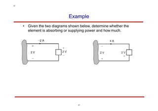
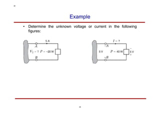
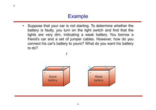
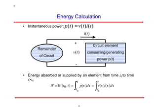
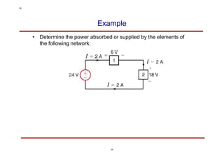
EE-130
Linear Circuit Analysis
Yumna Bilal
Department of Electrical Engineering
University of Gujrat
yumna.bilal@uog.edu.pk
1
1
Course Material
• Lecture notes
• Textbook:
Basic Engineering Circuit Analysis, 11th
edition by J. David Irwin and R. Mark Nelms.
John Wiley & Sons.
2
2
Motivation
Electrical circuits seem to be everywhere!
3
3
What is an Electric Circuit?
• In electrical engineering, we are usually interested in transferring
energy or communicating signals from one point to another.
To do this, we often require an interconnection of electrical
components.
“An electric circuit is an interconnection of electrical components.”
• Typical circuit or electrical components that we will see in this year:
batteries or voltage sources, current sources, resistors, switches,
capacitors, inductors, diodes, transistors, operational amplifiers, …
4
4
A Simple Circuit
6
6
A More Complicated Circuit
A Radio Receiver
7
7
System of Units
The International System of Units, or Système
International des Unités (SI), also known as metric
system uses 7 mutually independent base units. All other
units are derived units.
SI Base Units
8
8
SI Prefixes
9
9
What is a Circuit?
• According to Merriam-Webster Dictionary:
“The complete path of an electric current including usually the source of
electric energy.”
• According to Encyclopedia Britannica:
“Path that transmits electric current.”
“A circuit includes a battery or a generator that gives energy to the
charged particles; devices that use current, such as lamps, motors, or
electronic computers; and connecting wires or transmission lines.
Circuits can be classified according to the type of current they carry
(see alternating current, direct current) or according to whether the
current remains whole (series) or divides to flow through several
branches simultaneously (parallel). Two basic laws that describe the
performance of electric circuits are Ohm's law and Kirchhoff's circuit
rules."
10
10
Charge
• Note that in 1C of charge there are:
1/ 1.602  10 -19 = 6.24  10 18 electrons
• Laboratory values of charges are more likely to be a fraction of a
Coulumb (e.g., pC, nC, C, or mC).
• Law of conservation of charge: charge can neither be created
nor destroyed, only transferred. (This is a law in classical
physics and may not be true in some odd cases!. We are not
dealing with those cases anyway.)
• Electrical effects are attributed to both separation of charges
and/or charges in motion!
11
11
Electric Current (Charges in Motion!)
• Current: net flow of charge across any cross section of a
conductor, measured in Amperes (Andre-Marie Ampere (1775-
1836), a French mathematician and physicist)
• Current can be thought of as the rate of change ofcharge:
i 
dq
dt
12
12
Electric Current
• Originally scientists (in particular Benjamin Franklin (1706-1790)
an American scientist and inventor) thought that current is only
due to the movement of positive charges.
• Thus the direction of the current was considered the direction of
movement of positive charges.
current
13
13
Electric Current
• In reality in metallic conductors current is due to the movement
of electrons, however, we follow the universally accepted
convention that current is in the direction of positive charge
movement.
• Two ways of showing the same current:
14
14
Two Important Types of Current
• Direct current (DC) is a current that remains constant withtime.
• Alternating current (AC) is a current that varies sinusoidally with
time.
15
15
Magnitude of Some Typical Currents
16
16
Voltage (Separation of Charge)
• Voltage (electromotive force, or potential) is the energy required
to move a unit charge through a circuit element, and is
measured in Volts (Alessandro Antonio Volta (1745-1827) an
Italian Physicist).
v 
dW
dq
• Similar to electric current, there are two important types of
voltage: DC and AC
17
17
Typical Voltage Magnitudes
18
18
Voltage
• “Voltage between two points in a circuit is the difference in
energy level of a unit charge located at each of the twopoints.
• Voltage is very similar to a gravitational force.
• Some examples:
19
19
Voltage Polarity
• The plus (+) and minus (-) sign are used to define voltage
polarity.
• The assumption is that the potential of the terminal with (+)
polarity is higher than the potential of the terminal with (-)
polarity by the amount of voltage drop.
• The polarity assignment is somewhat arbitrary! Is this a scientific
statement?!! What do you mean by arbitrary?!!!
20
20
Voltage Polarity
• Figures (a) and (b) are two equivalent representation of the
same voltage:
• Both show that the potential of terminal a is 9V higher than the
potential of terminal b.
21
Hence, when we define either current or
voltage,
it is absolutely necessary that we specify
both magnitude and direction.
21
Power
• The rate of change of (expending or absorbing) energy per unit
time, measured in Watts (James Watt (1736-1819) a Scottish
inventor and mechanical engineer)
p 
dW

dW

dq
 vi
dt dq dt
22
22
A Classification of Circuit Components
• One common classification for circuit components is to group
them in two major groups:
1) Passive components or passive elements
Components or elements that absorb power.
2) Active components or active elements
Components that are not passive! that is, components that
deliver power.
23
23
Passive Sign Convention
• For calculating absorbed power: The power absorbed by any
circuit element with terminals A and B is equal to the voltage
drop from A to B multiplied by the current through the element
from A to B, i.e., P Vab  Iab
a b
+ -
Vab
Iab
•
24
With this convention if P  0, then the element is absorbing
(consuming) power. Otherwise (i.e.,P  0 ) is absorbing negative
power or actually generating (delivering) power.
24
Tellegan’s Theorem
• Principle of Conservation of the Power: The algebraic sum of
the powers absorbed by all elements in a circuit is zero at any
instance of time (ΣP=0). That is, the sum of absorbed powers is
equal to the sum of generated powers at each instance oftime.
• This principle is also known as Tellegan’s theorem. (Bernard
D.H. Tellegan (1900-1990), a Dutch electrical engineer)
• Similarly, one can write the principle of conservation of energy.
25
25
Passive Sign Convention
• Calculate the power absorbed or supplied by each of the
following elements:
26
26
Example
• Given the two diagrams shown below, determine whether the
element is absorbing or supplying power and how much.
27
27
Example
• Determine the unknown voltage or current in the following
figures:
28
28
Example
• Suppose that your car is not starting. To determine whether the
battery is faulty, you turn on the light switch and find that the
lights are very dim, indicating a weak battery. You borrow a
friend's car and a set of jumper cables. However, how do you
connect his car's battery to yours? What do you want his battery
to do?
29
29
Energy Calculation
• Instantaneous power: p(t) v(t)i(t)
i(t)
+
v(t)
t>t0

t t
t
0 0
W W (t0,t) 
t
)i()d
p()d  v(
Remainder
of Circuit
Circuit element
consuming/generating
power p(t)
-
• Energy absorbed or supplied by an element from time t0 to time
30
30
Circuit Elements
• Circuit components can be broadly classified as being either
active or passive.
• An active element is capable of generating energy.
– Example: current or voltage sources
• A passive element is an element that does not generate energy,
however, they can either consume or store energy.
– Example: resistors, capacitors, and inductors
31
31
(Ideal) Voltage and Current Sources
• Independent sources: An (ideal) independent source is an
active element that provides a specified voltage or current that
is independent of other circuit elements and/or how the source
is used in the circuit.
• Symbol for independent voltage source
(a) Used for constant or time-varying voltage
(b) Used for constant voltage (dc)
Question: Plot the v-i characteristic of the above dc source.
32
32
Ideal Voltage and Current Sources
• Equivalent representation of ideal independent current sources
whose current i(t) is maintained under all voltage requirements
of the attached circuit:
• What is the equivalent of the ideal voltage source shown on the
previous slide (Figure (a))?
33
33
Common Voltage and Current Source Labeling
• Is this different from passive sign convention?
• Can we use the passive convention for sources
34
34
Example
• Determine the power absorbed or supplied by the elements of
the following network:
35
35
Ideal Dependent (Controlled) Source
• An ideal dependent (controlled) source is an active element
whose quantity is controlled by a voltage or current of another
circuit element.
• Dependent sources are usually presented by diamond-shaped
symbols:
Dependent (Controlled) Source
• There are four types of dependent sources:
• Voltage-controlled voltage source (VCVS)
+
- s
V (t)= I(t)
V
+
(t)
-
• Current-controlled voltage source (CCVS)
I(t)
Dependent (Controlled) Source
Is(t)= V(t)
V
+
(t)
-
• Voltage-controlled current source (VCCS)
I(t)
• Current-controlled current source (CCCS)
Example: Dependent Source
• In the following circuits, identify the type of dependent sources:
Example: Power Calculation
• Compute the power absorbed or supplied by each component in
the following circuit.
Example
• Use Tellegan’s theorem to find the current I0 in the following
circuit:
Example
• The charge that enters the BOX is shown below. Calculate and
sketch the current flowing into the BOX and the power absorbed
by the BOX between 0 and 10 milliseconds.
Example
• A third-generation iPod® with a 630 mAh Lithium-ion battery is
to be recharged from a high-power USB port supplying 150 mA
of current. At the beginning of the recharge, 7.8 C of charge are
stored in the battery. The recharging process halts when the
stored charge reaches 35.9 C. How long does it take to
recharge the battery?

Chapter 1.pptx hsaduihdsaiudahsiudashuis

  • 1.
    EE-130 Linear Circuit Analysis YumnaBilal Department of Electrical Engineering University of Gujrat yumna.bilal@uog.edu.pk 1 1
  • 2.
    Course Material • Lecturenotes • Textbook: Basic Engineering Circuit Analysis, 11th edition by J. David Irwin and R. Mark Nelms. John Wiley & Sons. 2 2
  • 3.
  • 4.
    What is anElectric Circuit? • In electrical engineering, we are usually interested in transferring energy or communicating signals from one point to another. To do this, we often require an interconnection of electrical components. “An electric circuit is an interconnection of electrical components.” • Typical circuit or electrical components that we will see in this year: batteries or voltage sources, current sources, resistors, switches, capacitors, inductors, diodes, transistors, operational amplifiers, … 4 4
  • 5.
  • 6.
    A More ComplicatedCircuit A Radio Receiver 7 7
  • 7.
    System of Units TheInternational System of Units, or Système International des Unités (SI), also known as metric system uses 7 mutually independent base units. All other units are derived units. SI Base Units 8 8
  • 8.
  • 9.
    What is aCircuit? • According to Merriam-Webster Dictionary: “The complete path of an electric current including usually the source of electric energy.” • According to Encyclopedia Britannica: “Path that transmits electric current.” “A circuit includes a battery or a generator that gives energy to the charged particles; devices that use current, such as lamps, motors, or electronic computers; and connecting wires or transmission lines. Circuits can be classified according to the type of current they carry (see alternating current, direct current) or according to whether the current remains whole (series) or divides to flow through several branches simultaneously (parallel). Two basic laws that describe the performance of electric circuits are Ohm's law and Kirchhoff's circuit rules." 10 10
  • 10.
    Charge • Note thatin 1C of charge there are: 1/ 1.602  10 -19 = 6.24  10 18 electrons • Laboratory values of charges are more likely to be a fraction of a Coulumb (e.g., pC, nC, C, or mC). • Law of conservation of charge: charge can neither be created nor destroyed, only transferred. (This is a law in classical physics and may not be true in some odd cases!. We are not dealing with those cases anyway.) • Electrical effects are attributed to both separation of charges and/or charges in motion! 11 11
  • 11.
    Electric Current (Chargesin Motion!) • Current: net flow of charge across any cross section of a conductor, measured in Amperes (Andre-Marie Ampere (1775- 1836), a French mathematician and physicist) • Current can be thought of as the rate of change ofcharge: i  dq dt 12 12
  • 12.
    Electric Current • Originallyscientists (in particular Benjamin Franklin (1706-1790) an American scientist and inventor) thought that current is only due to the movement of positive charges. • Thus the direction of the current was considered the direction of movement of positive charges. current 13 13
  • 13.
    Electric Current • Inreality in metallic conductors current is due to the movement of electrons, however, we follow the universally accepted convention that current is in the direction of positive charge movement. • Two ways of showing the same current: 14 14
  • 14.
    Two Important Typesof Current • Direct current (DC) is a current that remains constant withtime. • Alternating current (AC) is a current that varies sinusoidally with time. 15 15
  • 15.
    Magnitude of SomeTypical Currents 16 16
  • 16.
    Voltage (Separation ofCharge) • Voltage (electromotive force, or potential) is the energy required to move a unit charge through a circuit element, and is measured in Volts (Alessandro Antonio Volta (1745-1827) an Italian Physicist). v  dW dq • Similar to electric current, there are two important types of voltage: DC and AC 17 17
  • 17.
  • 18.
    Voltage • “Voltage betweentwo points in a circuit is the difference in energy level of a unit charge located at each of the twopoints. • Voltage is very similar to a gravitational force. • Some examples: 19 19
  • 19.
    Voltage Polarity • Theplus (+) and minus (-) sign are used to define voltage polarity. • The assumption is that the potential of the terminal with (+) polarity is higher than the potential of the terminal with (-) polarity by the amount of voltage drop. • The polarity assignment is somewhat arbitrary! Is this a scientific statement?!! What do you mean by arbitrary?!!! 20 20
  • 20.
    Voltage Polarity • Figures(a) and (b) are two equivalent representation of the same voltage: • Both show that the potential of terminal a is 9V higher than the potential of terminal b. 21 Hence, when we define either current or voltage, it is absolutely necessary that we specify both magnitude and direction. 21
  • 21.
    Power • The rateof change of (expending or absorbing) energy per unit time, measured in Watts (James Watt (1736-1819) a Scottish inventor and mechanical engineer) p  dW  dW  dq  vi dt dq dt 22 22
  • 22.
    A Classification ofCircuit Components • One common classification for circuit components is to group them in two major groups: 1) Passive components or passive elements Components or elements that absorb power. 2) Active components or active elements Components that are not passive! that is, components that deliver power. 23 23
  • 23.
    Passive Sign Convention •For calculating absorbed power: The power absorbed by any circuit element with terminals A and B is equal to the voltage drop from A to B multiplied by the current through the element from A to B, i.e., P Vab  Iab a b + - Vab Iab • 24 With this convention if P  0, then the element is absorbing (consuming) power. Otherwise (i.e.,P  0 ) is absorbing negative power or actually generating (delivering) power. 24
  • 24.
    Tellegan’s Theorem • Principleof Conservation of the Power: The algebraic sum of the powers absorbed by all elements in a circuit is zero at any instance of time (ΣP=0). That is, the sum of absorbed powers is equal to the sum of generated powers at each instance oftime. • This principle is also known as Tellegan’s theorem. (Bernard D.H. Tellegan (1900-1990), a Dutch electrical engineer) • Similarly, one can write the principle of conservation of energy. 25 25
  • 25.
    Passive Sign Convention •Calculate the power absorbed or supplied by each of the following elements: 26 26
  • 26.
    Example • Given thetwo diagrams shown below, determine whether the element is absorbing or supplying power and how much. 27 27
  • 27.
    Example • Determine theunknown voltage or current in the following figures: 28 28
  • 28.
    Example • Suppose thatyour car is not starting. To determine whether the battery is faulty, you turn on the light switch and find that the lights are very dim, indicating a weak battery. You borrow a friend's car and a set of jumper cables. However, how do you connect his car's battery to yours? What do you want his battery to do? 29 29
  • 29.
    Energy Calculation • Instantaneouspower: p(t) v(t)i(t) i(t) + v(t) t>t0  t t t 0 0 W W (t0,t)  t )i()d p()d  v( Remainder of Circuit Circuit element consuming/generating power p(t) - • Energy absorbed or supplied by an element from time t0 to time 30 30
  • 30.
    Circuit Elements • Circuitcomponents can be broadly classified as being either active or passive. • An active element is capable of generating energy. – Example: current or voltage sources • A passive element is an element that does not generate energy, however, they can either consume or store energy. – Example: resistors, capacitors, and inductors 31 31
  • 31.
    (Ideal) Voltage andCurrent Sources • Independent sources: An (ideal) independent source is an active element that provides a specified voltage or current that is independent of other circuit elements and/or how the source is used in the circuit. • Symbol for independent voltage source (a) Used for constant or time-varying voltage (b) Used for constant voltage (dc) Question: Plot the v-i characteristic of the above dc source. 32 32
  • 32.
    Ideal Voltage andCurrent Sources • Equivalent representation of ideal independent current sources whose current i(t) is maintained under all voltage requirements of the attached circuit: • What is the equivalent of the ideal voltage source shown on the previous slide (Figure (a))? 33 33
  • 33.
    Common Voltage andCurrent Source Labeling • Is this different from passive sign convention? • Can we use the passive convention for sources 34 34
  • 34.
    Example • Determine thepower absorbed or supplied by the elements of the following network: 35 35
  • 35.
    Ideal Dependent (Controlled)Source • An ideal dependent (controlled) source is an active element whose quantity is controlled by a voltage or current of another circuit element. • Dependent sources are usually presented by diamond-shaped symbols:
  • 36.
    Dependent (Controlled) Source •There are four types of dependent sources: • Voltage-controlled voltage source (VCVS) + - s V (t)= I(t) V + (t) - • Current-controlled voltage source (CCVS) I(t)
  • 37.
    Dependent (Controlled) Source Is(t)=V(t) V + (t) - • Voltage-controlled current source (VCCS) I(t) • Current-controlled current source (CCCS)
  • 38.
    Example: Dependent Source •In the following circuits, identify the type of dependent sources:
  • 39.
    Example: Power Calculation •Compute the power absorbed or supplied by each component in the following circuit.
  • 40.
    Example • Use Tellegan’stheorem to find the current I0 in the following circuit:
  • 41.
    Example • The chargethat enters the BOX is shown below. Calculate and sketch the current flowing into the BOX and the power absorbed by the BOX between 0 and 10 milliseconds.
  • 42.
    Example • A third-generationiPod® with a 630 mAh Lithium-ion battery is to be recharged from a high-power USB port supplying 150 mA of current. At the beginning of the recharge, 7.8 C of charge are stored in the battery. The recharging process halts when the stored charge reaches 35.9 C. How long does it take to recharge the battery?