EE100: Basic ElectricalEngineering
Dept. of Electrical Engineering,
C. V. Raman Global University, Bhubaneswar, Odisha
Dr. Zefree Lazarus Mayaluri
Associate Professor
2.
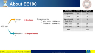
About EE100
BEE 100
Theor
y
Practica
l
5Modules Assessments
Mid sem
End sem
- 20 Marks
- 50 Marks
10 Experiments
Category Marks Weightage
Assignment 10 10
Quiz 60 10
Experiential
Learning
10 10
Mid Sem 20 20
End Sem 100 50
Total 100
Basic Electrical Engineering
2
Dr. M. Z. Lazarus, Associate Prof., EE, CGU, BBSR
3.
3
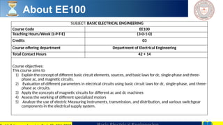
SUBJECT: BASIC ELECTRICALENGINEERING
Course Code EE100
Teaching Hours/Week (L-P-T-E) (3-0-1-0)
Credits 03
Course offering department Department of Electrical Engineering
Total Contact Hours 42 + 14
Course objectives:
This course aims to
1) Explain the concept of different basic circuit elements, sources, and basic laws for dc, single-phase and three-
phase ac, and magnetic circuits.
2) Evaluation of different parameters in electrical circuits using basic circuit laws for dc, single-phase, and three-
phase ac circuits.
3) Apply the concepts of magnetic circuits for different ac and dc machines
4) Assess the working of different specialized motors
5) Analyze the use of electric Measuring instruments, transmission, and distribution, and various switchgear
components in the electrical supply system.
About EE100
4.
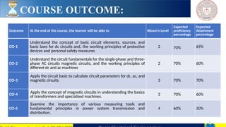
COURSE OUTCOME:
4
Outcome Atthe end of the course, the learner will be able to Bloom’s Level
Expected
proficiency
percentage
Expected
Attainment
percentage
CO-1
Understand the concept of basic circuit elements, sources, and
basic laws for dc circuits and, the working principles of protective
devices and personal safety measures
2 70% 65%
CO-2
Understand the circuit fundamentals for the single-phase and three-
phase AC circuits magnetic circuits, and the working principles of
different dc and ac machines
2 70% 60%
CO-3
Apply the circuit basic to calculate circuit parameters for dc, ac, and
magnetic circuits. 3 70% 70%
CO-4
Apply the concept of magnetic circuits in understanding the basics
of transformers and specialized machines.
3 70% 60%
CO-5
Examine the importance of various measuring tools and
fundamental principles in power system transmission and
distribution.
4 60% 50%
5.
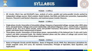
Syllabus
5
Module – 1(10hrs.)
• DC circuits: Ohm’s law and Kirchhoff’s laws, analysis of series, parallel and series-parallel circuits excited by
independent voltage sources. Mesh analysis, Nodal Analysis, Star-Delta and Delta-star conversion, Superposition
theorem, Thevenin’s and Norton’s theorems, and maximum power transfer theorem.
Module – 2 (10hrs.)
• Single-phase circuits: Generation of sinusoidal voltage, frequency of generated voltage, average value, RMS value,
form, and peak factors. Voltage and current relationship, with phasor diagrams, in R, L, and C circuits, j operators.
Analysis of R-L, R-C, R-L-C Series circuits, series and parallel resonance, Real power, reactive power, apparent
power, and Power factor. Measurement of power.
• Three-phase circuits: Generation of three-phase power, representation of the balanced star (3 wire and 4-wire
system) and delta connected loads, the relation between phase and line values of voltage and current from
phasor diagrams, advantages of three-phase systems.
Module – 3 (6 hrs.)
• Basics of Magnetic Circuits and DC Machines: Basics of Magnetic circuit, MMF, Flux, Reluctance calculations for
simple magnetic cores, B-H curve, DC machines Construction, Principle of Operation, Basic Equations, and
Applications
6.
6
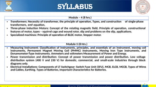
Module – 4(8 hrs.)
• Transformers: Necessity of transformer, the principle of operation, Types, and construction of single-phase
transformers, emf equation,
• Three-phase induction Motors: Concept of the rotating magnetic field, Principle of operation, constructional
features of motor, types – squirrel cage and wound rotor, slip and problems on the slip, applications.
• Specialized machines: Principle of operation of BLDC motor, Stepper motor.
Module-5 (8 Hrs.)
• Measuring Instrument: Classification of instruments, principles, and essentials of an instrument, moving coil
instruments, Permanent Magnet Moving Coil (PMMC) Instruments, Moving Iron Type instruments, and
Dynamometer-Type Instruments. Ammeters and voltmeters Measurement of Power and Energy.
• Power transmission and distribution: Concept of power transmission and power distribution. Low voltage
distribution system (400 V and 230 V) for domestic, commercial, and small-scale industries through block
diagrams only.
• Electrical Installations: Components of LT Switchgear: Switch Fuse Unit (SFU), MCB, ELCB, MCCB, Types of Wires
and Cables, Earthing. Types of Batteries, Important Characteristics for Batteries.
Syllabus
7.
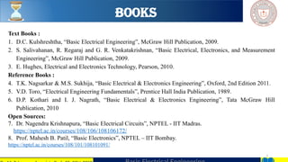
BOOKS
7
Text Books :
1.D.C. Kulshreshtha, “Basic Electrical Engineering”, McGraw Hill Publication, 2009.
2. S. Salivahanan, R. Regaraj and G. R. Venkatakrishnan, “Basic Electrical, Electronics, and Measurement
Engineering”, McGraw Hill Publication, 2009.
3. E. Hughes, Electrical and Electronics Technology, Pearson, 2010.
Reference Books :
4. T.K. Nagsarkar & M.S. Sukhija, “Basic Electrical & Electronics Engineering”, Oxford, 2nd Edition 2011.
5. V.D. Toro, “Electrical Engineering Fundamentals”, Prentice Hall India Publication, 1989.
6. D.P. Kothari and I. J. Nagrath, “Basic Electrical & Electronics Engineering”, Tata McGraw Hill
Publication, 2010
Open Sources:
7. Dr. Nagendra Krishnapura, “Basic Electrical Circuits”, NPTEL - IIT Madras.
https://nptel.ac.in/courses/108/106/108106172/
8. Prof. Mahesh B. Patil, “Basic Electronics”, NPTEL – IIT Bombay.
https://nptel.ac.in/courses/108/101/108101091/
11
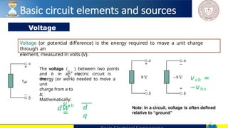
Voltage
Voltage (or potentialdifference) is the energy required to move a unit charge
through an
element, measured in volts (V).
The voltage
𝑣𝑎
𝑏
between two points
a
and b in an electric circuit is
the
Note: In a circuit, voltage is often defined
relative to “ground”
𝑣𝑎𝑏
=
energy (or work) needed to move a
unit
charge from a to
b;
Mathematically:
𝑑𝑊 𝑑
𝑞
𝑣𝑎𝑏 =
−𝑣𝑏𝑎
Basic circuit elements and sources
12.
12
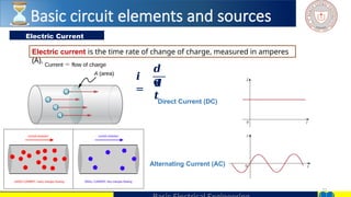
Electric Current
Electric currentis the time rate of change of charge, measured in amperes
(A).
𝒊
=
𝒅
𝒒
𝒅
𝒕Direct Current (DC)
Alternating Current (AC)
Basic circuit elements and sources
13.
13
𝒅
𝒘
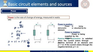
𝒑 =
𝑝
=
∗
𝒅𝒕
𝑑𝑤
𝑑𝑞
𝑑𝑞
𝑑𝑡
𝑝 =𝑣𝑖 = 𝑖2𝑅
=
𝑣2
�
�
Power is positive :
Power is being
deliveredto or absorbed by the
element.
Power is negative:
Power is being
supplied by the
element.
Passive sign convention is satisfied
when the current enters through
the
positive terminal of an element and
p = +vi. If the current enters through the
negative terminal, p = -vi.
Powe
r
Power is the rate of change of energy, measured in watts
(W)
Basic circuit elements and sources
14.
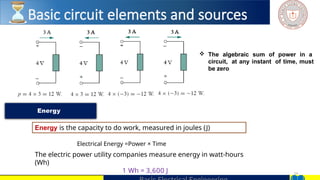
14
The algebraicsum of power in a
circuit, at any instant of time, must
be zero
Energy
Energy is the capacity to do work, measured in joules (J)
Electrical Energy =Power × Time
The electric power utility companies measure energy in watt-hours
(Wh)
1 Wh = 3,600 J
Basic circuit elements and sources
15.
15
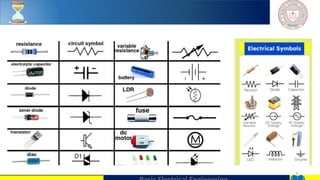
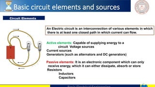
Circuit Elements
An Electriccircuit is an interconnection of various elements in which
there is at least one closed path in which current can flow.
Active elements: Capable of supplying energy to a
circuit Voltage sources
Current sources
Generators (such as alternators and DC generators)
Passive elements: It is an electronic component which can only
receive energy, which it can either dissipate, absorb or store
Resistors
Inductors
Capacitors
Basic circuit elements and sources
17
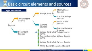
Type of Sources
Sources
Independent
Sources
Dependent
Sources
Current
Sources
IdealVoltage
Sources
Voltage Sources
Practical Voltage
Sources
Ideal Current
Sources
Practical Current
Sources
Voltage Controlled Voltage Source
(VCVS)
Current Controlled Voltage Source
(CCVS)
Voltage Controlled Current Source
(VCCS) Current Controlled Current
Source (CCCS)
Basic circuit elements and sources
18.
18
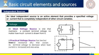
Independent Sources
An idealindependent source is an active element that provides a specified voltage
or current that is completely independent of other circuit variables.
An Ideal Voltage Source is one that
maintains a constant terminal voltage, no
matter how much current is drawn from it.
RL
V
S
V
R
I
V
I
A Practical Voltage Source has low but
finite
internal resistance (Rint) that causes
its terminal voltage to decrease when load
current is increased and vice-versa.
RL
Rint
V
I
V
I
Voltage
source
Basic circuit elements and sources
19.
19
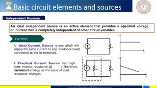
Independent Sources
An idealindependent source is an active element that provides a specified voltage
or current that is completely independent of other circuit variables.
An Ideal Current Source is one which will
supply the same current to any resistance (load)
connected across its terminals.
A Practical Current Source has high
but int
finite internal resistance (R ). Therefore,
the load
current will change as the value of load
resistance changes.
RL
I
I
V
I
V
RL
I
Rint
Current
source
Basic circuit elements and sources
20.
20
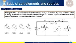
Dependent Sources
The specialkind of sources in which the source voltage or current depends on some other
quantity in the circuit which may be either a voltage or a current anywhere in the circuit are
called Dependent sources or Controlled sources.
Basic circuit elements and sources
21.
21
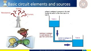
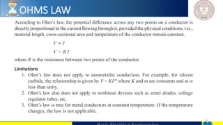
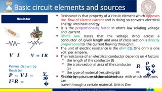
♦ Resistance isthat property of a circuit element which opposes
the flow of electric current and in doing so converts electrical
energy into heat energy.
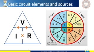
♦ It is the proportionality factor in ohm’s law relating voltage
and current.
♦ Ohm’s law states that the voltage drop across a
conductor of given length and area of cross section is directly
proportional to the current flowing through it.
♦ The unit of electric resistance is the ohm (Ω). One ohm is one
volt per ampere.
♦ The resistance of an electrical conductor depends on 4 factors
the length of the conductor (l)
the cross-sectional area of the conductor
(a)
the type of material (resistivity (ρ))
the temperature of the material
♦ Resistivity is a measure of the ease with which electrons
can
travel through a certain material. Unit is Ω-m
Resistor
𝑹
=
𝝆
𝒍
�
�
�
�
𝑽 𝑰 𝑽 = 𝑰𝑹
Power Drawn by
Resistor
𝑷 = 𝑽𝑰 =
𝑰𝟐𝑹 =
𝑽
𝟐
�
�
Basic circuit elements and sources
22.
22
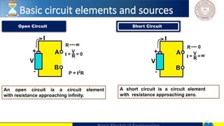
Open Circuit ShortCircuit
A short circuit is a circuit element
with resistance approaching zero.
An open circuit is a circuit element
with resistance approaching infinity.
Basic circuit elements and sources
27
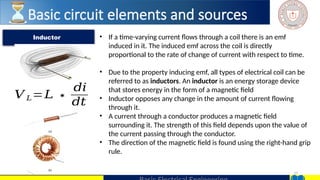
• If atime-varying current flows through a coil there is an emf
induced in it. The induced emf across the coil is directly
proportional to the rate of change of current with respect to time.
• Due to the property inducing emf, all types of electrical coil can be
referred to as inductors. An inductor is an energy storage device
that stores energy in the form of a magnetic field
• Inductor opposes any change in the amount of current flowing
through it.
• A current through a conductor produces a magnetic field
surrounding it. The strength of this field depends upon the value of
the current passing through the conductor.
• The direction of the magnetic field is found using the right-hand grip
rule.
Inductor
Basic circuit elements and sources
𝑉 𝐿=𝐿 ∗
𝑑𝑖
𝑑𝑡
28.
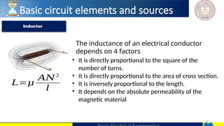
28
The inductance ofan electrical conductor
depends on 4 factors
• It is directly proportional to the square of the
number of turns.
• It is directly proportional to the area of cross section.
• It is inversely proportional to the length.
• It depends on the absolute permeability of the
magnetic material
Inductor
𝐿=𝜇
𝐴𝑁2
𝑙
Basic circuit elements and sources
29.
29
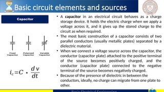
• A capacitorin an electrical circuit behaves as a charge
storage device. It holds the electric charge when we apply a
voltage across it, and it gives up the stored charge to the
circuit as when required.
• The most basic construction of a capacitor consists of two
parallel conductors (usually metallic plates) separated by a
dielectric material.
• When we connect a voltage source across the capacitor, the
conductor (capacitor plate) attached to the positive terminal
of the source becomes positively charged, and the
conductor (capacitor plate) connected to the negative
terminal of the source becomes negatively charged.
• Because of the presence of dielectric in between the
conductors, ideally, no charge can migrate from one plate to
other.
Capacitor
𝑖𝑐 =𝐶∗
𝑑 𝑣
𝑑𝑡
Basic circuit elements and sources
30.
30
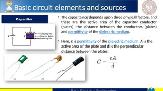
• The capacitancedepends upon three physical factors, and
these are the active area of the capacitor conductor
(plates), the distance between the conductors (plates)
and permittivity of the dielectric medium.
• Here, ε is permittivity of the dielectric medium, A is the
active area of the plate and d is the perpendicular
distance between the plates.
Capacitor
Basic circuit elements and sources


![UNIT-I Final (1)[1].pptfgcvhvjgbjhbjgbjhhvhvhvh](https://cdn.slidesharecdn.com/ss_thumbnails/unit-ifinal11-251129122433-e786871d-thumbnail.jpg?width=640&height=640&fit=bounds)