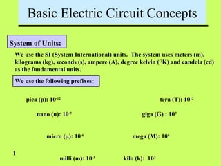
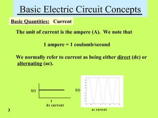
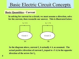
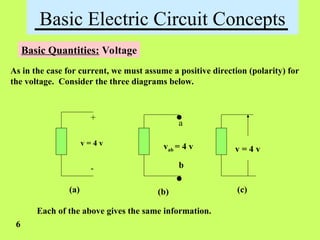
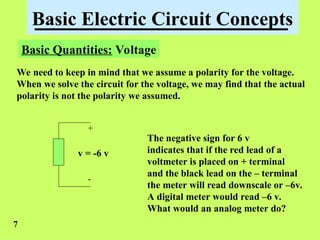
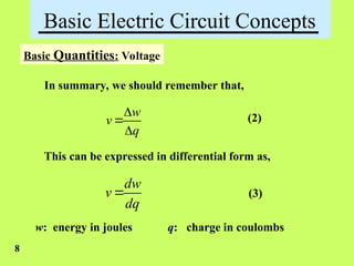
Basic Laws of Electric Circuits
Fundamentals
Lesson 1
Basic Electric Circuit Concepts
System of Units:
We use the SI (System International) units. The system uses meters (m),
kilograms (kg), seconds (s), ampere (A), degree kelvin (O
K) and candela (cd)
as the fundamental units.
We use the following prefixes:
pica (p): 10-12
nano (n): 10-9
micro (): 10-6
milli (m): 10-3
tera (T): 1012
giga (G) : 109
mega (M): 106
kilo (k): 103
1
Basic Electric Circuit Concepts
What is electricity?
One might define electricity as the separation of positive and
negative electric charge. (see slide note)
When the charges are separated and stationary we call this
static electricity. The charging of a capacitor is an example.
The separation of charge between clouds and the earth before
a lighting discharge is a static electricity.
When the charges are in motion (changing with time relative
to one another) we have variable electricity.
2
Basic Electric Circuit Concepts
Basic Quantities: Current
The unit of current is the ampere (A). We note that
1 ampere = 1 coulomb/second
We normally refer to current as being either direct (dc) or
alternating (ac).
i(t) i(t)
t t
dc current
ac current
0 0.5 1 1.5 2 2.5 3 3.5
-1
-0.8
-0.6
-0.4
-0.2
0
0.2
0.4
0.6
0.8
1
ac current
3
Basic Electric Circuit Concepts
Basic Quantities: Current
In solving for current in a circuit, we must assume a direction, solve
for the current, then reconcile our answer. This is illustrated below.
C irc uit 1 C irc uit 2
(a) (b)
I1 = 4 A I2 = - 3 A
In the diagram above, current I1 is actually 4 A as assumed. The
actual positive direction of current I2 (equal to -3 A) in the opposite
direction of the arrow for I2.
4
Basic Electric Circuit Concepts
Basic Quantities: Voltage
The next quantity of interest is voltage. Voltage is also called an
electromotive force (emf). It is also called potential (coming from
the expression, “potential energy.” However, voltage is not energy.)
Suppose one coulomb of charge is located at point b and one joule
of energy is required to move the charge to point a. Then we say
that Vab = 1 volt = 1 joule/coulomb = 1 newton.meter/coulomb.
Vab = 1 volt states that the potential of point a (voltage at point a)
is l volt (positive) with respect to point b.
The sign associated with a voltage is also called its polarity.
5
Basic Electric Circuit Concepts
Basic Quantities: Voltage
As in the case for current, we must assume a positive direction (polarity) for
the voltage. Consider the three diagrams below.
+
-
.
.
v = 4 v
a
b
vab = 4 v v = 4 v
(a) (b) (c)
Each of the above gives the same information.
6
Basic Electric Circuit Concepts
Basic Quantities: Voltage
We need to keep in mind that we assume a polarity for the voltage.
When we solve the circuit for the voltage, we may find that the actual
polarity is not the polarity we assumed.
+
-
v = -6 v
The negative sign for 6 v
indicates that if the red lead of a
voltmeter is placed on + terminal
and the black lead on the – terminal
the meter will read downscale or –6v.
A digital meter would read –6 v.
What would an analog meter do?
7
Basic Electric Circuit Concepts
Basic Quantities: Voltage
In summary, we should remember that,
w
v
q



(2)
This can be expressed in differential form as,
dw
v
dq
 (3)
8
w: energy in joules q: charge in coulombs
Basic Electric Circuit Concepts
Basic Quantities: Power
Power is defined as the time rate of change of doing work. We
express this as,
dw
p
dt
 (3)
We can write equation (3) as follows:
dw dq
p vi
dq dt
  (4)
9
Power has units of watts.
Basic Electric Circuit Concepts
Basic Quantities: Power
In any closed electric circuit, power is both supplied and absorbed.
The amount that is supplied must be equal to the amount that is
absorbed.
Stated another way, we can say that the law of conversation of
energy must hold. Therefore, in any electric circuit the algebraic
sum of the power must be zero.
0
p
  (5)
10
Basic Electric Circuit Concepts
Basic Quantities: Power and Energy
When we pay our electric bills we pay for (watt)(hours) but
because this is such as large number we usually think kWH.
Cost of 1 kWH is approx. 4 – 8 cents.
A profile of the power you use during a day may be as shown below.
p
t
The energy we pay for is the area under the power-time curve.
o
t t
o
t t
w pdt vidt
 
  (6)
11
Basic Electric Circuit Concepts
Basic Quantities: Power
We adopt a passive sign convention in order to define the sign of
supplied power and the sign of absorbed power. Consider the following.
load
source
I
+
_
vs
+
_
vL
Power supplied: If the assumed direction of the current leaves
the assumed positive polarity of the voltage, power is supplied.
Power absorbed: If the assumed direction of the current enters
the assumed positive polarity of the voltage, power is absorbed.
12
Basic Electric Circuit Concepts
Basic Quantities: Charge
Charge is the most fundamental quantity of electric circuits. In most
electric circuits, the basic charge is that of an electron, which is
-1.602x10⁻¹⁹
coulombs (C).
The entity, charge, is expressed as Q or q. If the charge is constant
we use Q. If the charge is in motion we use q(t) or q.
According to fundamental laws, charge cannot be either created or
destroyed, only transferred from one point to another.
We define charge in motion as current. That is,
( )
dq
i t
dt
 (7)
13
Basic Electric Circuit Concepts
Basic Quantities: Power
We consider the following examples:
_
+
v = 5 v
+
-
v = 5 v
+
v = 5 v
_
+
v = 5 v
I=4A I=4A I=4A I=4A
(a) P = 20W (b) P = 20W (c) P = -20W (d) P = -20W
absorbed absorbed absorbed absorbed
14
Basic Electric Circuit Concepts
Circuit Elements:
We classify circuit elements as passive and active.
Passive elements cannot generate energy. Common examples of
passive elements are resistors, capacitors and inductors. We will
see later than capacitors and inductors can store energy but cannot
generate energy.
Active elements can generate energy. Common examples of active
elements are power supplies, batteries, operational amplifiers.
For the present time we will be concerned only with sources. The types
of sources we consider are independent and dependent.
15
Basic Electric Circuit Concepts
Circuit Elements: Ideal independent voltage source
An ideal dependent voltage source is characterized as having a
constant voltage across its terminals, regardless of the load
connected to the terminals.
The ideal voltage source can supply any amount of current.
Furthermore, the ideal independent voltage source can supply any
amount of power.
The standard symbols of the ideal independent voltage source are
shown below.
+
_
v(t) E
Sometimes
used
Most often
used
16
Basic Electric Circuit Concepts
Circuit Elements: Ideal independent current sources
An ideal independent current source is characterized as
providing a constant value of current, regardless of the load.
If the current source is truly ideal, it can provided any value
of voltage and any amount of power.
The standard symbol used for the ideal independent current
source is shown below.
i(t)
17
1 meg 
1 amp
+
-
V
V = ?
Basic Electric Circuit Concepts
Circuit Elements: Comments about ideal model
The ideal independent voltage and current sources are models.
As such, they are subject to limitations.
For example, an independent voltage source, that one commonly
works with, cannot put-out 1x10320
volts.
Neither can an ordinary independent current source put out
4x10765
amps.
We must always keep these limitations in mind. Otherwise one
might think that one could start an automobile engine with a
12 V radio battery!
18
Basic Electric Circuit Concepts
Circuit Elements: Dependent voltage source
A dependent voltage source is characterized by depending on
a voltage or current somewhere else in the circuit. The symbol
For the current source is shown below. Note the diamond shape.
A circuit containing a dependent voltage source is shown below.
10  20 
30 
12 
+
_
5 V
Iy
10Iy
A circuit with a current
controlled dependent
voltage source.
19
Basic Electric Circuit Concepts
Circuit Elements: Dependent current source
A dependent current source is characterized by depending on
a voltage or current somewhere else in the circuit. The symbol
for a dependent current source is shown as follows:
A circuit containing a dependent current source is shown below.
10  20 
30 
12 
+
5 V
+
_
v x
4vx
_
A circuit with a voltage
controlled dependent
current source
20
Basic Electric Circuit Concepts
Current, Charge Examples:
Background:
We have seen that,
( )
dq
i t
dt

It follows that,
0
( ) ( ) (0)
t
q t i t dt q
 

(7)
(8)
21
Basic Electric Circuit Concepts
Current, Charge Examples:
Find the current in a element if the charge flowing through
the element is q(t) = 3t3
+ 6t2
+8t –4.
3 2
(3 6 8 4)
( )
dq d t t t
i t
dt dt
  
 
It follows that,
2
( ) 9 12 8
i t t t
  
22
Basic Electric Circuit Concepts
Current, Charge Examples:
If the current in an electrical device is given by,
i(t) = 2t + 4
With q(0) = 1.5 C
Find the charge flowing through the device.
From Eq. (8) we have,
0 0
( ) ( ) (0) (2 4) 1.5
t t
q t i t dt q t dt
    
 
2
( ) 4 1.5
q t t t
  
23
Basic Electric Circuit Concepts
Power Balance Examples:
You are given the circuit shown below.
20 V
+
_
24 V +
_
0.5Ix
_
8 V
+ _
Ix = 4 A
+
_
4 V
2 A
0
p
 
(a) Calculate the power supplied by each device.
(b) Show that the
(c) Verify that Psup = Pabs = 104 W
24
Basic Electric Circuit Concepts
Power Balance Examples:
0
8
40
;
32
32
8
4
;
96
4
24
sup
4
sup
20
sup
5
.
0
sup
8
sup
24
sup













P
w
P
w
P
w
P
w
x
P
w
x
P
v
v
x
I
v
Basic Electric Circuit Concepts
End of Lesson 1
circuits
Fundamentals

BASIC ELECTRICAL Lesson 1 Fundamentals.ppt

  • 1.
    Basic Laws ofElectric Circuits Fundamentals Lesson 1
  • 2.
    Basic Electric CircuitConcepts System of Units: We use the SI (System International) units. The system uses meters (m), kilograms (kg), seconds (s), ampere (A), degree kelvin (O K) and candela (cd) as the fundamental units. We use the following prefixes: pica (p): 10-12 nano (n): 10-9 micro (): 10-6 milli (m): 10-3 tera (T): 1012 giga (G) : 109 mega (M): 106 kilo (k): 103 1
  • 3.
    Basic Electric CircuitConcepts What is electricity? One might define electricity as the separation of positive and negative electric charge. (see slide note) When the charges are separated and stationary we call this static electricity. The charging of a capacitor is an example. The separation of charge between clouds and the earth before a lighting discharge is a static electricity. When the charges are in motion (changing with time relative to one another) we have variable electricity. 2
  • 4.
    Basic Electric CircuitConcepts Basic Quantities: Current The unit of current is the ampere (A). We note that 1 ampere = 1 coulomb/second We normally refer to current as being either direct (dc) or alternating (ac). i(t) i(t) t t dc current ac current 0 0.5 1 1.5 2 2.5 3 3.5 -1 -0.8 -0.6 -0.4 -0.2 0 0.2 0.4 0.6 0.8 1 ac current 3
  • 5.
    Basic Electric CircuitConcepts Basic Quantities: Current In solving for current in a circuit, we must assume a direction, solve for the current, then reconcile our answer. This is illustrated below. C irc uit 1 C irc uit 2 (a) (b) I1 = 4 A I2 = - 3 A In the diagram above, current I1 is actually 4 A as assumed. The actual positive direction of current I2 (equal to -3 A) in the opposite direction of the arrow for I2. 4
  • 6.
    Basic Electric CircuitConcepts Basic Quantities: Voltage The next quantity of interest is voltage. Voltage is also called an electromotive force (emf). It is also called potential (coming from the expression, “potential energy.” However, voltage is not energy.) Suppose one coulomb of charge is located at point b and one joule of energy is required to move the charge to point a. Then we say that Vab = 1 volt = 1 joule/coulomb = 1 newton.meter/coulomb. Vab = 1 volt states that the potential of point a (voltage at point a) is l volt (positive) with respect to point b. The sign associated with a voltage is also called its polarity. 5
  • 7.
    Basic Electric CircuitConcepts Basic Quantities: Voltage As in the case for current, we must assume a positive direction (polarity) for the voltage. Consider the three diagrams below. + - . . v = 4 v a b vab = 4 v v = 4 v (a) (b) (c) Each of the above gives the same information. 6
  • 8.
    Basic Electric CircuitConcepts Basic Quantities: Voltage We need to keep in mind that we assume a polarity for the voltage. When we solve the circuit for the voltage, we may find that the actual polarity is not the polarity we assumed. + - v = -6 v The negative sign for 6 v indicates that if the red lead of a voltmeter is placed on + terminal and the black lead on the – terminal the meter will read downscale or –6v. A digital meter would read –6 v. What would an analog meter do? 7
  • 9.
    Basic Electric CircuitConcepts Basic Quantities: Voltage In summary, we should remember that, w v q    (2) This can be expressed in differential form as, dw v dq  (3) 8 w: energy in joules q: charge in coulombs
  • 10.
    Basic Electric CircuitConcepts Basic Quantities: Power Power is defined as the time rate of change of doing work. We express this as, dw p dt  (3) We can write equation (3) as follows: dw dq p vi dq dt   (4) 9 Power has units of watts.
  • 11.
    Basic Electric CircuitConcepts Basic Quantities: Power In any closed electric circuit, power is both supplied and absorbed. The amount that is supplied must be equal to the amount that is absorbed. Stated another way, we can say that the law of conversation of energy must hold. Therefore, in any electric circuit the algebraic sum of the power must be zero. 0 p   (5) 10
  • 12.
    Basic Electric CircuitConcepts Basic Quantities: Power and Energy When we pay our electric bills we pay for (watt)(hours) but because this is such as large number we usually think kWH. Cost of 1 kWH is approx. 4 – 8 cents. A profile of the power you use during a day may be as shown below. p t The energy we pay for is the area under the power-time curve. o t t o t t w pdt vidt     (6) 11
  • 13.
    Basic Electric CircuitConcepts Basic Quantities: Power We adopt a passive sign convention in order to define the sign of supplied power and the sign of absorbed power. Consider the following. load source I + _ vs + _ vL Power supplied: If the assumed direction of the current leaves the assumed positive polarity of the voltage, power is supplied. Power absorbed: If the assumed direction of the current enters the assumed positive polarity of the voltage, power is absorbed. 12
  • 14.
    Basic Electric CircuitConcepts Basic Quantities: Charge Charge is the most fundamental quantity of electric circuits. In most electric circuits, the basic charge is that of an electron, which is -1.602x10⁻¹⁹ coulombs (C). The entity, charge, is expressed as Q or q. If the charge is constant we use Q. If the charge is in motion we use q(t) or q. According to fundamental laws, charge cannot be either created or destroyed, only transferred from one point to another. We define charge in motion as current. That is, ( ) dq i t dt  (7) 13
  • 15.
    Basic Electric CircuitConcepts Basic Quantities: Power We consider the following examples: _ + v = 5 v + - v = 5 v + v = 5 v _ + v = 5 v I=4A I=4A I=4A I=4A (a) P = 20W (b) P = 20W (c) P = -20W (d) P = -20W absorbed absorbed absorbed absorbed 14
  • 16.
    Basic Electric CircuitConcepts Circuit Elements: We classify circuit elements as passive and active. Passive elements cannot generate energy. Common examples of passive elements are resistors, capacitors and inductors. We will see later than capacitors and inductors can store energy but cannot generate energy. Active elements can generate energy. Common examples of active elements are power supplies, batteries, operational amplifiers. For the present time we will be concerned only with sources. The types of sources we consider are independent and dependent. 15
  • 17.
    Basic Electric CircuitConcepts Circuit Elements: Ideal independent voltage source An ideal dependent voltage source is characterized as having a constant voltage across its terminals, regardless of the load connected to the terminals. The ideal voltage source can supply any amount of current. Furthermore, the ideal independent voltage source can supply any amount of power. The standard symbols of the ideal independent voltage source are shown below. + _ v(t) E Sometimes used Most often used 16
  • 18.
    Basic Electric CircuitConcepts Circuit Elements: Ideal independent current sources An ideal independent current source is characterized as providing a constant value of current, regardless of the load. If the current source is truly ideal, it can provided any value of voltage and any amount of power. The standard symbol used for the ideal independent current source is shown below. i(t) 17 1 meg  1 amp + - V V = ?
  • 19.
    Basic Electric CircuitConcepts Circuit Elements: Comments about ideal model The ideal independent voltage and current sources are models. As such, they are subject to limitations. For example, an independent voltage source, that one commonly works with, cannot put-out 1x10320 volts. Neither can an ordinary independent current source put out 4x10765 amps. We must always keep these limitations in mind. Otherwise one might think that one could start an automobile engine with a 12 V radio battery! 18
  • 20.
    Basic Electric CircuitConcepts Circuit Elements: Dependent voltage source A dependent voltage source is characterized by depending on a voltage or current somewhere else in the circuit. The symbol For the current source is shown below. Note the diamond shape. A circuit containing a dependent voltage source is shown below. 10  20  30  12  + _ 5 V Iy 10Iy A circuit with a current controlled dependent voltage source. 19
  • 21.
    Basic Electric CircuitConcepts Circuit Elements: Dependent current source A dependent current source is characterized by depending on a voltage or current somewhere else in the circuit. The symbol for a dependent current source is shown as follows: A circuit containing a dependent current source is shown below. 10  20  30  12  + 5 V + _ v x 4vx _ A circuit with a voltage controlled dependent current source 20
  • 22.
    Basic Electric CircuitConcepts Current, Charge Examples: Background: We have seen that, ( ) dq i t dt  It follows that, 0 ( ) ( ) (0) t q t i t dt q    (7) (8) 21
  • 23.
    Basic Electric CircuitConcepts Current, Charge Examples: Find the current in a element if the charge flowing through the element is q(t) = 3t3 + 6t2 +8t –4. 3 2 (3 6 8 4) ( ) dq d t t t i t dt dt      It follows that, 2 ( ) 9 12 8 i t t t    22
  • 24.
    Basic Electric CircuitConcepts Current, Charge Examples: If the current in an electrical device is given by, i(t) = 2t + 4 With q(0) = 1.5 C Find the charge flowing through the device. From Eq. (8) we have, 0 0 ( ) ( ) (0) (2 4) 1.5 t t q t i t dt q t dt        2 ( ) 4 1.5 q t t t    23
  • 25.
    Basic Electric CircuitConcepts Power Balance Examples: You are given the circuit shown below. 20 V + _ 24 V + _ 0.5Ix _ 8 V + _ Ix = 4 A + _ 4 V 2 A 0 p   (a) Calculate the power supplied by each device. (b) Show that the (c) Verify that Psup = Pabs = 104 W 24
  • 26.
    Basic Electric CircuitConcepts Power Balance Examples: 0 8 40 ; 32 32 8 4 ; 96 4 24 sup 4 sup 20 sup 5 . 0 sup 8 sup 24 sup              P w P w P w P w x P w x P v v x I v
  • 27.
    Basic Electric CircuitConcepts End of Lesson 1 circuits Fundamentals

Editor's Notes

  • #3  Defining electricity is sort of like defining a force. We know what a force does just as we know what electricity does but it is a little difficult to define either at a simple level. In this first course of circuits we will not go into deep understanding of definitions.
  • #20 We can have current controlled dependent voltage sources and voltage controlled dependent voltage sources.
  • #21 You can have current controlled dependent current sources and voltage controlled dependent current sources.