Downloaded 592 times
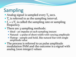
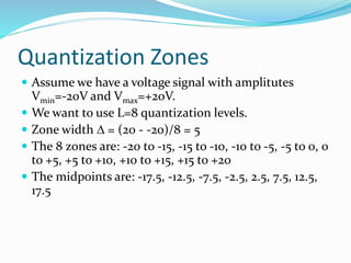
![Digital Filtering
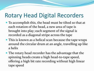
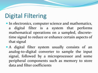
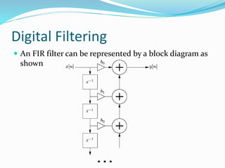
Digital filters are commonplace and an essential
element of everyday electronics such as radios,
cellphones, and stereo receivers
Digital filters are defined by their impulse response,
h[n], or the filter output given a unit sample impulse
input signal
A discrete-time unit impulse signal is defined by](https://image.slidesharecdn.com/avschapter3-140430073706-phpapp01/85/Digital-audio-28-320.jpg)
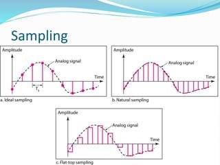
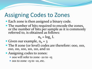
![Digital Filtering
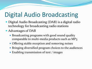
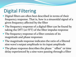
The filter implementation simply performs a
convolution of the time domain impulse response and
the sampled signal
Convolution is defined as the integral of the product of
the two functions after one is reversed and shifted or
delayed
What happens when we add a signal to a one-sample
delayed version of itself?
y[n] = x[n] + x[n - 1]](https://image.slidesharecdn.com/avschapter3-140430073706-phpapp01/85/Digital-audio-30-320.jpg)
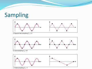
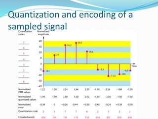
![Digital Filtering
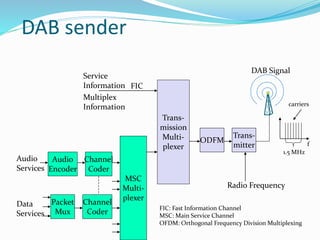
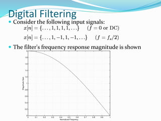
What happens if we use a previous filter output value
to produce the filter's current output?
y[n] = x[n] + y[n - 1]
Consider the following input signals](https://image.slidesharecdn.com/avschapter3-140430073706-phpapp01/85/Digital-audio-34-320.jpg)

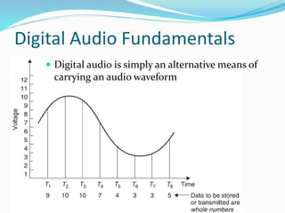
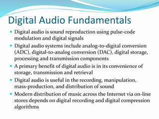
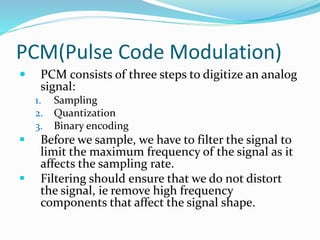
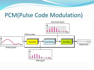
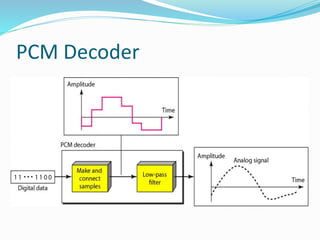
The document provides a comprehensive overview of digital audio fundamentals, including concepts such as sampling, quantization, compression, and digital broadcasting. It explains the process of pulse-code modulation (PCM), detailing the steps involved in converting analog signals to digital formats and the importance of filters in maintaining signal quality. Additionally, it discusses advanced techniques in audio technologies, including rotary head digital recorders, digital filtering, and the implementation of multichannel sound systems.


![Acoustics [Microphones]](https://cdn.slidesharecdn.com/ss_thumbnails/acousticsfinalfinal-190716163521-thumbnail.jpg?width=640&height=640&fit=bounds)