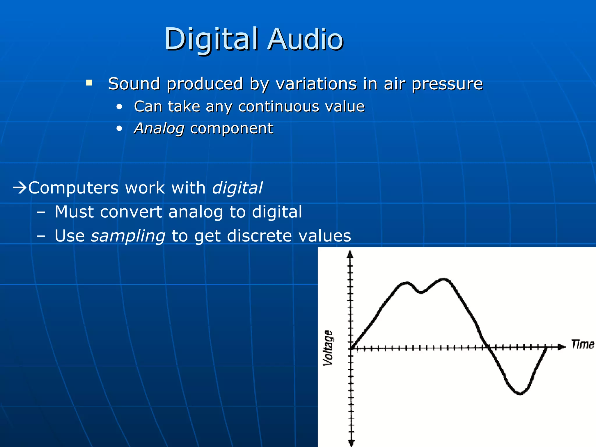
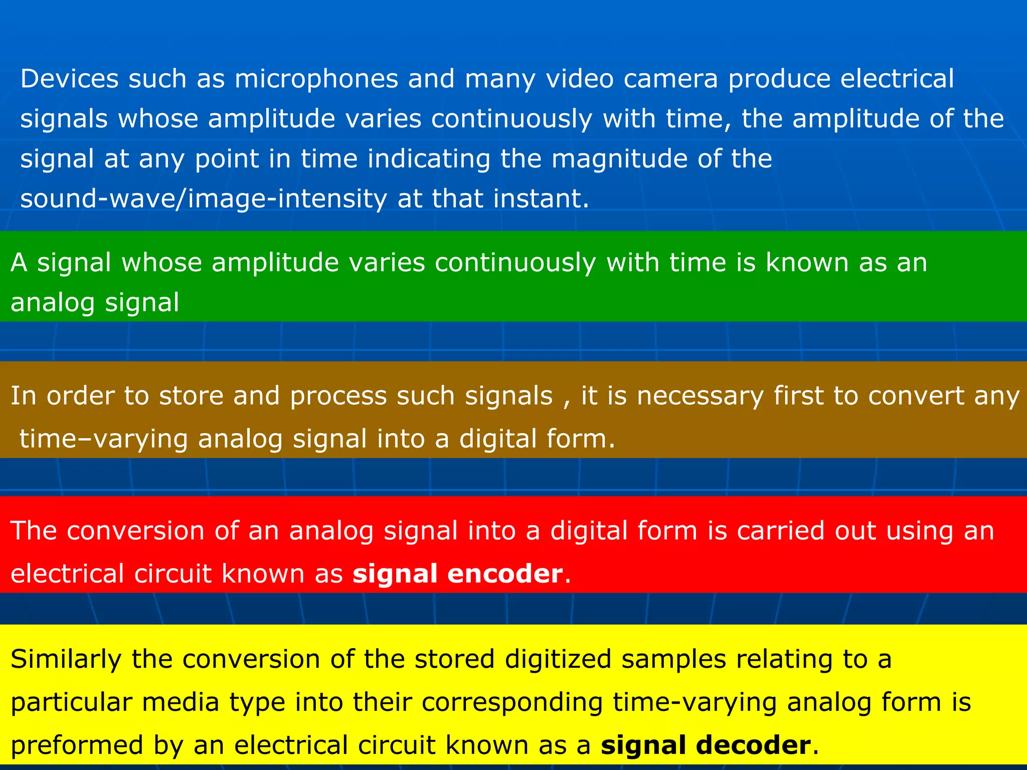
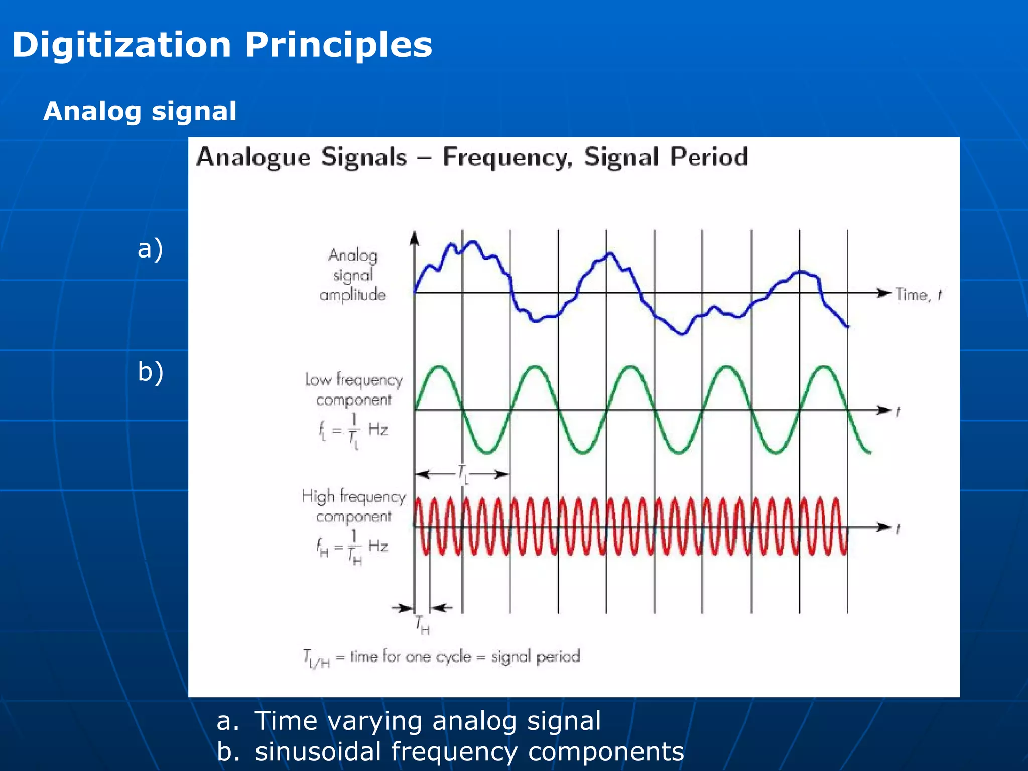
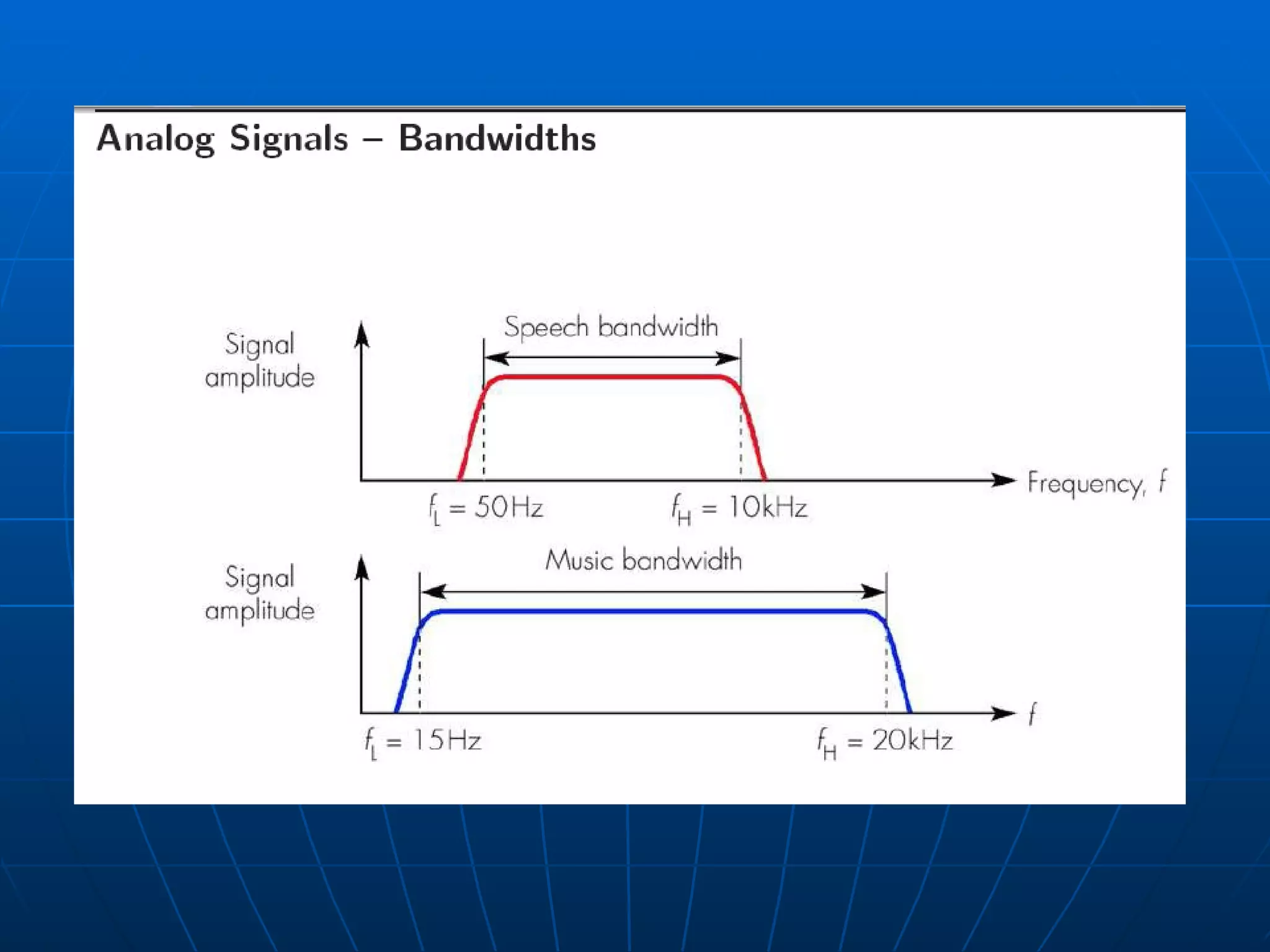
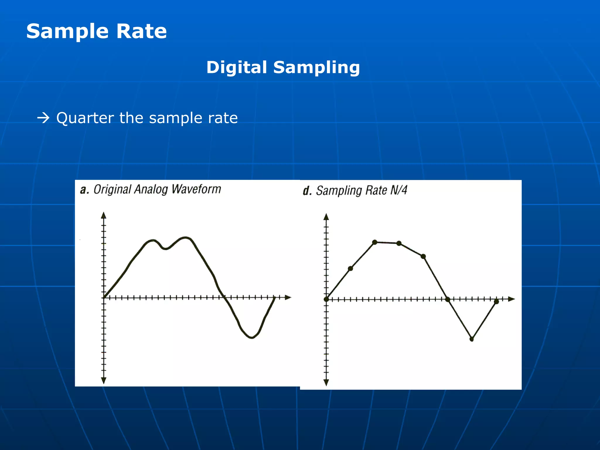
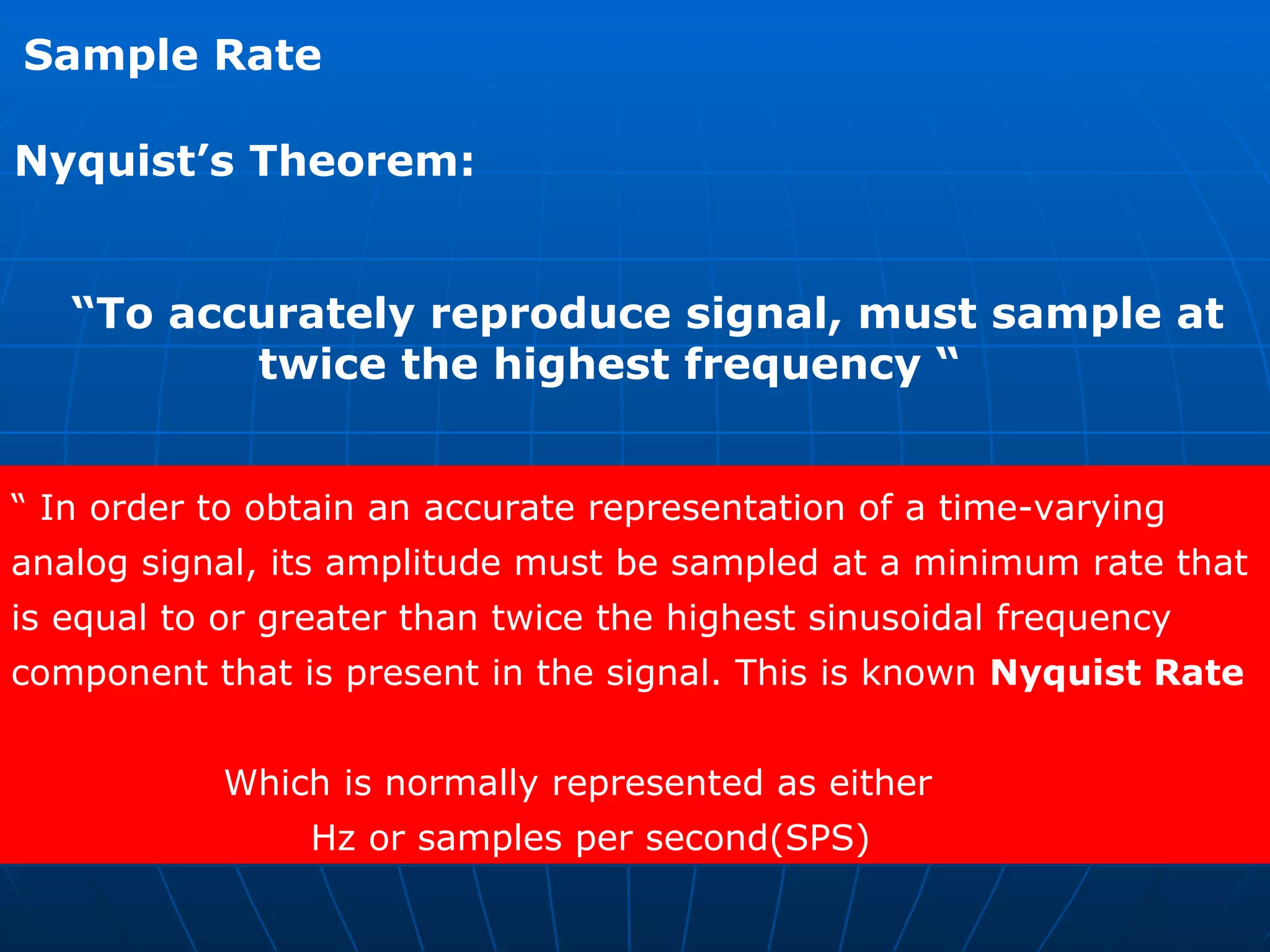
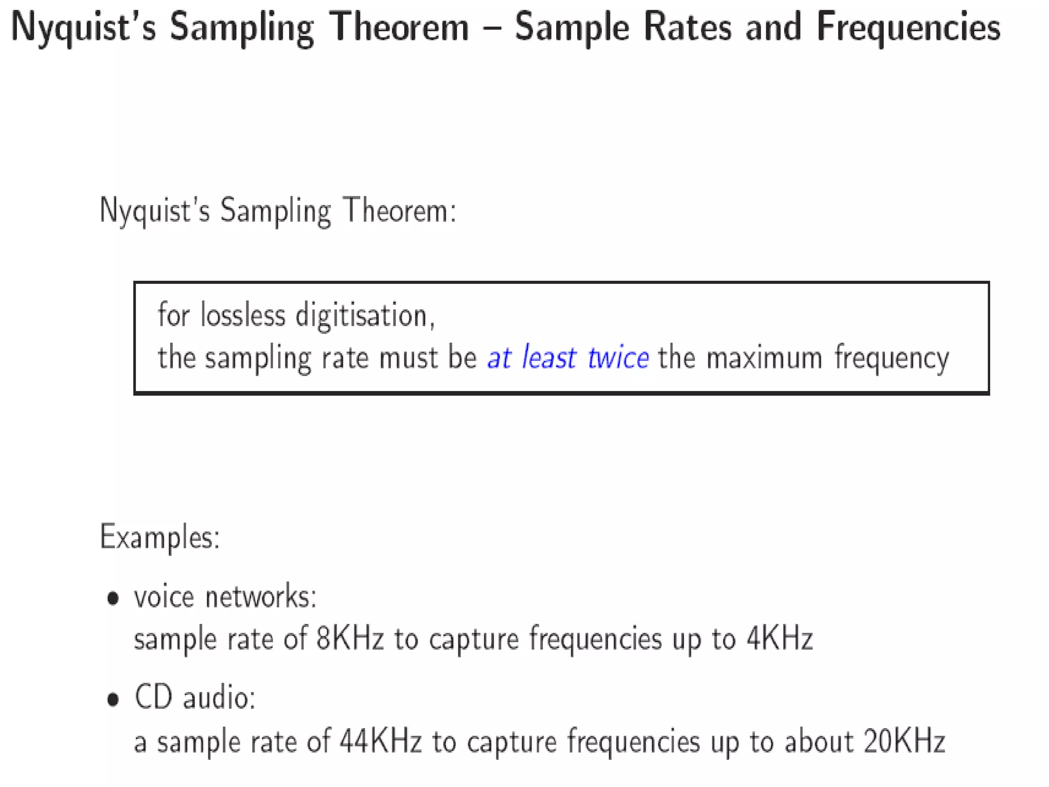
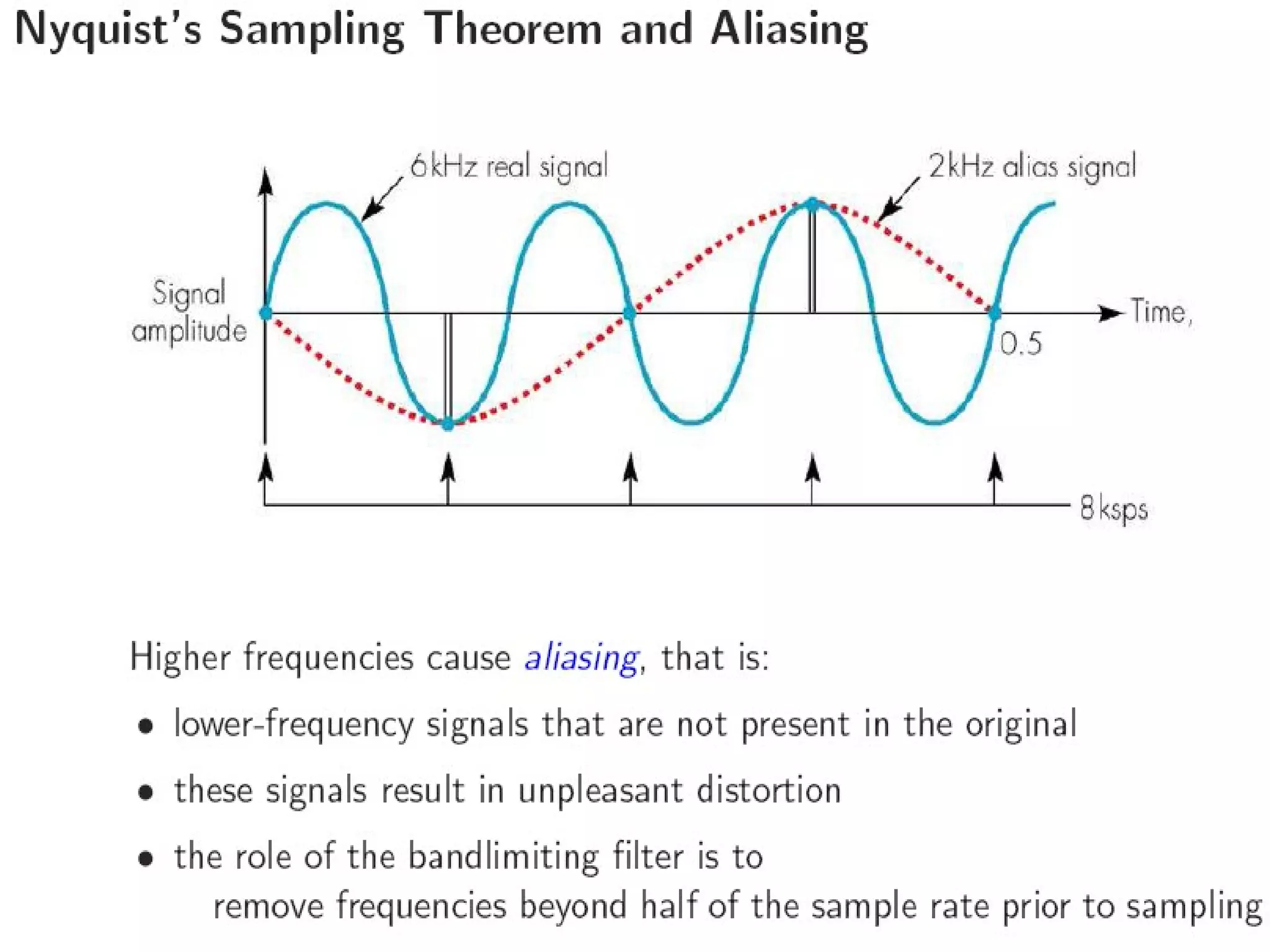
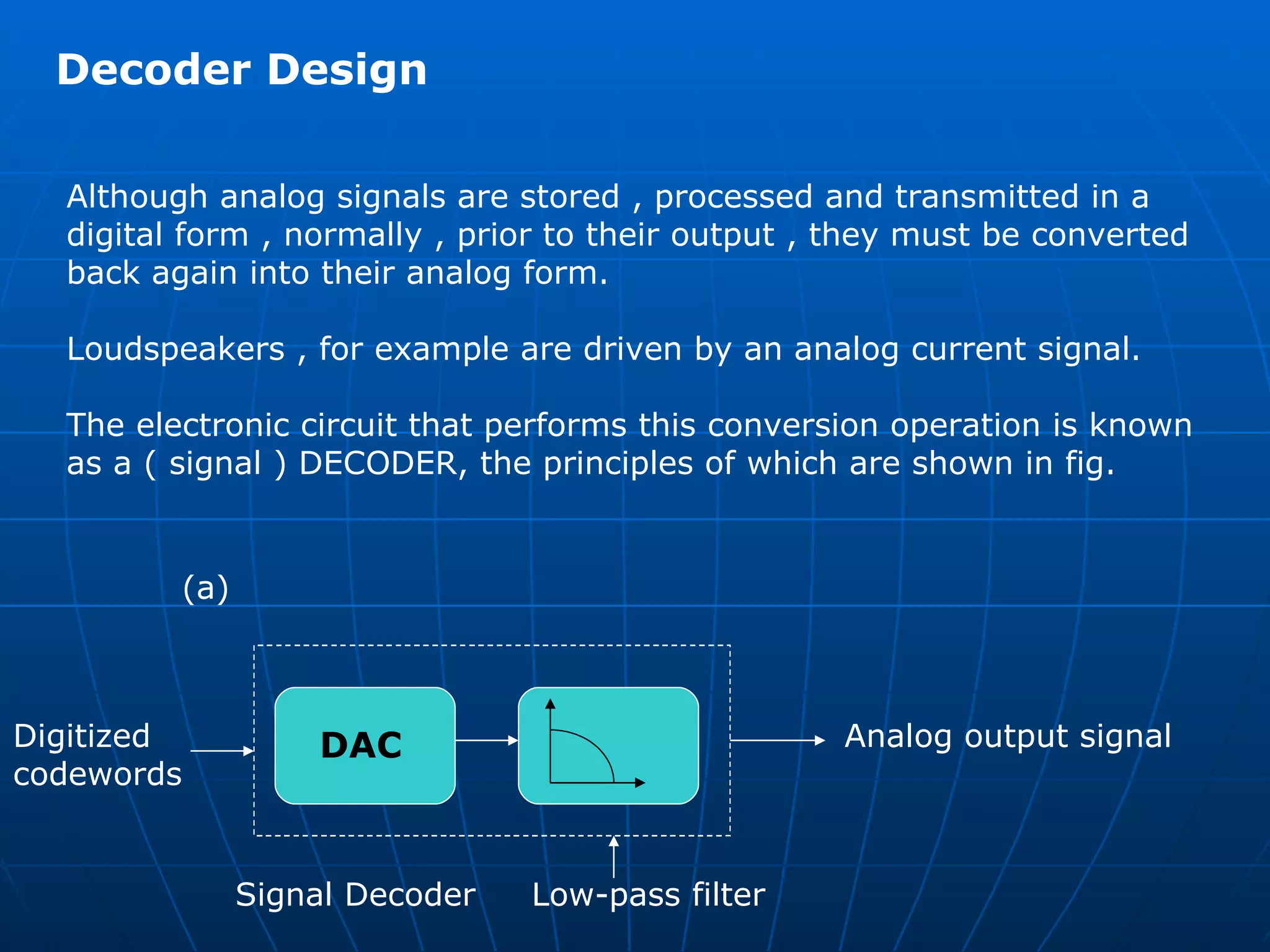
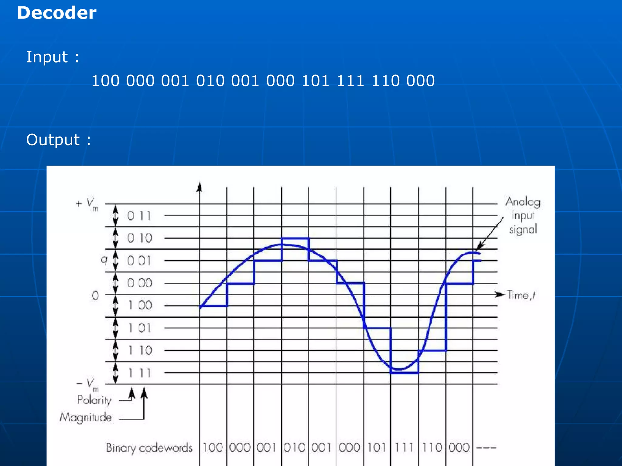
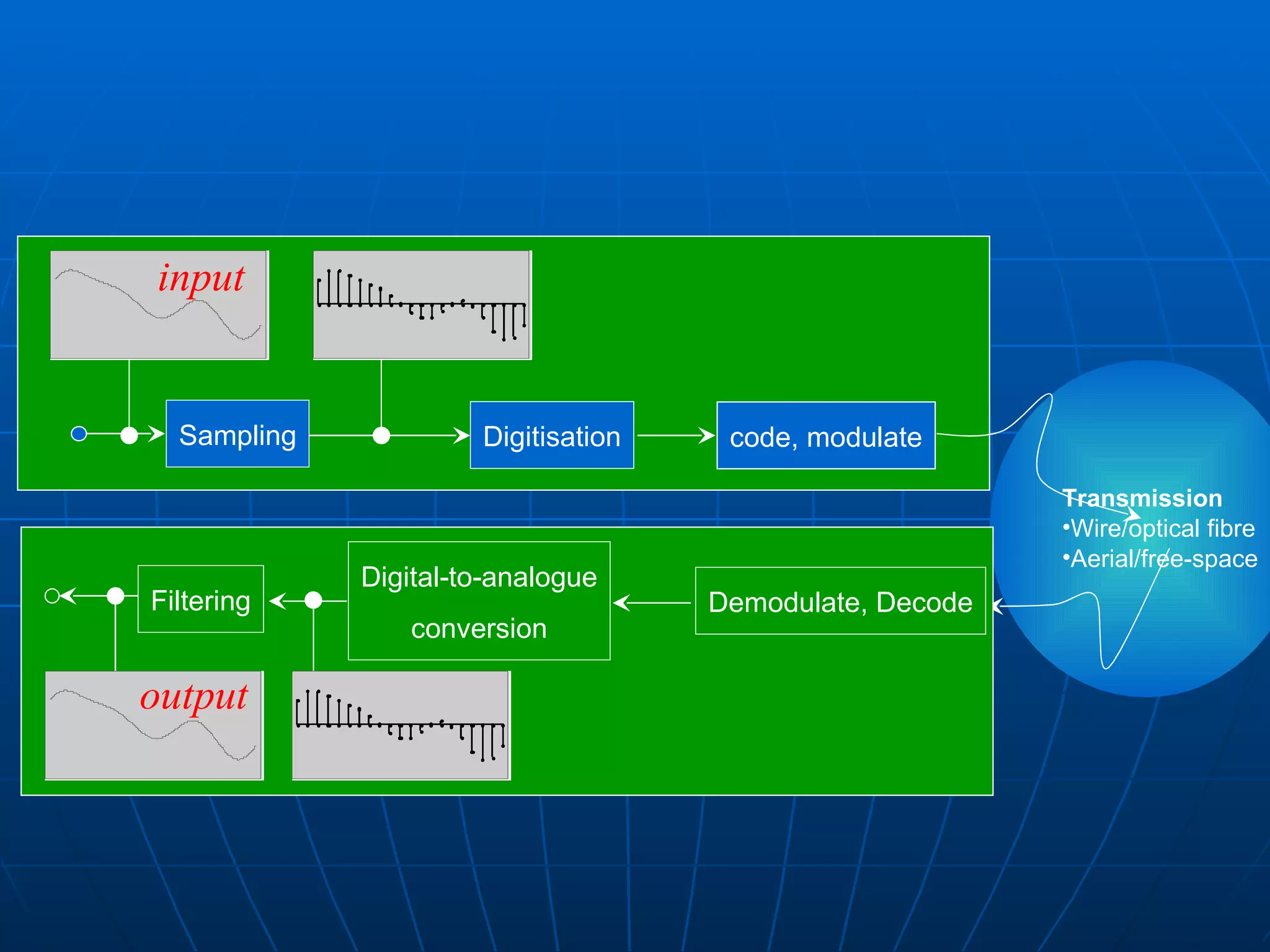
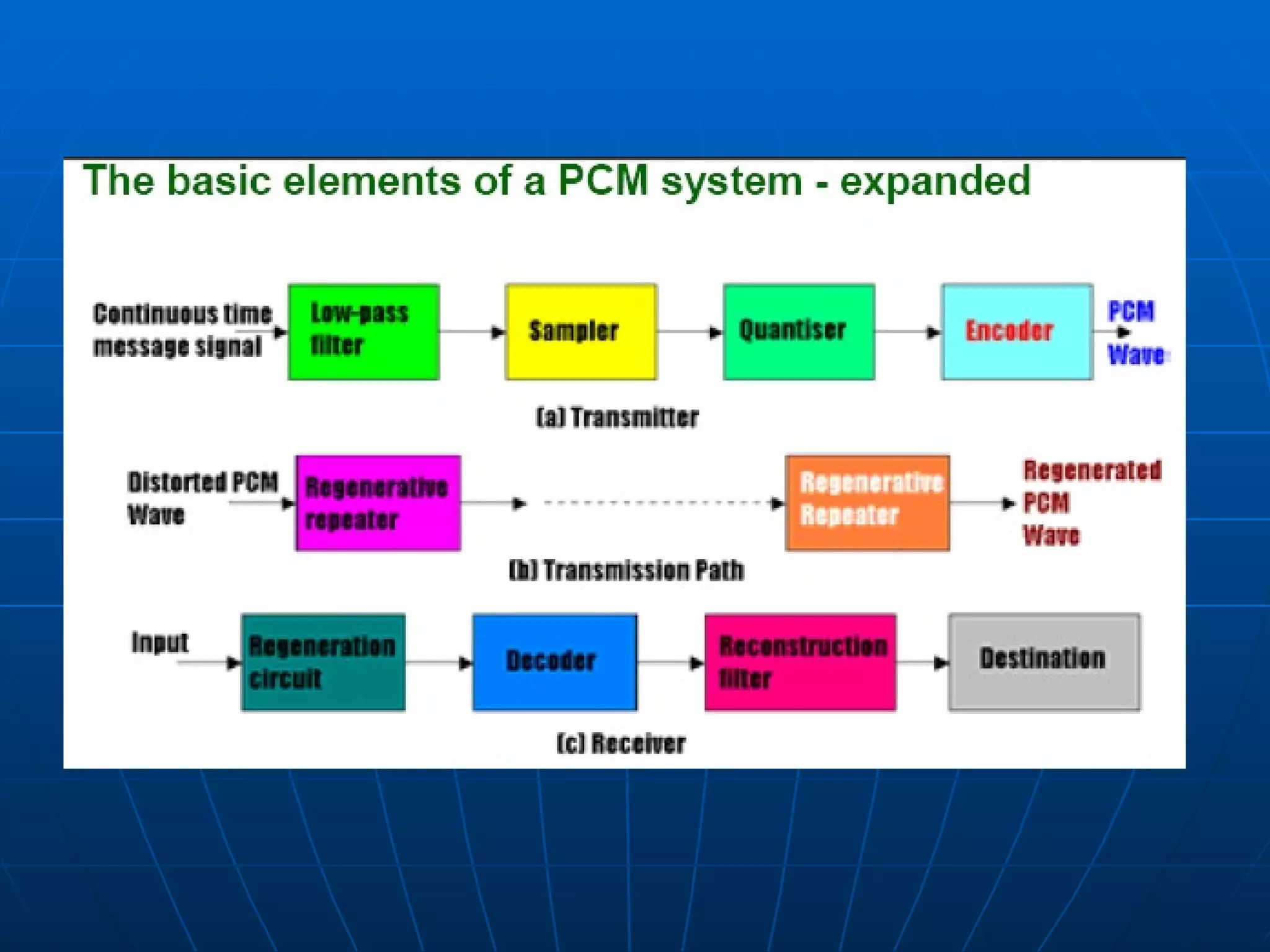
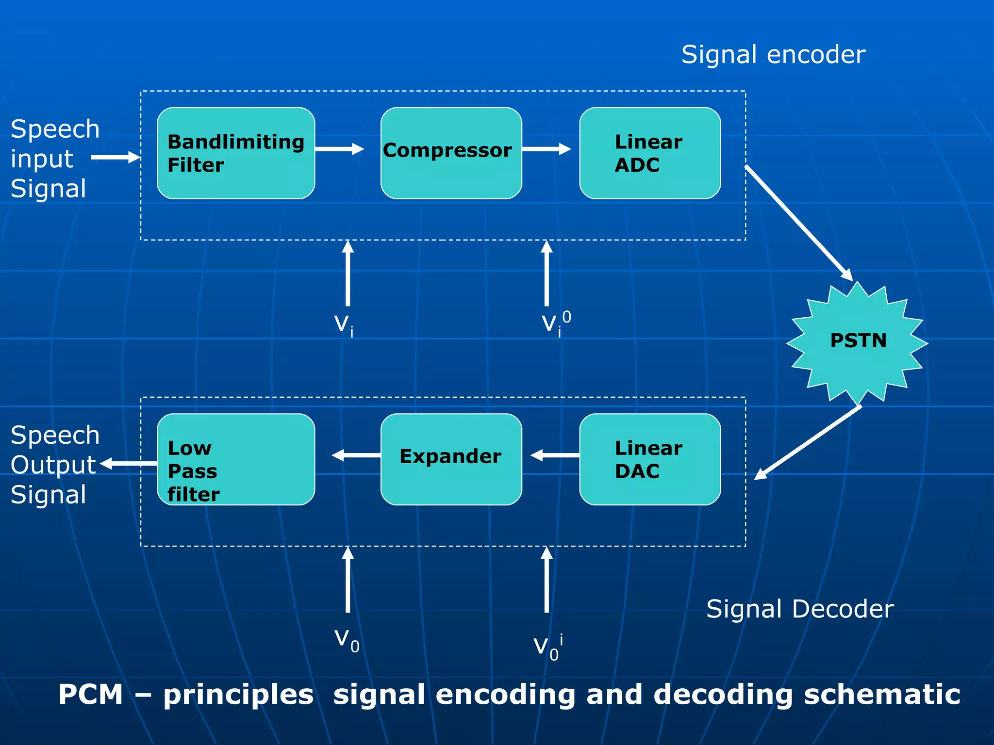
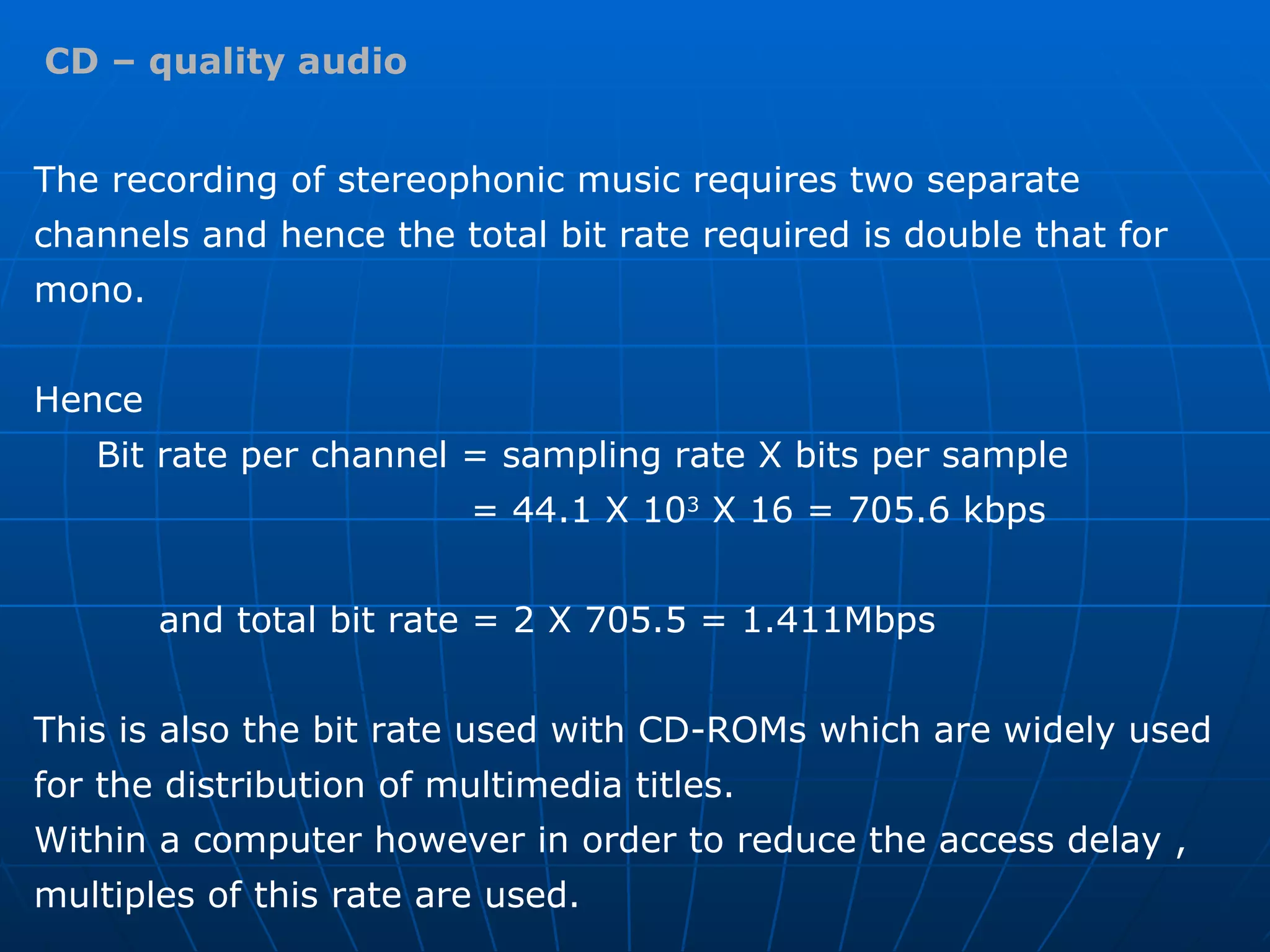
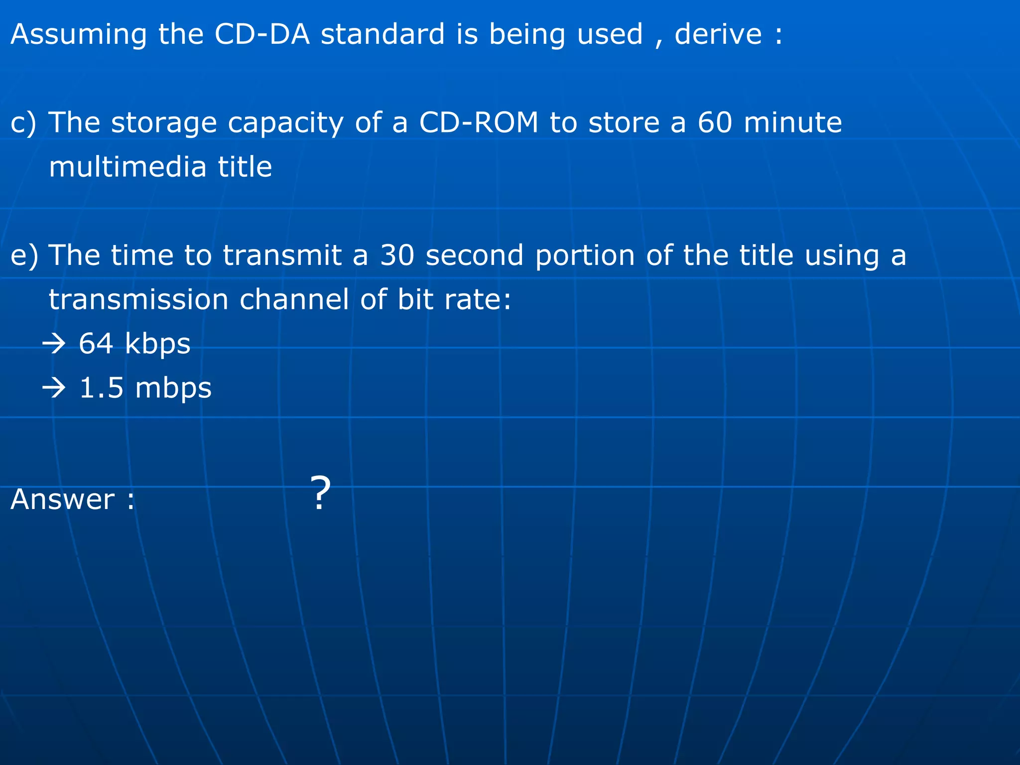
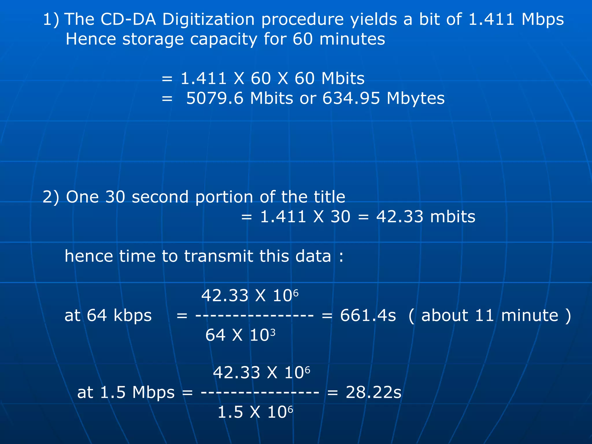
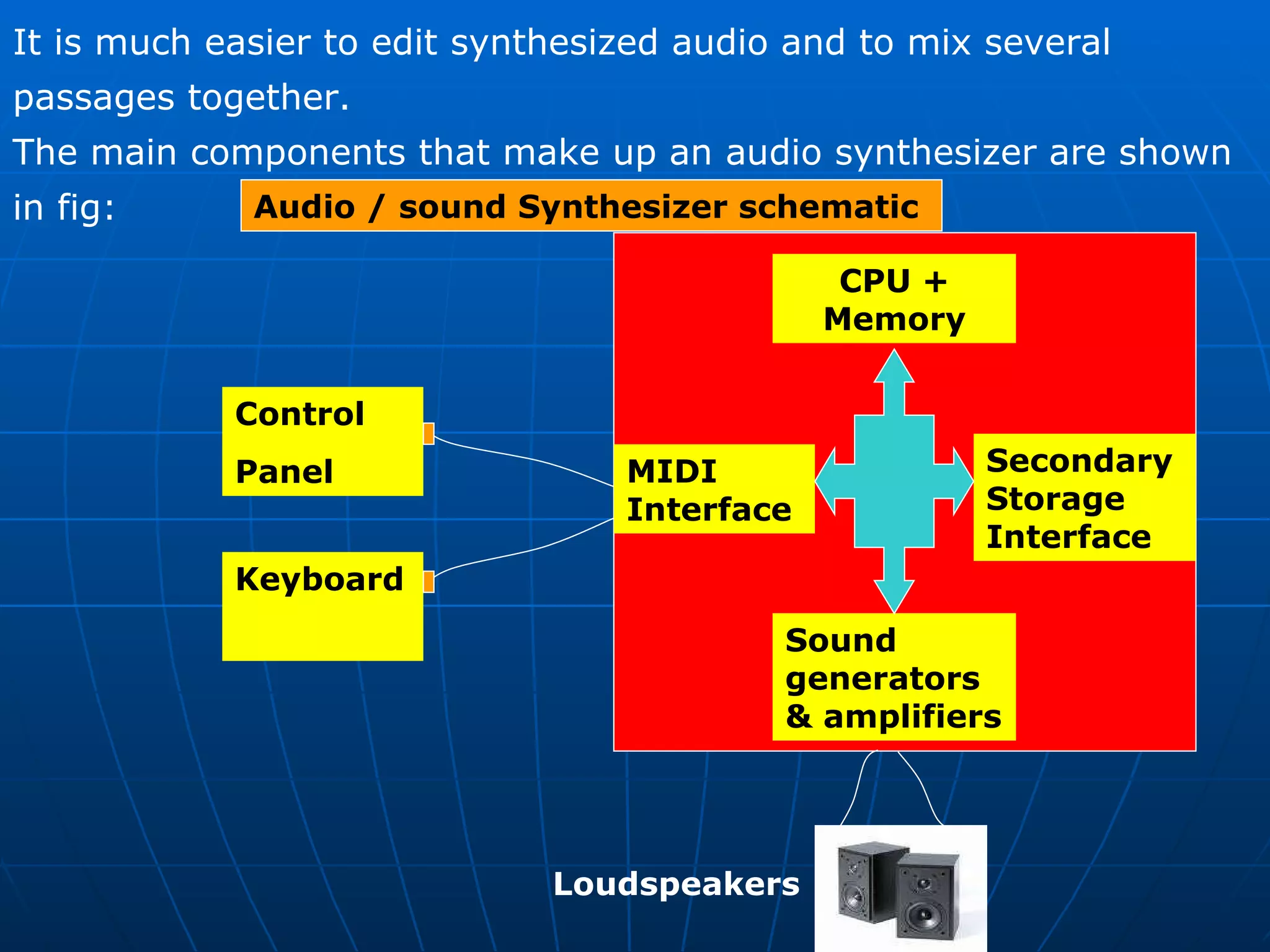
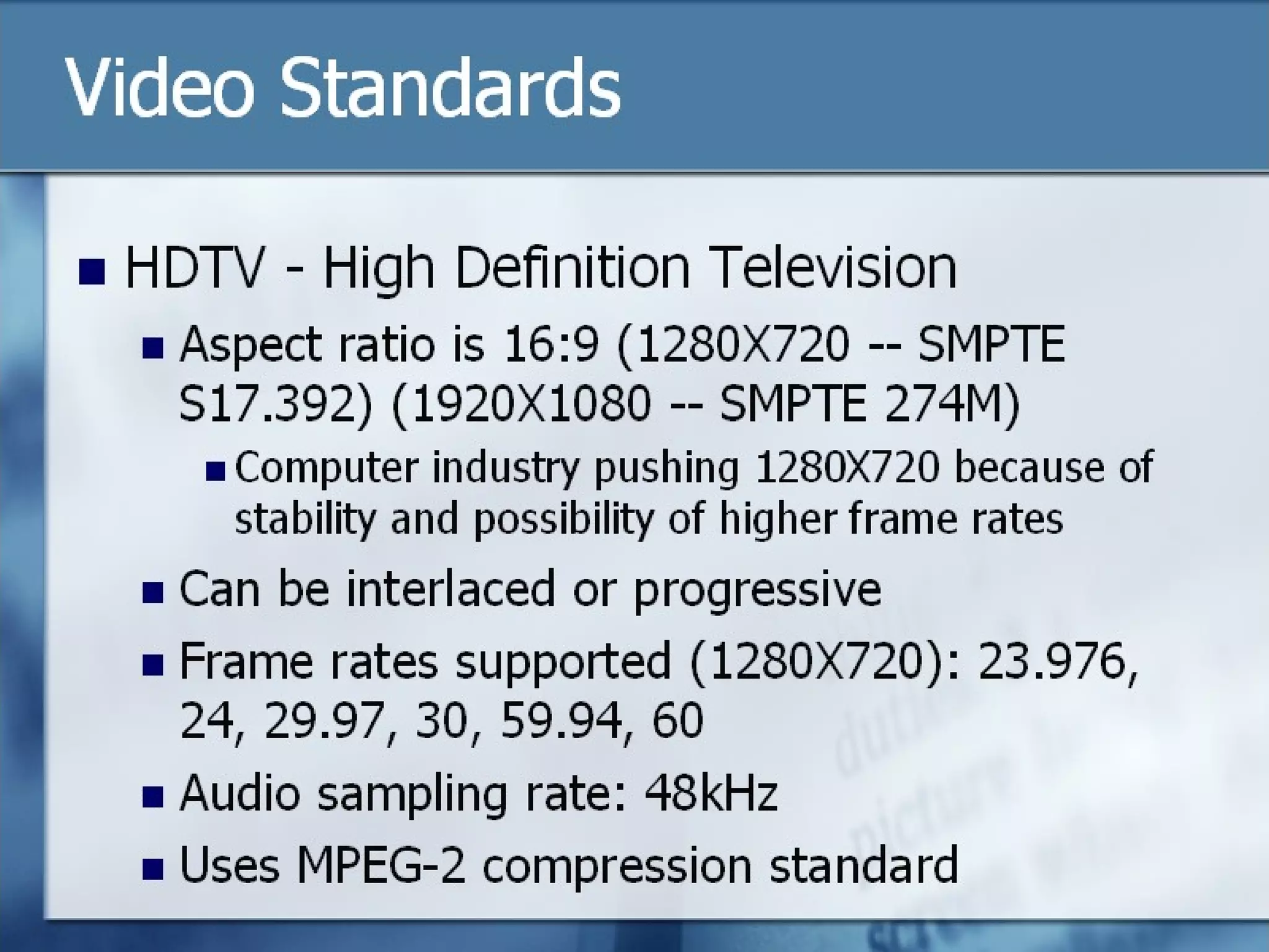
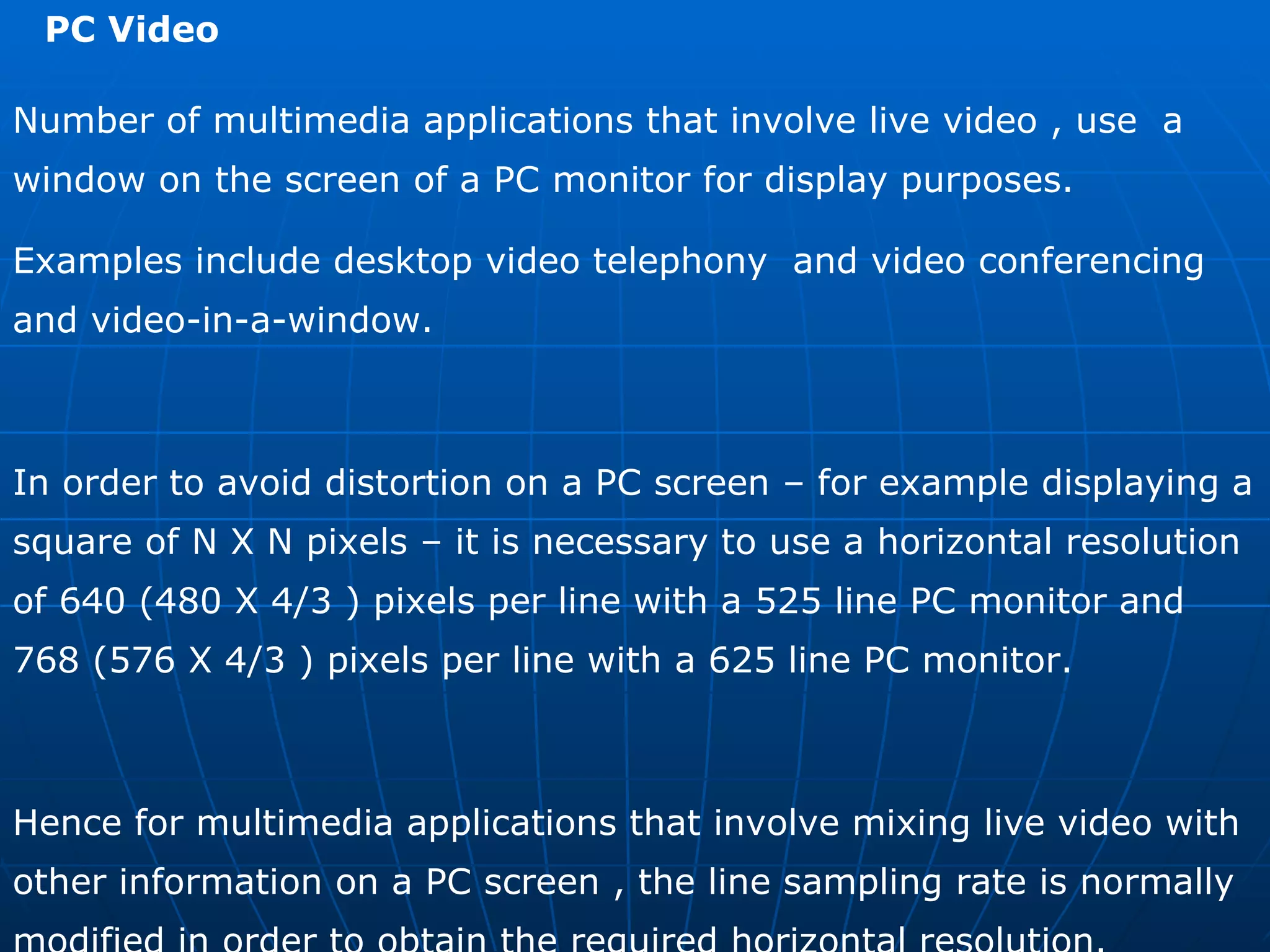
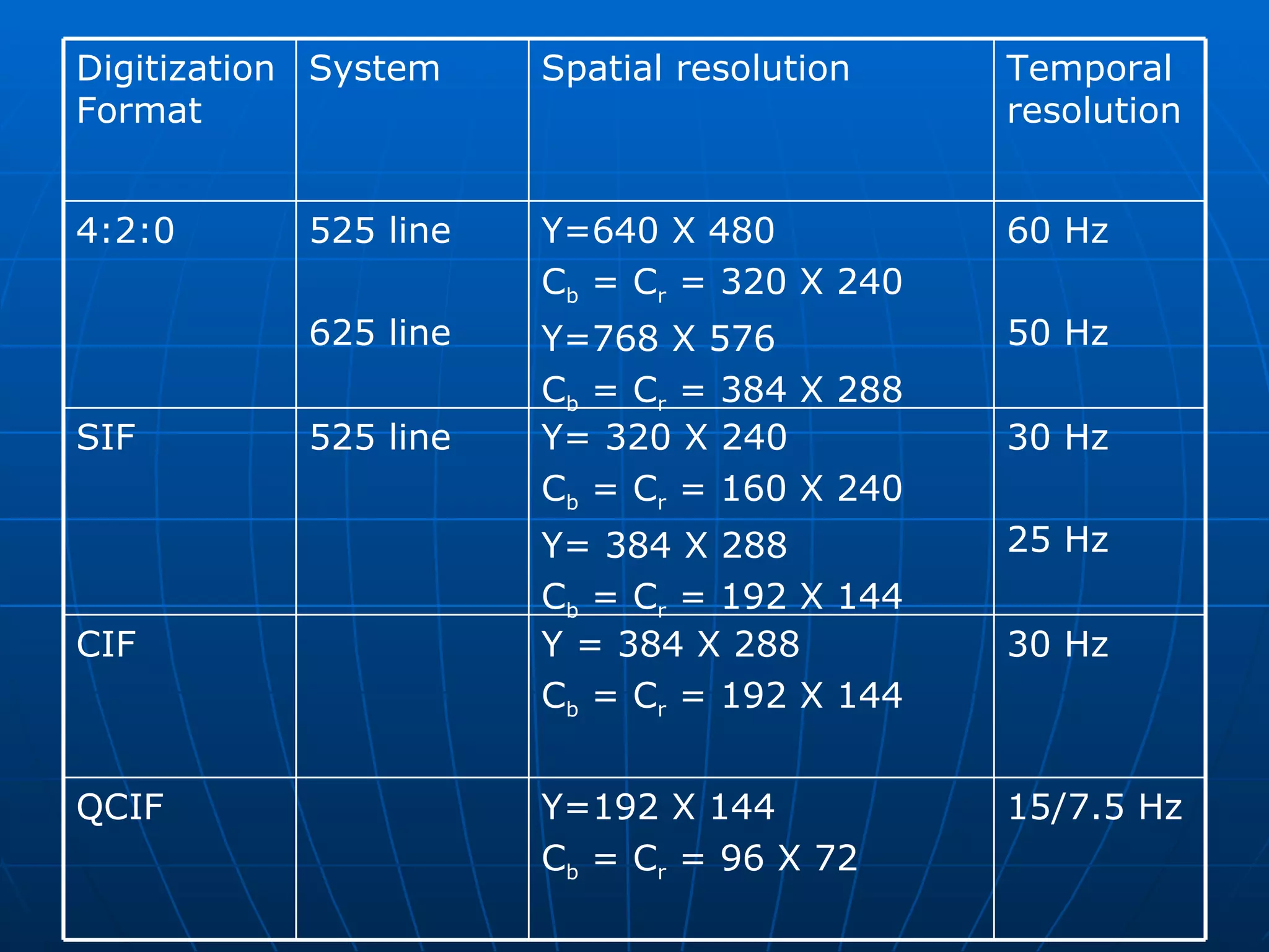
MULTIMEDIA COMPUTING  Subject Code : BCA 642A Faculty : Vinay . M Email : vinay.m@christuniversity.in Chapter 1 Multimedia Information Representation
Introduction Multimedia Communications embraces a range of applications and networking Infrastructures.  The term multimedia is used to indicate that the information / data relating  to an application may be composed of a number of different types of media  which are integrated together in some way. The different media types are text, images, speech , audio and video and  some example applications are  Video telephony (speech and video),  Multimedia electronic mail (text , audio and  video),  Electronic commerce (text ,image , audio and  video) Web TV ( text , audio and Video) and many other types
Text  : this includes both unformatted text , comprising of characters from a  limited character set, and formatted text strings as used for the  structuring, access , and presentation of electronic documents. Images   : these include computer-generated images , comprising lines ,  curves, circles and digitized images of documents and pictures. Audio  : this includes both low-fidelity speech, as used in telephony , and  high-fidelity stereophonic music as used with compact discs. Video   : this includes  short sequences of moving images ( also known as  video clips ) and complete movies, films.
The Application may involve either    person-to-person communication or    Person-to-system communication.  In general two people communicate with each other through suitable  terminal equipment (TE)  while a person interacts with a system using  either a multimedia  personal computer (PC) or workstation.     Telephone networks Data networks Broadcast television networks  Integrated services digital networks  Broadband multi-service networks There are five basic types of communication network that are used  to provide multimedia communication services :
Multimedia Applications Interpersonal Communications  conferencing call  audio bridge  Interactive application over the internet  telephone over internet VOIP  IPTV  Video conferencing  facsimile  Voice Mail  interaction with websites  Voice SMS  Entertainment applications  Movie / video on demand  Interactive TV  Games  Special effects  Animation
All types of multimedia information are stored and processed within a  computer in a digital form. In case of textual information consisting of strings of characters entered  at a keyboard , (each character is represented by a unique combination  of a fixed number of bits – known as a codeword) and hence the complete  text by a string of such codewords.  Similarly computer generated graphical images are made up of a mix of  lines, circles, squares and so on , each represented in a digital form.  A line for example is represented by means of the start and end coordinators  of the line relative to the complete image, each coordinate being defined in  the form of a pair of digital values.
Digital  Audio Sound produced by variations in air pressure Can take any continuous value Analog  component  Computers work with  digital Must convert analog to digital Use  sampling  to get discrete values
Devices such as microphones and many video camera produce electrical  signals whose amplitude varies continuously with time, the amplitude of the  signal at any point in time indicating the magnitude of the  sound-wave/image-intensity at that instant. A signal whose amplitude varies continuously with time is known as an analog signal In order to store and process such signals , it is necessary first to convert any  time–varying analog signal into a digital form. The conversion of an analog signal into a digital form is carried out using an electrical circuit known as  signal encoder . Similarly the conversion of the stored digitized samples relating to a particular media type into their corresponding time-varying analog form is preformed by an electrical circuit known as a  signal decoder .
Digitization Principles  Analog signal   Time varying analog signal  sinusoidal frequency components  a) b)
The general properties relating to any time varying analog signal are shown  in previous slides. The amplitude of such signals varies continuously with time.  In addition, a mathematical technique known as  Fourier analysis  , can be  used to show that any time varying analog signal is made up of a possibly  infinite number of single-frequency sinusoidal signals whose amplitude and  phase vary continuously with time relates to each other.  Amplitude : the maximum displacement of a periodic wave
The range of frequencies of the sinusoidal components that make up a signal  is called  SIGNAL BANDWIDTH  and two examples are shown in next slide.  These relate to an audio signal , the first  a speech signal and the second a  music signal produced by an orchestra.  In terms of speech humans produce sounds – which are converted into  electrical signals  by a microphone- that made up a range of sinusoidal signals  varying in frequency between 50 Hz and 10 kHz.  In case of music signal , however the range of signals is wider and varies  Between 15Hz and 20 kHz ( this is being comparable with the limits of  sensitivity of the ear).
 
Signal Bandwidth Effect of a limited bandwidth transmission channel
Ideally when an analog signal is being transmitted through a network  the bandwidth of the transmission channel – that is the range of  frequencies the channel will pass – should be equal to or grater than the  bandwidth of the signal .  If the bandwidth of the channel is less than this, then some of the low  And / or  high frequencies components will be lost thereby degrading the  quality of the received signal. This type of transmission channel is called a  band limiting channel  and its  effect is shown in previous slides
Encoder Design  The conversion of a time-varying analog signal of which an audio signal  into digital form is carried out using an electronic circuit known as  (signal) ENCODER . The principle of an encoder are shown in previous slide.  It consist of two main circuits  Bandlimiting filter and an Analog –to – digital converter  (ADC) The latter comprising a sample and hold and a quantizer.
A typical waveform set for a signal encoder is shown in next slide
The role of the Bandlimiting filter is to remove selected higher  frequency components from the source signal (A)  The output of the filter (B) is then fed to the sample-and-hold circuit  which , as its name implies , is used to sample the amplitude of the  filtered signal at regular time intervals (c) and to hold the sample  amplitude constant between samples (d).  This in turn , is fed to the quantizer circuit which converts each sample  amplitude into a binary value known as a codeword (E)
The most significant bit of each codeword indicates the polarity (sign) of the  sample, positive or negative relative to the zero level.  Normally binary 0 indicates a positive value and a binary 1 indicates a  negative value.
Sample Rate    Sample rate  determines number of discrete values Digital Sampling
   Half the sample rate Sample Rate Digital Sampling
   Quarter the sample rate Sample Rate Digital Sampling
Nyquist’s Theorem: “ To accurately reproduce signal, must sample at  twice the highest frequency “ Sample Rate “  In order to obtain an accurate representation of a time-varying  analog signal, its amplitude must be sampled at a minimum rate that  is equal to or greater than twice the highest sinusoidal frequency  component that is present in the signal. This is known  Nyquist Rate   Which is normally represented as either Hz or samples per second(SPS)
 
 
In the example the original signal is assumed to be a 6 kHz  sinewave which is sampled at a rate of 8ksps. Clearly this is  lower than the Nyquist rate of 12 ksps (2 X 6 kHz)  and as we can see the results in a lower-frequency 2 kHz signal  being created in place of the original 6 kHz signal.  Because of this such, signals are called alias signal since they  replace the corresponding original signals.
 
Samples have discrete values How many possible values?  -  Sample Size - Common is 256 values from 8 bits
Why not always use high sampling rate? Requires more storage Complexity and cost of analog to digital  hardware    Typically want an  adequate  sampling rate    Quantization error  from rounding Ex: 28.3 rounded to 28
Decoder Design  Although analog signals are stored , processed and transmitted in a  digital form , normally , prior to their output , they must be converted  back again into their analog form. Loudspeakers , for example are driven by an analog current signal.  The electronic circuit that performs this conversion operation is known  as a ( signal ) DECODER, the principles of which are shown in fig. DAC Digitized  codewords Analog output signal Signal Decoder  Low-pass filter (a)
Decoder  Input :  100 000 001 010 001 000 101 111 110 000  Output :
Each digital codeword is converted into an equivalent analog sample using  a circuit called a  digital-to-analog converter or DAC . This produces a signal shown in the previous slide , the amplitude of the  each level is being determined by the corresponding codeword.  Since this is a time varying signal , as indicated earlier.  ** Since in most multimedia applications involving audio and video  the communications channel is two way simultaneous,  the terminal  Equipment must support both input and output simultaneously. Hence the Audio and Video signal encoders and decoders in each terminal equipment are often combined into a single unit called an  audio/video encoder-decoder  or simply  audio/video codec.
TEXT  Essentially , there are three types of text that are used to produce  Pages of documents. Unformatted text  : This is also known as PLAINTEXT and enables pages to  be created which comprise strings of fixed sized  characters from a limited character set.  Formatted text  :  this is also known as RICHTEXT and enables pages and  complete documents to be created which comprise of  strings of characters of different styles , size, and shape with  tables , graphics, and images inserted at appropriate points Hypertext  : this enables an integrated set of documents  (each comprising formatted text ) to be created which have  defined linkages between them.
Unformatted Text ASCII code Table
 
Previous slides shows the character that are available in ASCII  Character set . The term ASCII being an observation for the  American Standard  Code for Information Interchange. This is one of the most widely used character sets and the table  includes the binary codewords used to represent each character.  Each bit is represented by a unique 7-bit binary codeword.  The use of 7 bits means that there are 128 (2 7 ) alternative characters and the codeword used to identify each character is obtained by  Combining the corresponding column (bits 7-5)  and rows (bits 4-1)  bits together.  Bit 7 is the most significant bit and hence the codeword for uppercase M , for example 1001101.
In addition to all the normal alphabetic , numeric and punctuation  characters – collectively referred to as printable characters – the  total ASCII character set also includes a number of control characters. These includes :     Format control Characters  : BS( back space) , LF (linefeed) , CR (carriage return) , SP (space) , DEL (delete), ESC (escape) and FF (form feed) Information separators  : FS (file separator) and  RS (record separator) Transmission control Characters  : SOH (Start-of-heading), STX (start-of-text) , ETX (end-of-text) , ACK (acknowledge), NAK (negative acknowledge), SYN (synchronous idle) , and DLE (data link escape)
Formatted text  An example of formatted text is that produced by most word  processing packages.  It is also used extensively in the publishing sector for the preparation of papers , books , magazines, journals and so on .  It enables the documents to be created that consists of characters of  different styles and of variable size and shape , each of which can be  plain , bold, or italicized.  In addition , a variety of document formatting options are supported  to enable an author to structure a document into chapters, sections  and paragraphs, each with different headings and with tables, graphics and pictures inserted at appropriate points.
Formatted text  formatted text  This is an example  italics  ,  BOLD  ,  underline  Font style  ,  F o n t   s i z e  Printable Version of the string Formatted text string
Hyper Text  Hyper text is a type of formatted text that enables a related set of documents – normally referred to as  pages  – to be created which have defined linkage points- referred to as  hyperlinks   - between each other.  For example most universities describe their structure and the courses and support services they offer, in a booklet known as prospectus. Like most such booklets this is organized in a hierarchical way. Hypertext can be used to create an electronic version of such documents with index , descriptions of departments, courses on offer , library and other  facilities are written in hypertext as pages  With various defined hyperlinks between them to enable a person to browse through its contents in a user friendly way.
IMAGES  Images , Graphics , Computer Graphics  All three types of image are displayed ( and printed ) in the form of a two dimensional matrix of individual picture elements – known as  pixels  or some time  pels - each type is represented differently within the computer memory or more generally in a computer file.  And also each type of image is created differently and hence it is helpful for us to consider each separately.
Graphics  There is a range of software packages and programs available for the creation of computer graphics. These provide easy-to-use tools to create graphics that are computer graphics.  These provide easy-to-use tools to create graphics that are composed of all kinds of visual objects including lines, arcs , squares, rectangles, circles, ovals, diamonds, stars  and so on , as well as any hand drawn ( freeform ) objects.
A computer’s display screen can be considered as being made of a two-dimensional matrix of individual picture elements – pixels – each of which can have a range of colors associated with it.  For example VGA ( video graphics array )  is a common type of display and , so we show in fig , consists of a matrix of 640 horizontal pixels by 480 vertical pixels with, for example 8 bits per pixel which allows each pixel to have one of 256 different colors. x=640 pixels Y=480 pixels Pixel position (x,y)
Each object has a number of attributes associated with it. These include its shape – a line , a circle, a square and so on – its size in terms of the pixel positions of its border co-ordinates, the color of the border , its shadow and so on.  An object shape is said to be either open or closed .  In case of open object , the start of the first line and end of the last line that make up the object’s border are not connected . That is they do not start and end on the same pixel.  On the other hand with the closed objects they are connected.
In case of closed objects , the pixels enclosed by its border can all be assigned the same color – known as  COLOR FILL   to create sold objects .  This operation  is also known as  RENDERING.
There are two forms of representation of a computer graphics :    a high level version  ( similar to the source code of a high-level program)  Actual pixel image of the graphic  ( similar to the byte-string corresponding to the low-level machine code of the program , more generally known as BITMAP FORMAT )  Many formats are available in which the images are stored in high level graphics  TIFF, TGA , PSD ,  Low level  Bitmap , GIF ,  JPEG ,
Digitized Documents  An example of a digitized documents is that produced by the scanner associated with a facsimile ( fax ) machine, the principles of which is shown below. Page being  scanned Scanning head  Network Printed digital Image The scanner associated with a fax machine operates by scanning  each complete page from left to right to produce a sequence of scan  lines that start at the top of the page and end at the bottom.
The vertical resolution of the scanning procedure is either 3.85 or 7.7 lines per millimeter which is equivalent to approximately 100 or 200 lines per inch.  As each line is scanned the output of the scanner is digitized to a resolution of approximately 8 picture elements.- known as pels with fax machine – per millimeter. Fax machine use just a single binary digit to represent each pel, a 0 for a white pel and a 1 for a black pel.
For a typical page , produces a stream of about two million bits.  The printer part of a fax machine then reproduces the original image by printing out the received stream of bits to a similar resolution. In general the use of a single binary digit per pel means that fax  machines are best suited to scanning bitonal ( black and white )  images such as printed documents comprising mainly textual  information
Digitized pictures  In case of scanners which are used for digitizing continuous-tone  Monochromatic images such as a printed picture or scene – normally  more than a single bit is used  to digitize each picture element.  For Ex : Good quality black and white pictures can be obtained by using 8 bits  per picture element. This yields 256 different levels of gray per  element – varying between white and black which gives a  substantially improved picture quality over a facsimile image when  reproduced.
In case of color images , in order to understand the digitization format used , it is necessary first to obtain an understanding of  the principles of how color is produced and how the picture tube  Used in computer monitors ( on which the images are eventually  displayed ) operate. COLOR PRINCIPLES  Human eye sees just a single color when a particular set of three  Primary colors are mixed and displayed simultaneously . In fact a whole spectrum of colors known as a color gamut can be  produced by using different proportions of the three primary colors RED (R) GREEN (G) BLUE (B) .
Color Derivation Principles a) Additive color Mixing  The mixing technique used in part (A) is known as Additive Color  Mixing which , since black is produced when all three primary colors  are zero, is particularly useful for producing a color image on a black  surface as in the case of display applications.
It is also possible to perform the complimentary subtractive color  mixing operation to produce a similar range of colors.  This is shown in the figure and , as we can see , with  subtractive mixing white is produced when all three chosen primary  colors cyan (C) , magenta (M) , Yellow (Y)  all are zero .  Hence the choice of colors is particularly useful for producing a color  image on a white surface as is the case of printing Applications. b) Subtractive color Mixing
Raster Scan Principles  Raster Scan Display Architecture  Refer V SEM  Computer Graphics
Pixel depth   The number of bits per pixel is known as the pixel depth and  determines range of colors that can be produced .  For example  12 bits – 4 bits per primary color yielding 4096 different colors  24 bits – 8 bites per primary color yielding in excess of 16 million (2 24  )
Aspect Ratio  Both the number of pixels per scanned line and the number of lines  per frame vary , the actual numbers used being determined by what  is known as the ASPECT RATIO of the display screen. This is the screen width to screen height.  NTSC (US ) , PAL (EUROPE )  , CCIR (GERMANY) , SECAM (FRANCE)
AUDIO  We care concerned with two types of audio signal  Speech signals as used in a variety of interpersonal applications including telephony and video telephony.  Music quality audio as used in applications such as CD-on Demand  and broadcast television.  In general audio can be produced either naturally by means of  microphone or electrically using some form of synthesizer .  In the case of synthesizer the audio is created in a digital form and hence can be stored within the computer memory.
We discussed the general principles behind the design of a signal  encoder and decoder earlier in the previous slides.  Here we will simply apply these principles to explain the digitization  of both speech and music produced by a microphone. The bandwidth of a typical speech signal is from 50 Hz through  to 10 kHz and that of a music signal from 15 Hz through to 20 kHz. Hence the sampling rate used for two signals must be in excess of  their  Nyquist rate which is 20Ksps (2X10kHz) for speech  and 40ksps ( 2 X 20 kHz) for music.
Q ? Assuming the bandwidth of a speech signal is from 50 Hz through  to 10 kHz and that of a music signal is from 15 Hz through to  20 kHz, derive the bit rate that is generated by the digitization  procedure in each case assuming the Nyquist sampling rate is used  with 12 bits per sample for the music signal.  Derive the memory required to store a 10 minute passage of  stereophonic music. Answer : i) Bit rates : Nyquist sampling rate = 2 f max   Speech : Nyquist rate = 2 X 10 kHz = 20kHz or 20ksps hence with 12 bits per sample , bit rate generated  = 20 k x 12 = 240 kbps  Music = Nyquist rate = 2 X 20 kHz = 40 KHz or 40 ksps hence bit rate generated = 40 k X 16 = 640kbps (mono) or 2 X 640 K = 1280 kbps (stereo)
II ) memory required  Memory required = bitrate (bps) X time (s) / 8 bytes  hence at 1280 kbps and 600s 1280 X 10 3  X 600  memory required : ------------------------  :  96 MB  8
Sampling Digitisation code, modulate Transmission Wire/optical fibre Aerial/free-space input Filtering Digital-to-analogue conversion Demodulate, Decode output
Historically source signals (voice and video) were in analogue format, however, more recently, digital video sources have become available. •  To digitally transmit analogue source signals, the signal has to  be transformed via an analogue to digital conversion. •  Three important methods of analogue to digital conversion are: –  pulse-code modulation –  differential pulse-code modulation –  delta modulation
The first operation performed in the conversion of an analogue signal into digital form involves the representation of the signal by a sequence of uniformly spaced pulses, the amplitude of which is modulated by the signal. In both pulse-code modulation and differential pulse-code modulation, the pulse repetition frequency, or the sampling rate is chosen to be slightly greater than the Nyquist rate (i.e.  greater than twice the highest frequency component ) of the analogue signal.
 
In  delta modulation , the sampling rate is chosen to be much greater than the Nyquist rate. The reason for this is to increase correlation between adjacent samples derived from the information-bearing analogue signal and thereby to simplify the physical implementation of the delta modulation process. •  The distinguishing feature between pulse-code modulation and differential pulse-code modulation is that in the latter case, additional circuitry (designed to perform linear prediction) is used to exploit the correlation between adjacent samples of the analogue signal so as to reduce the transmitted bit rate. •  Pulse-code modulation is viewed as a benchmark against which other methods of digital pulse modulation are measured in performance and circuit complexity.
PCM was developed in 1937 at the Paris Laboratories of AT&T. Alex H. Reeves was the inventor. •  Reeves conducted several successful transmission experiments across the English Channel using various modulation techniques, including pulse-width modulation (PWM), pulseamplitude modulation (PAM) and pulse-pulse modulation (PPM). •  Circuitry was quite complex and expensive in the early stages of development. •  In the 1960s, the evolution of the semiconductor industry permitted low cost circuits to be fabricated. PCM became the preferred method of transmitting over the PSTN.
PCM is a method of serially transmitting an approximate representation of an analogue signal. •  The PCM is itself a succession of discrete numerically encoded binary values derived from digitizing the analogue signal. •  The maximum expected amplitude of the analogue signal is quantized . That is, divided into discrete numerical levels. The number of discrete levels depends on the resolution (number of bits) of the analogue-to-digital (A/D) converter used to digitize the signal. •  If an 8-bit A/D converter is used, the analogue signal is quantized into 256 (28) discrete levels. •  quantizing range = 2(no. of A/D converter bits)
The essential operations in the transmitter of a PCM system are sampling, quantising, and encoding. •  The quantising and encoding operations are usually performed in the same circuit, which is called an analogue-to-digital converter. •  The essential operations in the receiver are regeneration of impaired signals, decoding and demodulation of the train of quantised samples. •  These operations are usually performed in the same circuit, which is called a digital-to-analogue converter. •  At intermediate points along the transmission route from the transmitter to the receiver, regenerative repeaters are used to reconstruct (regenerate) the transmitted sequence of coded pulses to reduce the effects of signal distortion and noise.
 
 
Bandlimiting Filter Speech  input  Signal  Signal Decoder  Compressor Linear  ADC PSTN Signal encoder  Low Pass filter Speech  Output Signal  Expander Linear  DAC v i v i 0 v 0 i v 0 PCM – principles  signal encoding and decoding schematic
CD – quality audio The discs used in CD players and CD-ROM are digital storage devices for stereophonic music and more general multimedia information streams. There is a standard associated with these devices which is known as the  CD digital audio  (CD_DA) standard. As indicated earlier, music has an audible bandwidth of from 15Hz through to 20kHz and hence the minimum sampling rate is 40ksps. In the standard , however the actual rate used is higher than this rate firstly to allow for imperfections in the Bandlimiting filter used and secondly, so that the resulting bit rate is then compatible with one of the higher transmission channel bit rates available with public networks.
CD – quality audio One of the sampling rates used is 44.1 ksps which means  the signal is sampled at 23 microsecond intervals.  Since the bandwidth of a recording channel on a CD is large, a high number of bits per sample can be used.  The standard defines 16 bits per sample which , as indicated earlier, tests have shown to be the minimum required with music to avoid the effect of quantization noise.  With this number of bits , linear quantization can be used which yields 65536 equal quantization intervals.
CD – quality audio The recording of stereophonic music requires two separate channels and hence the total bit rate required is double that for mono. Hence  Bit rate per channel = sampling rate X bits per sample  = 44.1 X 10 3  X 16 = 705.6 kbps and total bit rate = 2 X 705.5 = 1.411Mbps This is also the bit rate used with CD-ROMs which are widely used for the distribution of multimedia titles.  Within a computer however in order to reduce the access delay , multiples of this rate are used.
Assuming the CD-DA standard is being used , derive : The storage capacity of a CD-ROM to store a 60 minute multimedia title  The time to transmit a 30 second portion of the title using a transmission channel of bit rate:    64 kbps     1.5 mbps  Answer :  ?
The CD-DA Digitization procedure yields a bit of 1.411 Mbps Hence storage capacity for 60 minutes  = 1.411 X 60 X 60 Mbits  =  5079.6 Mbits or 634.95 Mbytes  2) One 30 second portion of the title  = 1.411 X 30 = 42.33 mbits hence time to transmit this data :   42.33 X 10 6 at 64 kbps  = ---------------- = 661.4s  ( about 11 minute ) 64 X 10 3     42.33 X 10 6   at 1.5 Mbps = ---------------- = 28.22s 1.5 X 10 6
Synthesized audio  Once digitized , any form of audio can be stored within a computer .  However as we can see from the results obtained in the next example , the amount of memory required to store a digitized audio waveform can be very large, even for relatively short passages. It is for this reason that synthesized audio is often used in multimedia applications since the amount of memory required can be between two and three orders of magnitude less than that required to store the equivalent digitized waveform version.
It is much easier to edit synthesized audio and to mix several passages together.  The main components that make up an audio synthesizer are shown in fig:  MIDI Interface Sound generators & amplifiers Control Panel  Secondary Storage Interface Keyboard Loudspeakers Audio / sound Synthesizer schematic  CPU + Memory
The three main components are the  computer  (with various application programs),  the keyboard  ( based on that of a piano)  and the set of sound generators.   Essentially the computer takes input commands from the keyboard and outputs these to the sound generators which , in turn , produce the corresponding sound waveform – via DACs – to drive the speakers. MIDI ( Musical Instrument Digital Interface )  It doesn't just define the format of the standardized  set of messages used by a synthesizer, but also the type of  connectors,  cables and electrical signals  that are used to connect any  type of device to the Synthesizer .
Video   Video features in a range of multimedia applications Entertainment broadcast television and VCR / DVD recordings Interpersonal : Video telephony and video conferencing  Interactive : windows containing short video clips
The  quality of the video required however , varies considerably from  one type of application to another. For example , for video telephony ,  a small window on the screen of a PC is acceptable while for a movie a large screen format is preferable. In practice , therefore there is not just a single standard associated  with video but rather a set of standards , each targeted at a particular  application domain.  Before describing a selection of these we must first acquire an  understanding of the basic principles associated with broadcast television on which all the standards are based.


Digital Video In most multimedia applications the video signals need to be in a digital form since it then becomes possible to store them in the memory of a computer  and to readily edit and integrate them with other media types. In addition , although for transmission reasons the three components signals have to be combined for analog television broadcasts , with digital television it is more usual to digitize the three component signals separately prior to their transmission. Again this is done to enable editing and other operations to be readily performed.
Since the three component signals are treated separately in digital television, in principle it is possible simply to digitize the three RGB signals that make up the picture. The disadvantage of this approach is that the same resolution – in terms of sampling rate and bits per sample- must be used for all three signals.  Studies on the visual perception of the eye have shown that the resolution of the eye is less sensitive for color than it is for luminance .
Digitization of video signals has been carried out in television for many years in order , for example to perform conversations from one video format into another. In order to standardize this process and hence make the exchange of television programs internationally easier – the international body for television standards, the International Telecommunications Union Radio communications Branch (ITU-R) – formerly known as the consultative Committee for International Radio Communications (CCIR) – defined a standard for the digitization of video pictures known as Recommendation CCIR-601.
PC Video  Number of multimedia applications that involve live video , use  a window on the screen of a PC monitor for display purposes. Examples include desktop video telephony  and video conferencing and video-in-a-window. In order to avoid distortion on a PC screen – for example displaying a square of N X N pixels – it is necessary to use a horizontal resolution of 640 (480 X 4/3 ) pixels per line with a 525 line PC monitor and 768 (576 X 4/3 ) pixels per line with a 625 line PC monitor. Hence for multimedia applications that involve mixing live video with other information on a PC screen , the line sampling rate is normally modified in order to obtain the required horizontal resolution.
15/7.5 Hz  Y=192 X 144 C b  = C r  = 96 X 72  QCIF 30 Hz Y = 384 X 288  C b  = C r  = 192 X 144 CIF 30 Hz 25 Hz Y= 320 X 240  C b  = C r  = 160 X 240  Y= 384 X 288 C b  = C r  = 192 X 144 525 line SIF  60 Hz 50 Hz Y=640 X 480 C b  = C r  = 320 X 240  Y=768 X 576 C b  = C r  = 384 X 288 525 line 625 line 4:2:0 Temporal resolution Spatial resolution  System  Digitization Format
Video Content

multimedia chapter1

  • 1.
    MULTIMEDIA COMPUTING Subject Code : BCA 642A Faculty : Vinay . M Email : vinay.m@christuniversity.in Chapter 1 Multimedia Information Representation
  • 2.
    Introduction Multimedia Communicationsembraces a range of applications and networking Infrastructures. The term multimedia is used to indicate that the information / data relating to an application may be composed of a number of different types of media which are integrated together in some way. The different media types are text, images, speech , audio and video and some example applications are Video telephony (speech and video), Multimedia electronic mail (text , audio and video), Electronic commerce (text ,image , audio and video) Web TV ( text , audio and Video) and many other types
  • 3.
    Text :this includes both unformatted text , comprising of characters from a limited character set, and formatted text strings as used for the structuring, access , and presentation of electronic documents. Images : these include computer-generated images , comprising lines , curves, circles and digitized images of documents and pictures. Audio : this includes both low-fidelity speech, as used in telephony , and high-fidelity stereophonic music as used with compact discs. Video : this includes short sequences of moving images ( also known as video clips ) and complete movies, films.
  • 4.
    The Application mayinvolve either person-to-person communication or Person-to-system communication. In general two people communicate with each other through suitable terminal equipment (TE) while a person interacts with a system using either a multimedia personal computer (PC) or workstation.  Telephone networks Data networks Broadcast television networks Integrated services digital networks Broadband multi-service networks There are five basic types of communication network that are used to provide multimedia communication services :
  • 5.
    Multimedia Applications InterpersonalCommunications conferencing call audio bridge Interactive application over the internet telephone over internet VOIP IPTV Video conferencing facsimile Voice Mail interaction with websites Voice SMS Entertainment applications Movie / video on demand Interactive TV Games Special effects Animation
  • 6.
    All types ofmultimedia information are stored and processed within a computer in a digital form. In case of textual information consisting of strings of characters entered at a keyboard , (each character is represented by a unique combination of a fixed number of bits – known as a codeword) and hence the complete text by a string of such codewords. Similarly computer generated graphical images are made up of a mix of lines, circles, squares and so on , each represented in a digital form. A line for example is represented by means of the start and end coordinators of the line relative to the complete image, each coordinate being defined in the form of a pair of digital values.
  • 7.
    Digital AudioSound produced by variations in air pressure Can take any continuous value Analog component  Computers work with digital Must convert analog to digital Use sampling to get discrete values
  • 8.
    Devices such asmicrophones and many video camera produce electrical signals whose amplitude varies continuously with time, the amplitude of the signal at any point in time indicating the magnitude of the sound-wave/image-intensity at that instant. A signal whose amplitude varies continuously with time is known as an analog signal In order to store and process such signals , it is necessary first to convert any time–varying analog signal into a digital form. The conversion of an analog signal into a digital form is carried out using an electrical circuit known as signal encoder . Similarly the conversion of the stored digitized samples relating to a particular media type into their corresponding time-varying analog form is preformed by an electrical circuit known as a signal decoder .
  • 9.
    Digitization Principles Analog signal Time varying analog signal sinusoidal frequency components a) b)
  • 10.
    The general propertiesrelating to any time varying analog signal are shown in previous slides. The amplitude of such signals varies continuously with time. In addition, a mathematical technique known as Fourier analysis , can be used to show that any time varying analog signal is made up of a possibly infinite number of single-frequency sinusoidal signals whose amplitude and phase vary continuously with time relates to each other. Amplitude : the maximum displacement of a periodic wave
  • 11.
    The range offrequencies of the sinusoidal components that make up a signal is called SIGNAL BANDWIDTH and two examples are shown in next slide. These relate to an audio signal , the first a speech signal and the second a music signal produced by an orchestra. In terms of speech humans produce sounds – which are converted into electrical signals by a microphone- that made up a range of sinusoidal signals varying in frequency between 50 Hz and 10 kHz. In case of music signal , however the range of signals is wider and varies Between 15Hz and 20 kHz ( this is being comparable with the limits of sensitivity of the ear).
  • 12.
  • 13.
    Signal Bandwidth Effectof a limited bandwidth transmission channel
  • 14.
    Ideally when ananalog signal is being transmitted through a network the bandwidth of the transmission channel – that is the range of frequencies the channel will pass – should be equal to or grater than the bandwidth of the signal . If the bandwidth of the channel is less than this, then some of the low And / or high frequencies components will be lost thereby degrading the quality of the received signal. This type of transmission channel is called a band limiting channel and its effect is shown in previous slides
  • 15.
    Encoder Design The conversion of a time-varying analog signal of which an audio signal into digital form is carried out using an electronic circuit known as (signal) ENCODER . The principle of an encoder are shown in previous slide. It consist of two main circuits Bandlimiting filter and an Analog –to – digital converter (ADC) The latter comprising a sample and hold and a quantizer.
  • 16.
    A typical waveformset for a signal encoder is shown in next slide
  • 17.
    The role ofthe Bandlimiting filter is to remove selected higher frequency components from the source signal (A) The output of the filter (B) is then fed to the sample-and-hold circuit which , as its name implies , is used to sample the amplitude of the filtered signal at regular time intervals (c) and to hold the sample amplitude constant between samples (d). This in turn , is fed to the quantizer circuit which converts each sample amplitude into a binary value known as a codeword (E)
  • 18.
    The most significantbit of each codeword indicates the polarity (sign) of the sample, positive or negative relative to the zero level. Normally binary 0 indicates a positive value and a binary 1 indicates a negative value.
  • 19.
    Sample Rate  Sample rate determines number of discrete values Digital Sampling
  • 20.
    Half the sample rate Sample Rate Digital Sampling
  • 21.
    Quarter the sample rate Sample Rate Digital Sampling
  • 22.
    Nyquist’s Theorem: “To accurately reproduce signal, must sample at twice the highest frequency “ Sample Rate “ In order to obtain an accurate representation of a time-varying analog signal, its amplitude must be sampled at a minimum rate that is equal to or greater than twice the highest sinusoidal frequency component that is present in the signal. This is known Nyquist Rate Which is normally represented as either Hz or samples per second(SPS)
  • 23.
  • 24.
  • 25.
    In the examplethe original signal is assumed to be a 6 kHz sinewave which is sampled at a rate of 8ksps. Clearly this is lower than the Nyquist rate of 12 ksps (2 X 6 kHz) and as we can see the results in a lower-frequency 2 kHz signal being created in place of the original 6 kHz signal. Because of this such, signals are called alias signal since they replace the corresponding original signals.
  • 26.
  • 27.
    Samples have discretevalues How many possible values? - Sample Size - Common is 256 values from 8 bits
  • 28.
    Why not alwaysuse high sampling rate? Requires more storage Complexity and cost of analog to digital hardware  Typically want an adequate sampling rate  Quantization error from rounding Ex: 28.3 rounded to 28
  • 29.
    Decoder Design Although analog signals are stored , processed and transmitted in a digital form , normally , prior to their output , they must be converted back again into their analog form. Loudspeakers , for example are driven by an analog current signal. The electronic circuit that performs this conversion operation is known as a ( signal ) DECODER, the principles of which are shown in fig. DAC Digitized codewords Analog output signal Signal Decoder Low-pass filter (a)
  • 30.
    Decoder Input: 100 000 001 010 001 000 101 111 110 000 Output :
  • 31.
    Each digital codewordis converted into an equivalent analog sample using a circuit called a digital-to-analog converter or DAC . This produces a signal shown in the previous slide , the amplitude of the each level is being determined by the corresponding codeword. Since this is a time varying signal , as indicated earlier. ** Since in most multimedia applications involving audio and video the communications channel is two way simultaneous, the terminal Equipment must support both input and output simultaneously. Hence the Audio and Video signal encoders and decoders in each terminal equipment are often combined into a single unit called an audio/video encoder-decoder or simply audio/video codec.
  • 32.
    TEXT Essentially, there are three types of text that are used to produce Pages of documents. Unformatted text : This is also known as PLAINTEXT and enables pages to be created which comprise strings of fixed sized characters from a limited character set. Formatted text : this is also known as RICHTEXT and enables pages and complete documents to be created which comprise of strings of characters of different styles , size, and shape with tables , graphics, and images inserted at appropriate points Hypertext : this enables an integrated set of documents (each comprising formatted text ) to be created which have defined linkages between them.
  • 33.
  • 34.
  • 35.
    Previous slides showsthe character that are available in ASCII Character set . The term ASCII being an observation for the American Standard Code for Information Interchange. This is one of the most widely used character sets and the table includes the binary codewords used to represent each character. Each bit is represented by a unique 7-bit binary codeword. The use of 7 bits means that there are 128 (2 7 ) alternative characters and the codeword used to identify each character is obtained by Combining the corresponding column (bits 7-5) and rows (bits 4-1) bits together. Bit 7 is the most significant bit and hence the codeword for uppercase M , for example 1001101.
  • 36.
    In addition toall the normal alphabetic , numeric and punctuation characters – collectively referred to as printable characters – the total ASCII character set also includes a number of control characters. These includes :  Format control Characters : BS( back space) , LF (linefeed) , CR (carriage return) , SP (space) , DEL (delete), ESC (escape) and FF (form feed) Information separators : FS (file separator) and RS (record separator) Transmission control Characters : SOH (Start-of-heading), STX (start-of-text) , ETX (end-of-text) , ACK (acknowledge), NAK (negative acknowledge), SYN (synchronous idle) , and DLE (data link escape)
  • 37.
    Formatted text An example of formatted text is that produced by most word processing packages. It is also used extensively in the publishing sector for the preparation of papers , books , magazines, journals and so on . It enables the documents to be created that consists of characters of different styles and of variable size and shape , each of which can be plain , bold, or italicized. In addition , a variety of document formatting options are supported to enable an author to structure a document into chapters, sections and paragraphs, each with different headings and with tables, graphics and pictures inserted at appropriate points.
  • 38.
    Formatted text formatted text This is an example italics , BOLD , underline Font style , F o n t s i z e Printable Version of the string Formatted text string
  • 39.
    Hyper Text Hyper text is a type of formatted text that enables a related set of documents – normally referred to as pages – to be created which have defined linkage points- referred to as hyperlinks - between each other. For example most universities describe their structure and the courses and support services they offer, in a booklet known as prospectus. Like most such booklets this is organized in a hierarchical way. Hypertext can be used to create an electronic version of such documents with index , descriptions of departments, courses on offer , library and other facilities are written in hypertext as pages With various defined hyperlinks between them to enable a person to browse through its contents in a user friendly way.
  • 40.
    IMAGES Images, Graphics , Computer Graphics All three types of image are displayed ( and printed ) in the form of a two dimensional matrix of individual picture elements – known as pixels or some time pels - each type is represented differently within the computer memory or more generally in a computer file. And also each type of image is created differently and hence it is helpful for us to consider each separately.
  • 41.
    Graphics Thereis a range of software packages and programs available for the creation of computer graphics. These provide easy-to-use tools to create graphics that are computer graphics. These provide easy-to-use tools to create graphics that are composed of all kinds of visual objects including lines, arcs , squares, rectangles, circles, ovals, diamonds, stars and so on , as well as any hand drawn ( freeform ) objects.
  • 42.
    A computer’s displayscreen can be considered as being made of a two-dimensional matrix of individual picture elements – pixels – each of which can have a range of colors associated with it. For example VGA ( video graphics array ) is a common type of display and , so we show in fig , consists of a matrix of 640 horizontal pixels by 480 vertical pixels with, for example 8 bits per pixel which allows each pixel to have one of 256 different colors. x=640 pixels Y=480 pixels Pixel position (x,y)
  • 43.
    Each object hasa number of attributes associated with it. These include its shape – a line , a circle, a square and so on – its size in terms of the pixel positions of its border co-ordinates, the color of the border , its shadow and so on. An object shape is said to be either open or closed . In case of open object , the start of the first line and end of the last line that make up the object’s border are not connected . That is they do not start and end on the same pixel. On the other hand with the closed objects they are connected.
  • 44.
    In case ofclosed objects , the pixels enclosed by its border can all be assigned the same color – known as COLOR FILL to create sold objects . This operation is also known as RENDERING.
  • 45.
    There are twoforms of representation of a computer graphics :  a high level version ( similar to the source code of a high-level program) Actual pixel image of the graphic ( similar to the byte-string corresponding to the low-level machine code of the program , more generally known as BITMAP FORMAT ) Many formats are available in which the images are stored in high level graphics TIFF, TGA , PSD , Low level Bitmap , GIF , JPEG ,
  • 46.
    Digitized Documents An example of a digitized documents is that produced by the scanner associated with a facsimile ( fax ) machine, the principles of which is shown below. Page being scanned Scanning head Network Printed digital Image The scanner associated with a fax machine operates by scanning each complete page from left to right to produce a sequence of scan lines that start at the top of the page and end at the bottom.
  • 47.
    The vertical resolutionof the scanning procedure is either 3.85 or 7.7 lines per millimeter which is equivalent to approximately 100 or 200 lines per inch. As each line is scanned the output of the scanner is digitized to a resolution of approximately 8 picture elements.- known as pels with fax machine – per millimeter. Fax machine use just a single binary digit to represent each pel, a 0 for a white pel and a 1 for a black pel.
  • 48.
    For a typicalpage , produces a stream of about two million bits. The printer part of a fax machine then reproduces the original image by printing out the received stream of bits to a similar resolution. In general the use of a single binary digit per pel means that fax machines are best suited to scanning bitonal ( black and white ) images such as printed documents comprising mainly textual information
  • 49.
    Digitized pictures In case of scanners which are used for digitizing continuous-tone Monochromatic images such as a printed picture or scene – normally more than a single bit is used to digitize each picture element. For Ex : Good quality black and white pictures can be obtained by using 8 bits per picture element. This yields 256 different levels of gray per element – varying between white and black which gives a substantially improved picture quality over a facsimile image when reproduced.
  • 50.
    In case ofcolor images , in order to understand the digitization format used , it is necessary first to obtain an understanding of the principles of how color is produced and how the picture tube Used in computer monitors ( on which the images are eventually displayed ) operate. COLOR PRINCIPLES Human eye sees just a single color when a particular set of three Primary colors are mixed and displayed simultaneously . In fact a whole spectrum of colors known as a color gamut can be produced by using different proportions of the three primary colors RED (R) GREEN (G) BLUE (B) .
  • 51.
    Color Derivation Principlesa) Additive color Mixing The mixing technique used in part (A) is known as Additive Color Mixing which , since black is produced when all three primary colors are zero, is particularly useful for producing a color image on a black surface as in the case of display applications.
  • 52.
    It is alsopossible to perform the complimentary subtractive color mixing operation to produce a similar range of colors. This is shown in the figure and , as we can see , with subtractive mixing white is produced when all three chosen primary colors cyan (C) , magenta (M) , Yellow (Y) all are zero . Hence the choice of colors is particularly useful for producing a color image on a white surface as is the case of printing Applications. b) Subtractive color Mixing
  • 53.
    Raster Scan Principles Raster Scan Display Architecture Refer V SEM Computer Graphics
  • 54.
    Pixel depth The number of bits per pixel is known as the pixel depth and determines range of colors that can be produced . For example 12 bits – 4 bits per primary color yielding 4096 different colors 24 bits – 8 bites per primary color yielding in excess of 16 million (2 24 )
  • 55.
    Aspect Ratio Both the number of pixels per scanned line and the number of lines per frame vary , the actual numbers used being determined by what is known as the ASPECT RATIO of the display screen. This is the screen width to screen height. NTSC (US ) , PAL (EUROPE ) , CCIR (GERMANY) , SECAM (FRANCE)
  • 56.
    AUDIO Wecare concerned with two types of audio signal Speech signals as used in a variety of interpersonal applications including telephony and video telephony. Music quality audio as used in applications such as CD-on Demand and broadcast television. In general audio can be produced either naturally by means of microphone or electrically using some form of synthesizer . In the case of synthesizer the audio is created in a digital form and hence can be stored within the computer memory.
  • 57.
    We discussed thegeneral principles behind the design of a signal encoder and decoder earlier in the previous slides. Here we will simply apply these principles to explain the digitization of both speech and music produced by a microphone. The bandwidth of a typical speech signal is from 50 Hz through to 10 kHz and that of a music signal from 15 Hz through to 20 kHz. Hence the sampling rate used for two signals must be in excess of their Nyquist rate which is 20Ksps (2X10kHz) for speech and 40ksps ( 2 X 20 kHz) for music.
  • 58.
    Q ? Assumingthe bandwidth of a speech signal is from 50 Hz through to 10 kHz and that of a music signal is from 15 Hz through to 20 kHz, derive the bit rate that is generated by the digitization procedure in each case assuming the Nyquist sampling rate is used with 12 bits per sample for the music signal. Derive the memory required to store a 10 minute passage of stereophonic music. Answer : i) Bit rates : Nyquist sampling rate = 2 f max Speech : Nyquist rate = 2 X 10 kHz = 20kHz or 20ksps hence with 12 bits per sample , bit rate generated = 20 k x 12 = 240 kbps Music = Nyquist rate = 2 X 20 kHz = 40 KHz or 40 ksps hence bit rate generated = 40 k X 16 = 640kbps (mono) or 2 X 640 K = 1280 kbps (stereo)
  • 59.
    II ) memoryrequired Memory required = bitrate (bps) X time (s) / 8 bytes hence at 1280 kbps and 600s 1280 X 10 3 X 600 memory required : ------------------------ : 96 MB 8
  • 60.
    Sampling Digitisation code,modulate Transmission Wire/optical fibre Aerial/free-space input Filtering Digital-to-analogue conversion Demodulate, Decode output
  • 61.
    Historically source signals(voice and video) were in analogue format, however, more recently, digital video sources have become available. • To digitally transmit analogue source signals, the signal has to be transformed via an analogue to digital conversion. • Three important methods of analogue to digital conversion are: – pulse-code modulation – differential pulse-code modulation – delta modulation
  • 62.
    The first operationperformed in the conversion of an analogue signal into digital form involves the representation of the signal by a sequence of uniformly spaced pulses, the amplitude of which is modulated by the signal. In both pulse-code modulation and differential pulse-code modulation, the pulse repetition frequency, or the sampling rate is chosen to be slightly greater than the Nyquist rate (i.e. greater than twice the highest frequency component ) of the analogue signal.
  • 63.
  • 64.
    In deltamodulation , the sampling rate is chosen to be much greater than the Nyquist rate. The reason for this is to increase correlation between adjacent samples derived from the information-bearing analogue signal and thereby to simplify the physical implementation of the delta modulation process. • The distinguishing feature between pulse-code modulation and differential pulse-code modulation is that in the latter case, additional circuitry (designed to perform linear prediction) is used to exploit the correlation between adjacent samples of the analogue signal so as to reduce the transmitted bit rate. • Pulse-code modulation is viewed as a benchmark against which other methods of digital pulse modulation are measured in performance and circuit complexity.
  • 65.
    PCM was developedin 1937 at the Paris Laboratories of AT&T. Alex H. Reeves was the inventor. • Reeves conducted several successful transmission experiments across the English Channel using various modulation techniques, including pulse-width modulation (PWM), pulseamplitude modulation (PAM) and pulse-pulse modulation (PPM). • Circuitry was quite complex and expensive in the early stages of development. • In the 1960s, the evolution of the semiconductor industry permitted low cost circuits to be fabricated. PCM became the preferred method of transmitting over the PSTN.
  • 66.
    PCM is amethod of serially transmitting an approximate representation of an analogue signal. • The PCM is itself a succession of discrete numerically encoded binary values derived from digitizing the analogue signal. • The maximum expected amplitude of the analogue signal is quantized . That is, divided into discrete numerical levels. The number of discrete levels depends on the resolution (number of bits) of the analogue-to-digital (A/D) converter used to digitize the signal. • If an 8-bit A/D converter is used, the analogue signal is quantized into 256 (28) discrete levels. • quantizing range = 2(no. of A/D converter bits)
  • 67.
    The essential operationsin the transmitter of a PCM system are sampling, quantising, and encoding. • The quantising and encoding operations are usually performed in the same circuit, which is called an analogue-to-digital converter. • The essential operations in the receiver are regeneration of impaired signals, decoding and demodulation of the train of quantised samples. • These operations are usually performed in the same circuit, which is called a digital-to-analogue converter. • At intermediate points along the transmission route from the transmitter to the receiver, regenerative repeaters are used to reconstruct (regenerate) the transmitted sequence of coded pulses to reduce the effects of signal distortion and noise.
  • 68.
  • 69.
  • 70.
    Bandlimiting Filter Speech input Signal Signal Decoder Compressor Linear ADC PSTN Signal encoder Low Pass filter Speech Output Signal Expander Linear DAC v i v i 0 v 0 i v 0 PCM – principles signal encoding and decoding schematic
  • 71.
    CD – qualityaudio The discs used in CD players and CD-ROM are digital storage devices for stereophonic music and more general multimedia information streams. There is a standard associated with these devices which is known as the CD digital audio (CD_DA) standard. As indicated earlier, music has an audible bandwidth of from 15Hz through to 20kHz and hence the minimum sampling rate is 40ksps. In the standard , however the actual rate used is higher than this rate firstly to allow for imperfections in the Bandlimiting filter used and secondly, so that the resulting bit rate is then compatible with one of the higher transmission channel bit rates available with public networks.
  • 72.
    CD – qualityaudio One of the sampling rates used is 44.1 ksps which means the signal is sampled at 23 microsecond intervals. Since the bandwidth of a recording channel on a CD is large, a high number of bits per sample can be used. The standard defines 16 bits per sample which , as indicated earlier, tests have shown to be the minimum required with music to avoid the effect of quantization noise. With this number of bits , linear quantization can be used which yields 65536 equal quantization intervals.
  • 73.
    CD – qualityaudio The recording of stereophonic music requires two separate channels and hence the total bit rate required is double that for mono. Hence Bit rate per channel = sampling rate X bits per sample = 44.1 X 10 3 X 16 = 705.6 kbps and total bit rate = 2 X 705.5 = 1.411Mbps This is also the bit rate used with CD-ROMs which are widely used for the distribution of multimedia titles. Within a computer however in order to reduce the access delay , multiples of this rate are used.
  • 74.
    Assuming the CD-DAstandard is being used , derive : The storage capacity of a CD-ROM to store a 60 minute multimedia title The time to transmit a 30 second portion of the title using a transmission channel of bit rate:  64 kbps  1.5 mbps Answer : ?
  • 75.
    The CD-DA Digitizationprocedure yields a bit of 1.411 Mbps Hence storage capacity for 60 minutes = 1.411 X 60 X 60 Mbits = 5079.6 Mbits or 634.95 Mbytes 2) One 30 second portion of the title = 1.411 X 30 = 42.33 mbits hence time to transmit this data : 42.33 X 10 6 at 64 kbps = ---------------- = 661.4s ( about 11 minute ) 64 X 10 3 42.33 X 10 6 at 1.5 Mbps = ---------------- = 28.22s 1.5 X 10 6
  • 76.
    Synthesized audio Once digitized , any form of audio can be stored within a computer . However as we can see from the results obtained in the next example , the amount of memory required to store a digitized audio waveform can be very large, even for relatively short passages. It is for this reason that synthesized audio is often used in multimedia applications since the amount of memory required can be between two and three orders of magnitude less than that required to store the equivalent digitized waveform version.
  • 77.
    It is mucheasier to edit synthesized audio and to mix several passages together. The main components that make up an audio synthesizer are shown in fig: MIDI Interface Sound generators & amplifiers Control Panel Secondary Storage Interface Keyboard Loudspeakers Audio / sound Synthesizer schematic CPU + Memory
  • 78.
    The three maincomponents are the computer (with various application programs), the keyboard ( based on that of a piano) and the set of sound generators. Essentially the computer takes input commands from the keyboard and outputs these to the sound generators which , in turn , produce the corresponding sound waveform – via DACs – to drive the speakers. MIDI ( Musical Instrument Digital Interface ) It doesn't just define the format of the standardized set of messages used by a synthesizer, but also the type of connectors, cables and electrical signals that are used to connect any type of device to the Synthesizer .
  • 79.
    Video Video features in a range of multimedia applications Entertainment broadcast television and VCR / DVD recordings Interpersonal : Video telephony and video conferencing Interactive : windows containing short video clips
  • 80.
    The qualityof the video required however , varies considerably from one type of application to another. For example , for video telephony , a small window on the screen of a PC is acceptable while for a movie a large screen format is preferable. In practice , therefore there is not just a single standard associated with video but rather a set of standards , each targeted at a particular application domain. Before describing a selection of these we must first acquire an understanding of the basic principles associated with broadcast television on which all the standards are based.
  • 81.
  • 82.
  • 83.
  • 84.
  • 85.
  • 86.
  • 87.
  • 88.
  • 89.
  • 90.
    Digital Video Inmost multimedia applications the video signals need to be in a digital form since it then becomes possible to store them in the memory of a computer and to readily edit and integrate them with other media types. In addition , although for transmission reasons the three components signals have to be combined for analog television broadcasts , with digital television it is more usual to digitize the three component signals separately prior to their transmission. Again this is done to enable editing and other operations to be readily performed.
  • 91.
    Since the threecomponent signals are treated separately in digital television, in principle it is possible simply to digitize the three RGB signals that make up the picture. The disadvantage of this approach is that the same resolution – in terms of sampling rate and bits per sample- must be used for all three signals. Studies on the visual perception of the eye have shown that the resolution of the eye is less sensitive for color than it is for luminance .
  • 92.
    Digitization of videosignals has been carried out in television for many years in order , for example to perform conversations from one video format into another. In order to standardize this process and hence make the exchange of television programs internationally easier – the international body for television standards, the International Telecommunications Union Radio communications Branch (ITU-R) – formerly known as the consultative Committee for International Radio Communications (CCIR) – defined a standard for the digitization of video pictures known as Recommendation CCIR-601.
  • 93.
    PC Video Number of multimedia applications that involve live video , use a window on the screen of a PC monitor for display purposes. Examples include desktop video telephony and video conferencing and video-in-a-window. In order to avoid distortion on a PC screen – for example displaying a square of N X N pixels – it is necessary to use a horizontal resolution of 640 (480 X 4/3 ) pixels per line with a 525 line PC monitor and 768 (576 X 4/3 ) pixels per line with a 625 line PC monitor. Hence for multimedia applications that involve mixing live video with other information on a PC screen , the line sampling rate is normally modified in order to obtain the required horizontal resolution.
  • 94.
    15/7.5 Hz Y=192 X 144 C b = C r = 96 X 72 QCIF 30 Hz Y = 384 X 288 C b = C r = 192 X 144 CIF 30 Hz 25 Hz Y= 320 X 240 C b = C r = 160 X 240 Y= 384 X 288 C b = C r = 192 X 144 525 line SIF 60 Hz 50 Hz Y=640 X 480 C b = C r = 320 X 240 Y=768 X 576 C b = C r = 384 X 288 525 line 625 line 4:2:0 Temporal resolution Spatial resolution System Digitization Format
  • 95.