Download as PDF, PPTX

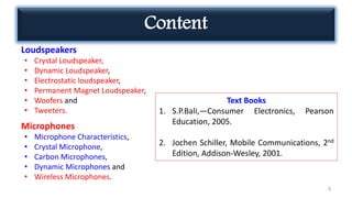
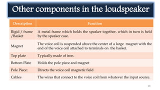
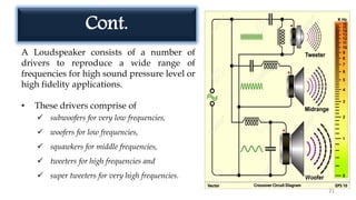
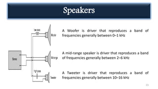
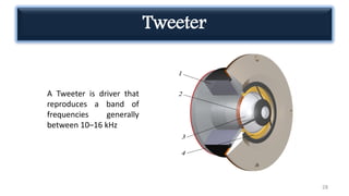
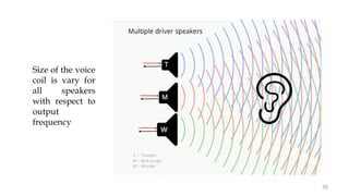
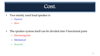


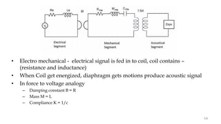
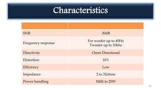
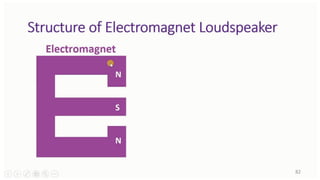
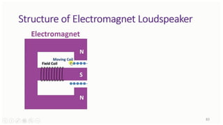
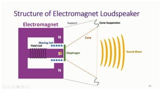


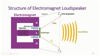


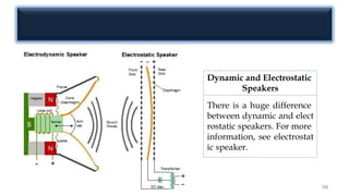
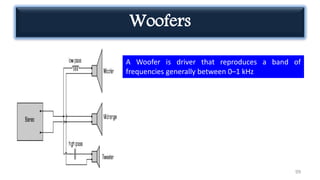


The document covers various types of consumer electronics, focusing specifically on loudspeakers and microphones, detailing their structure, function, and components. It describes different loudspeaker types such as dynamic, electrostatic, and crystal loudspeakers, along with their specific drivers like woofers, mid-range speakers, and tweeters. Additionally, it explains the principles of sound reproduction, the electroacoustic efficiency of speakers, and the technical considerations in designing effective loudspeakers.