Downloaded 242 times
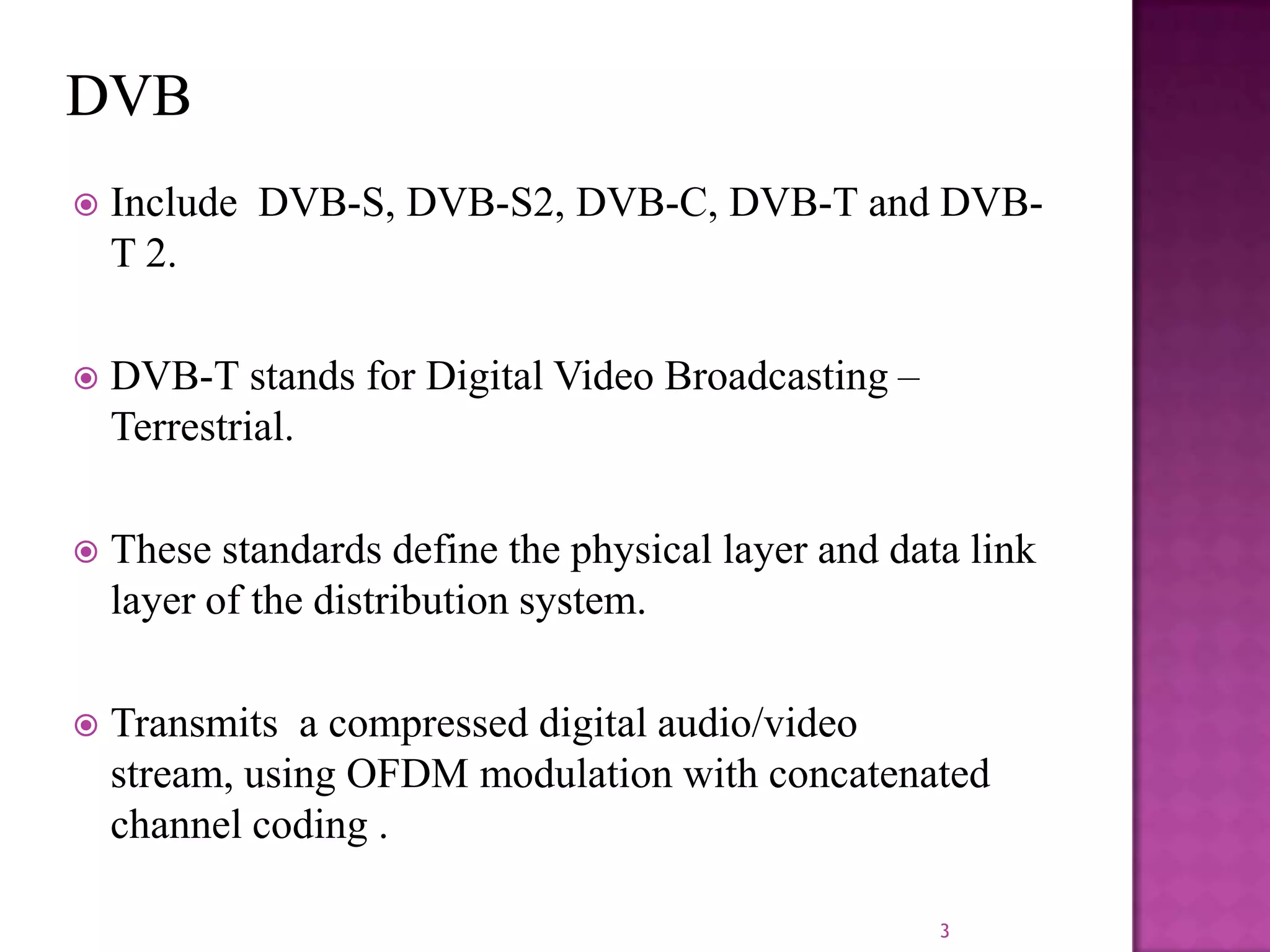


The document discusses the DVB-T2, an advanced digital video broadcasting standard, highlighting its history, architecture, and key technologies. It outlines the deployment timeline across various countries and explains the multiple modes of operation, including service-specific robustness and various interleaver techniques. The DVB-T2 standard presents new opportunities for terrestrial television delivery, making it crucial for future broadcasting developments.