Downloaded 1,010 times


![DVB-C DVB-C2
Input Interface
SingleTransport
Stream(TS)
MultipleTransport Stream andGeneric Stream Encapsulation(GSE)
Modes
Constant
Coding &Modulati
on
Variable Coding & Modulation and AdaptiveCoding & Modulation
FEC
Reed
Solomon (RS)
LDPC + BCH 1/2, 2/3, 3/4, 4/5, 5/6, 8/9, 9/10[4]
Modulation
Single
Carrier QAM
absolute OFDM[5]
Modulation
Schemes
16- to 256-QAM 16- to 4096-QAM
Guard Interval Not Applicable 1/64 or 1/128
Inverse Fast
Fourier
transform (IFFT)
size
Not Applicable 4k[6]
Interleaving Bit-Interleaving Bit-Time- and Frequency-Interleaving
Pilots Not Applicable Scattered andContinual Pilots](https://image.slidesharecdn.com/presentation1new-150201053618-conversion-gate01/75/Digital-Video-Broadcasting-DVB-18-2048.jpg)
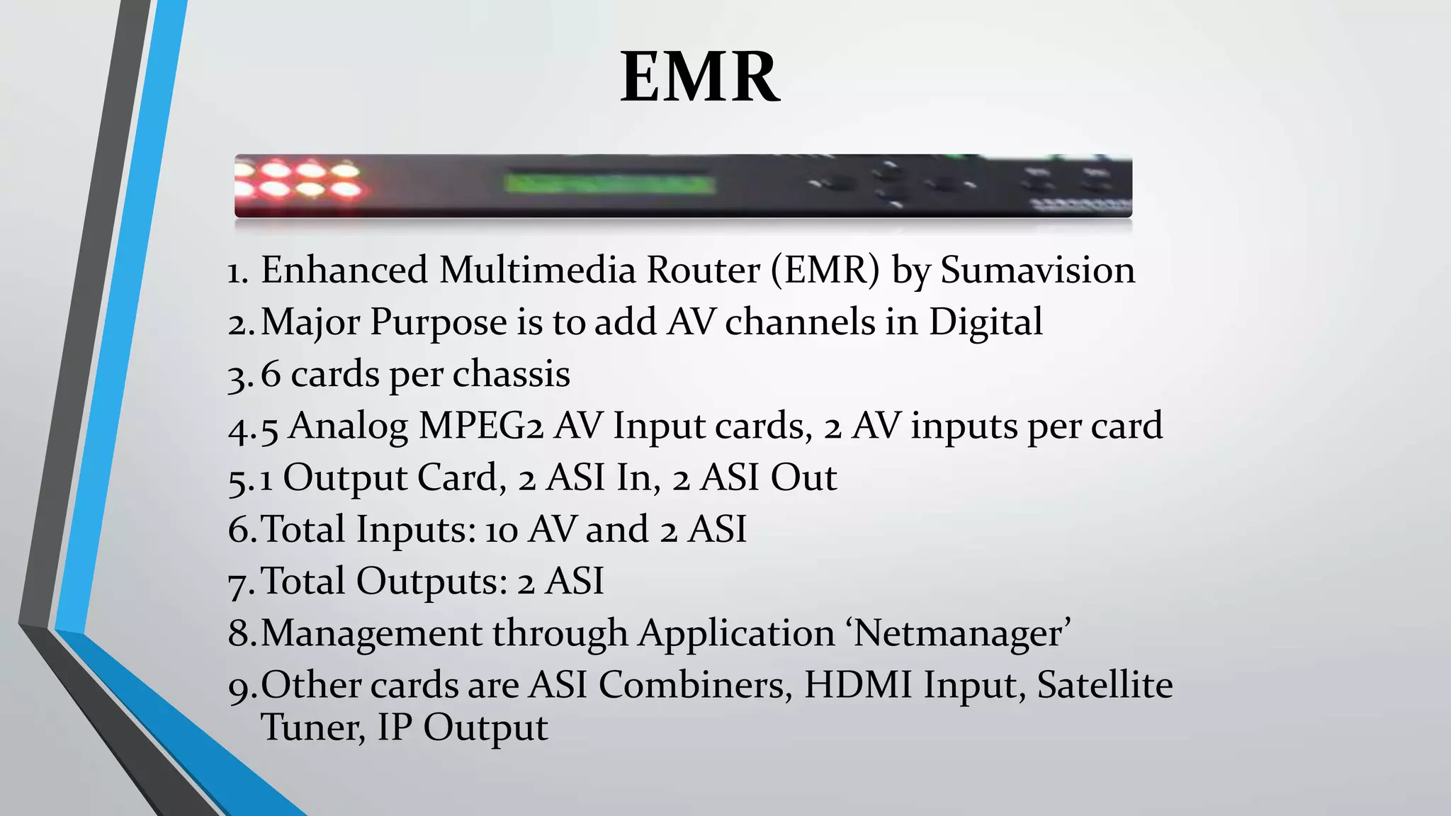
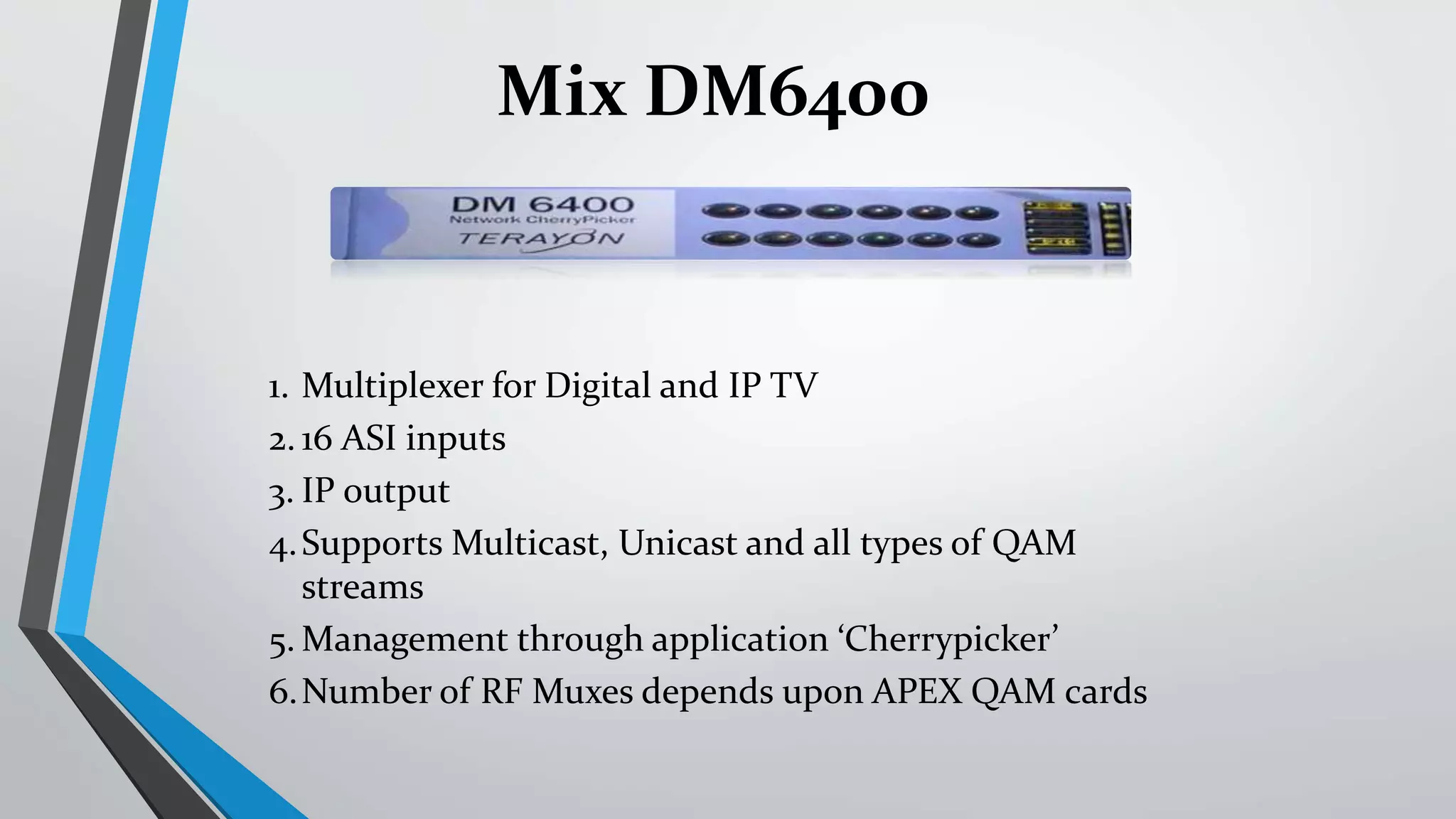
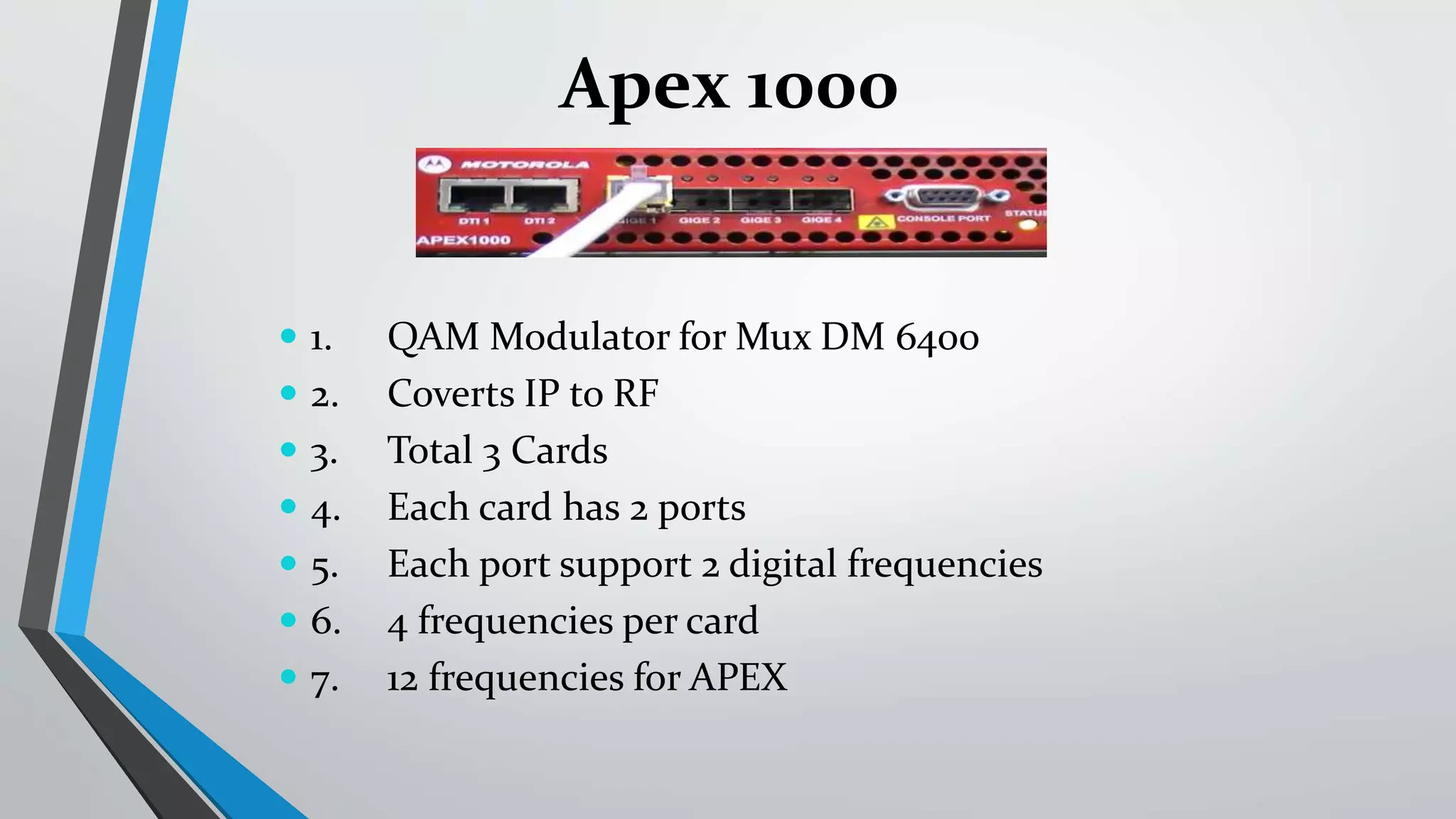
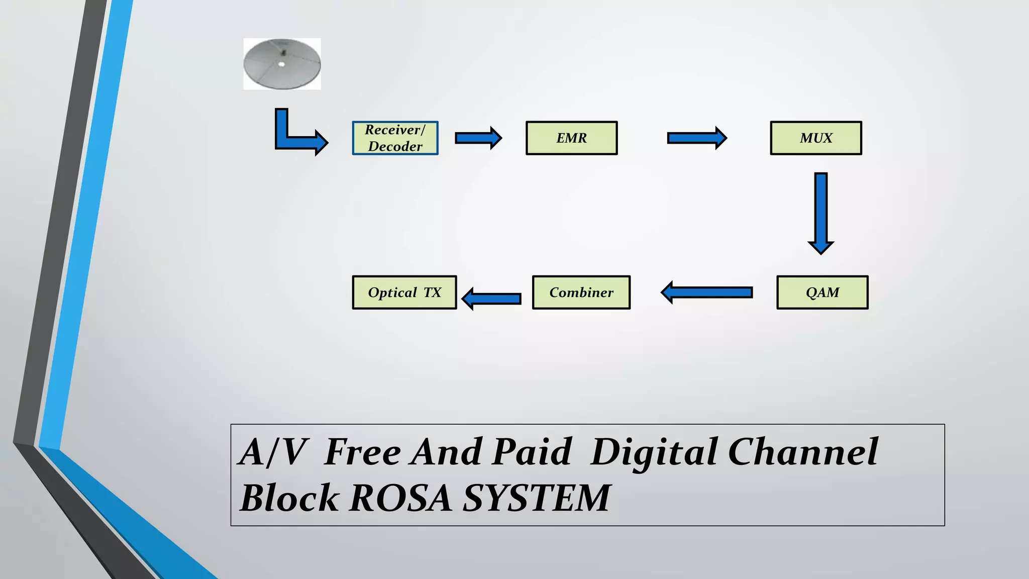
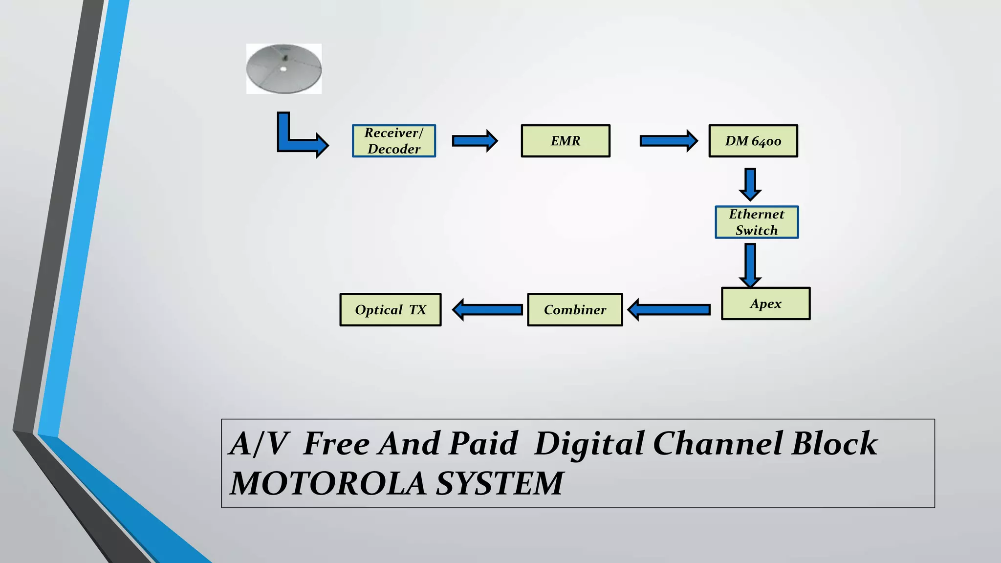


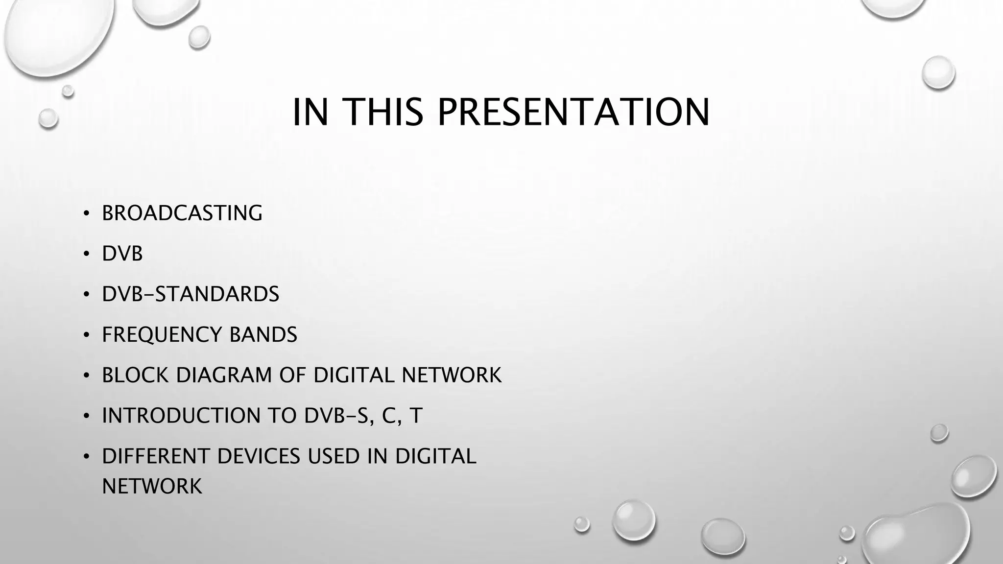
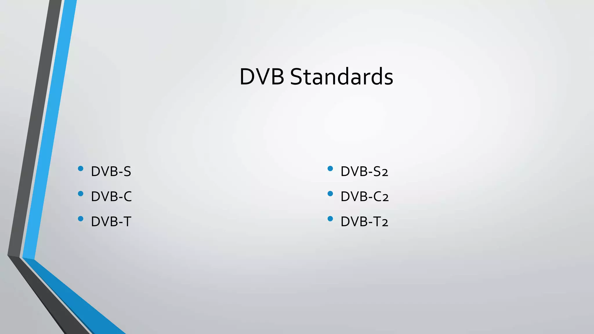
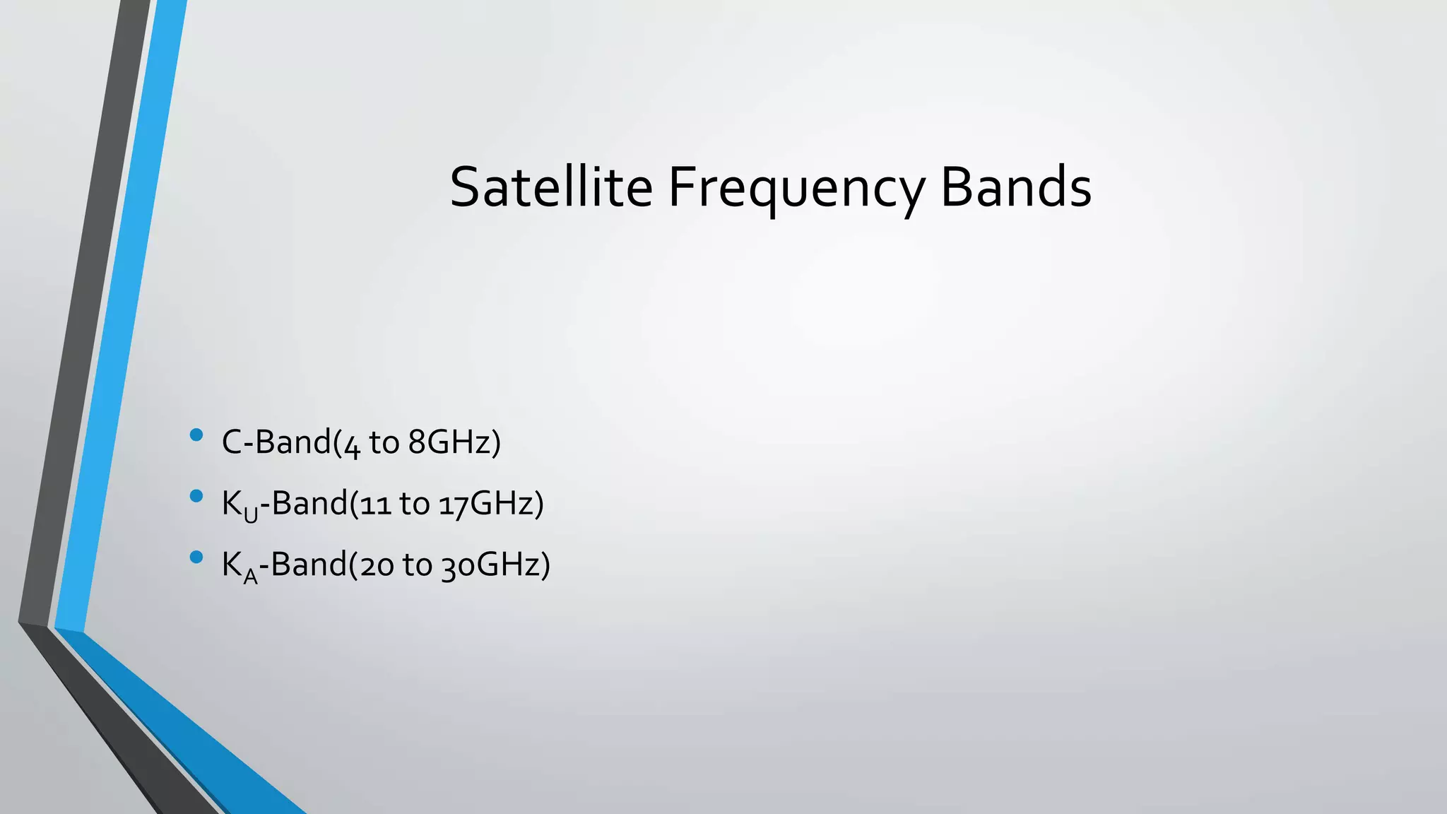
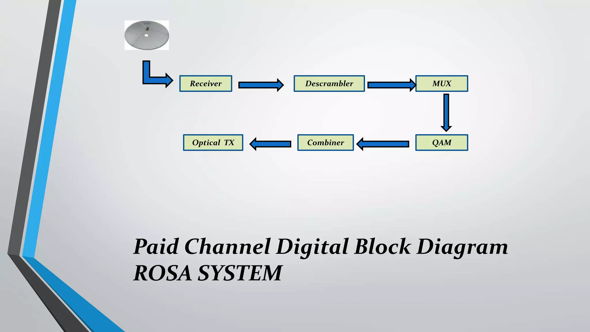
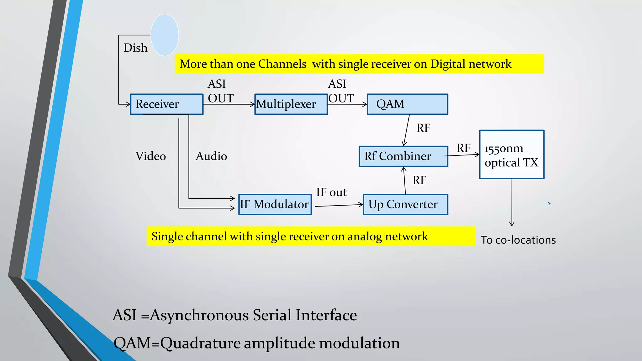
The presentation outlines digital video broadcasting (DVB) standards, including DVB-S, DVB-C, and DVB-T, explaining their functionalities and differences. It details the frequency bands used and the modulation techniques like QAM and QPSK, as well as advancements in DVB technology such as DVB-S2 and DVB-C2 allowing higher bitrates. The document also discusses various devices involved in broadcasting systems, including multiplexers and modulators, and their roles in digital network infrastructure.