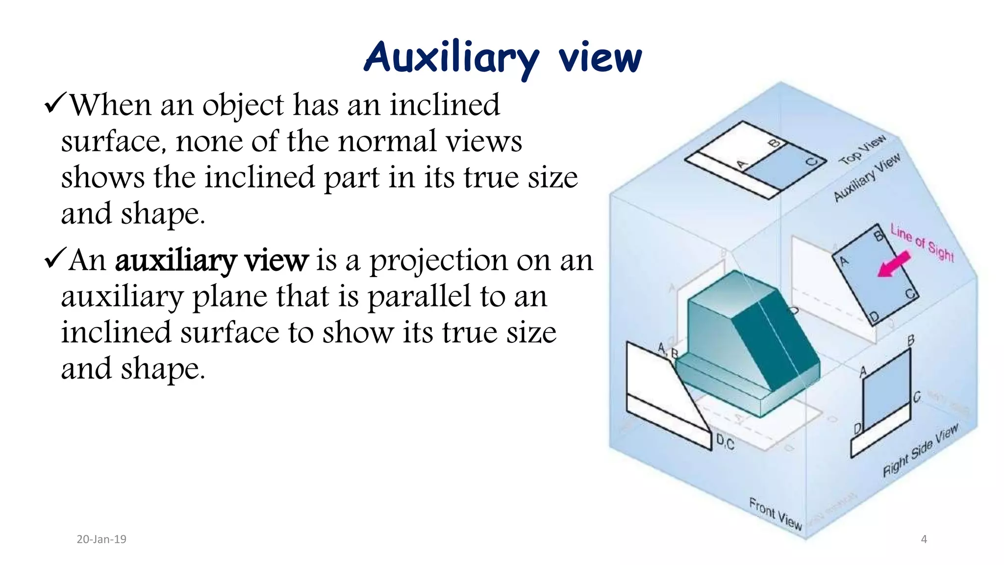
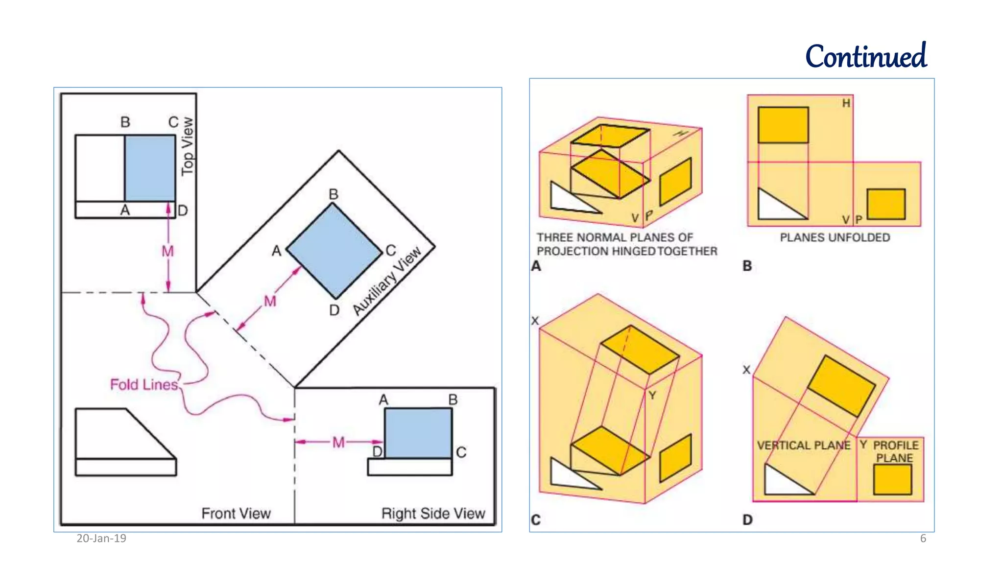
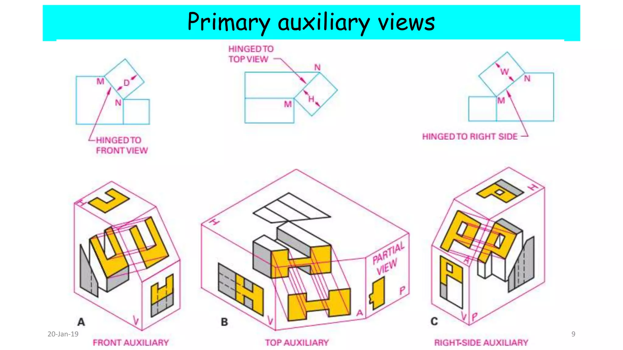
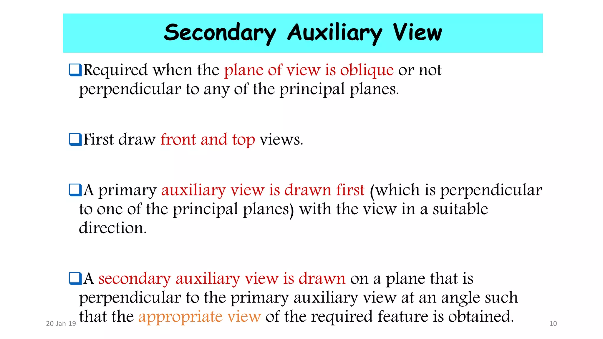
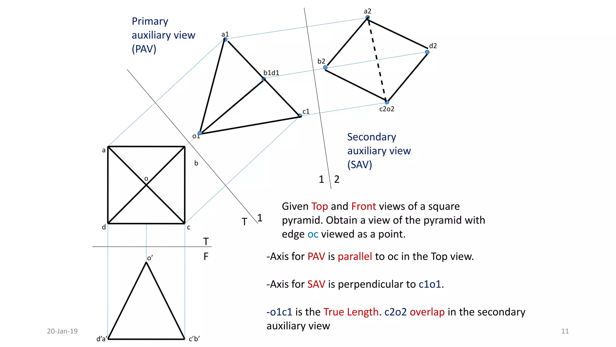
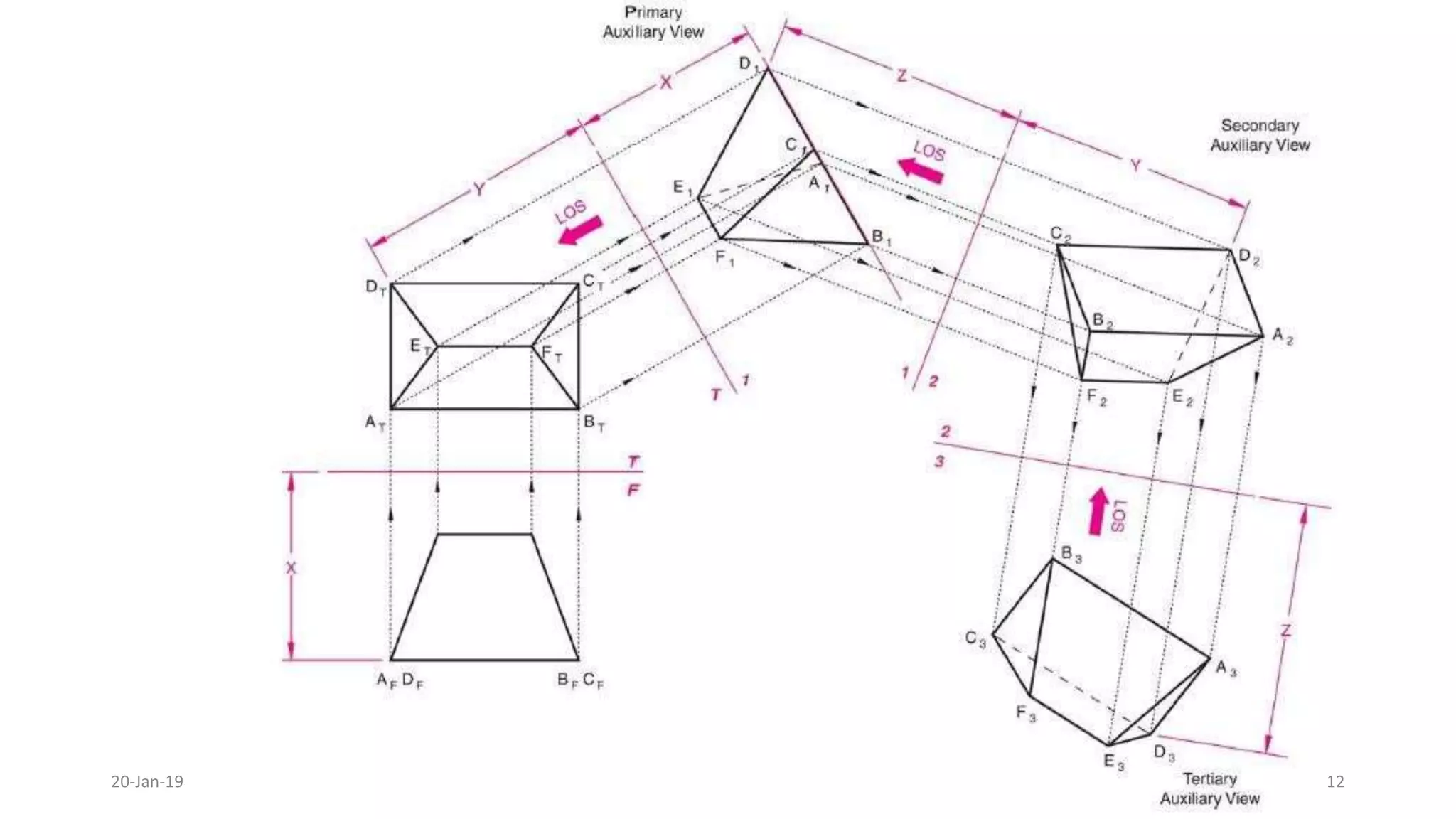
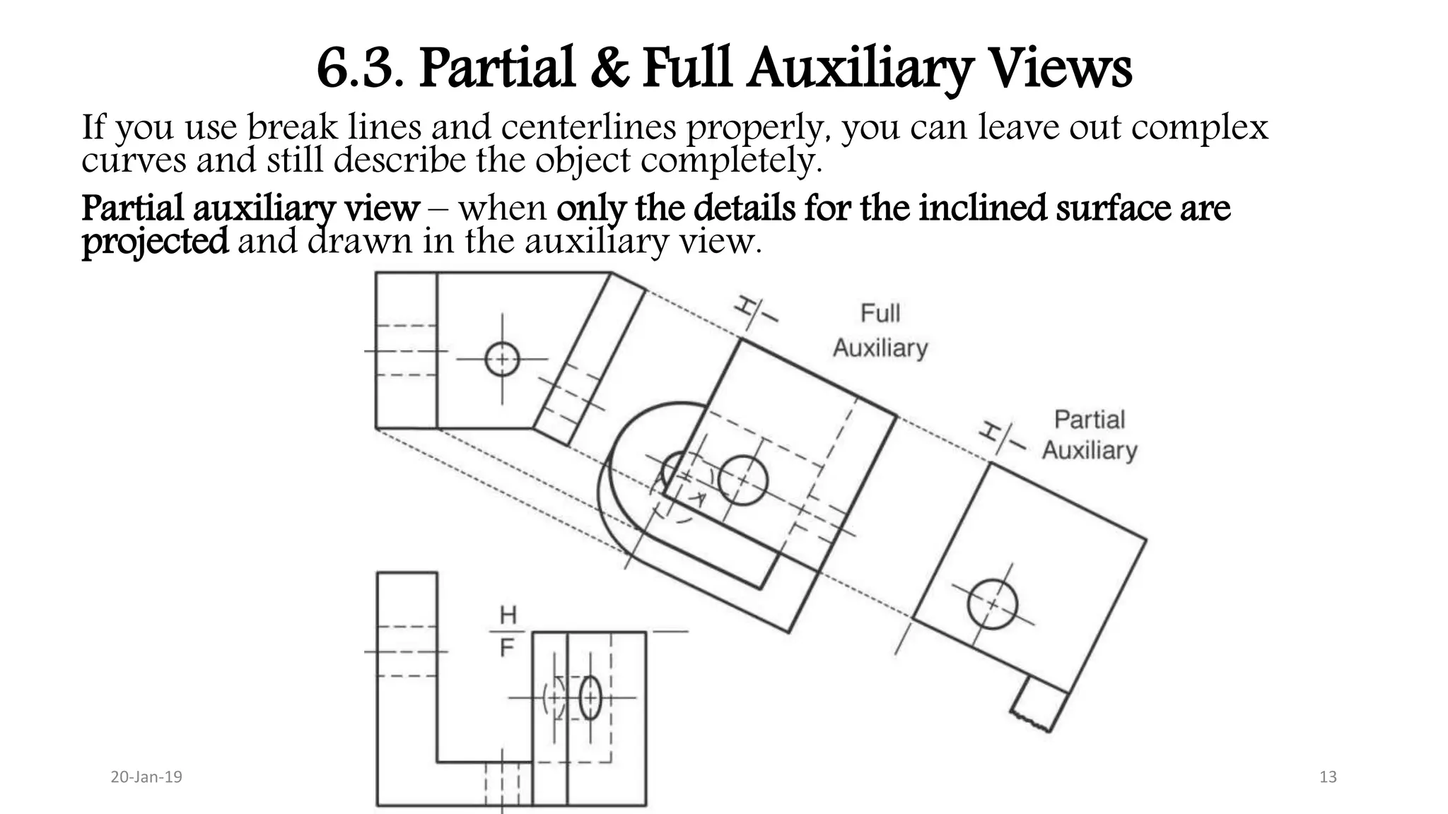
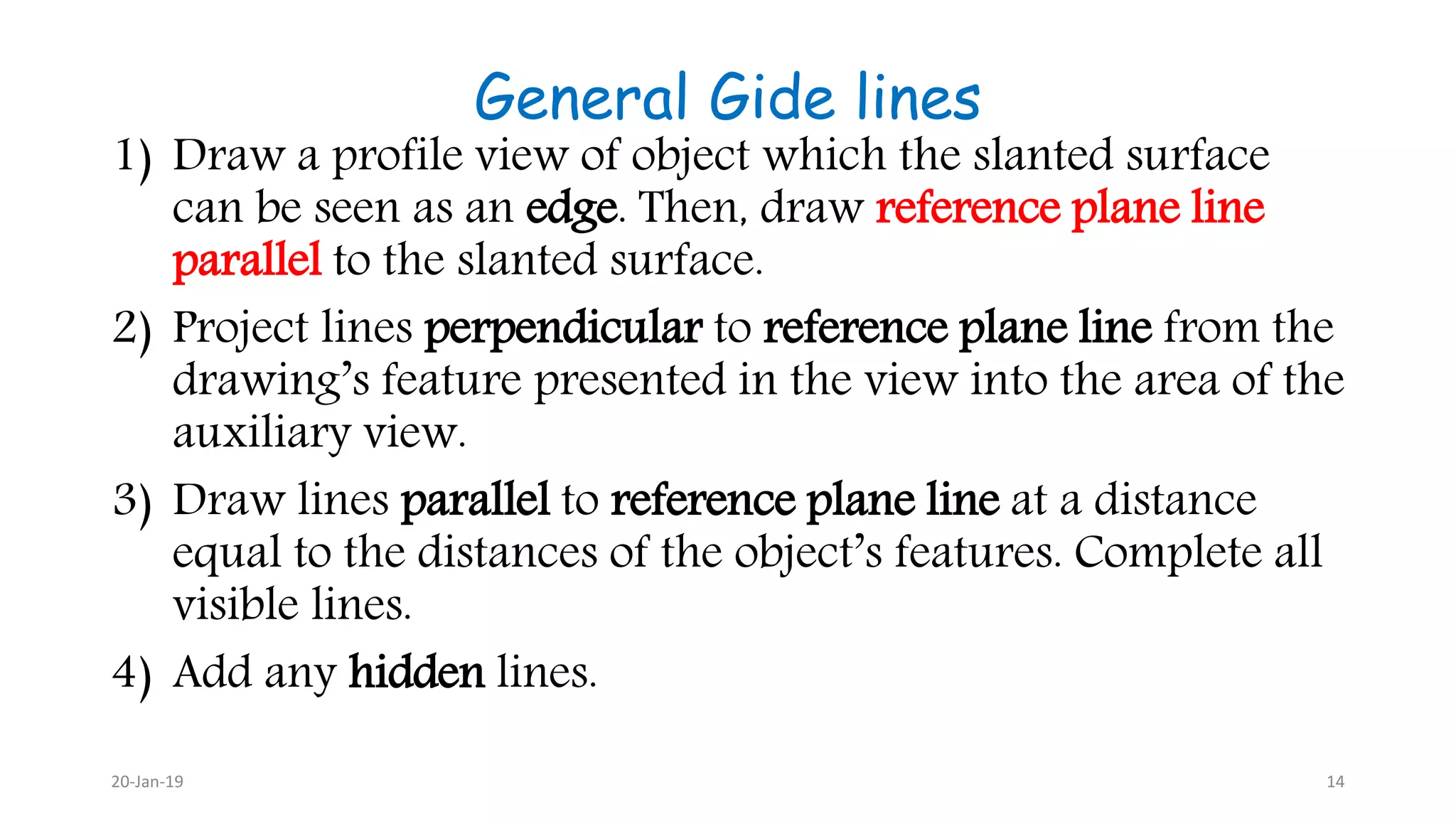
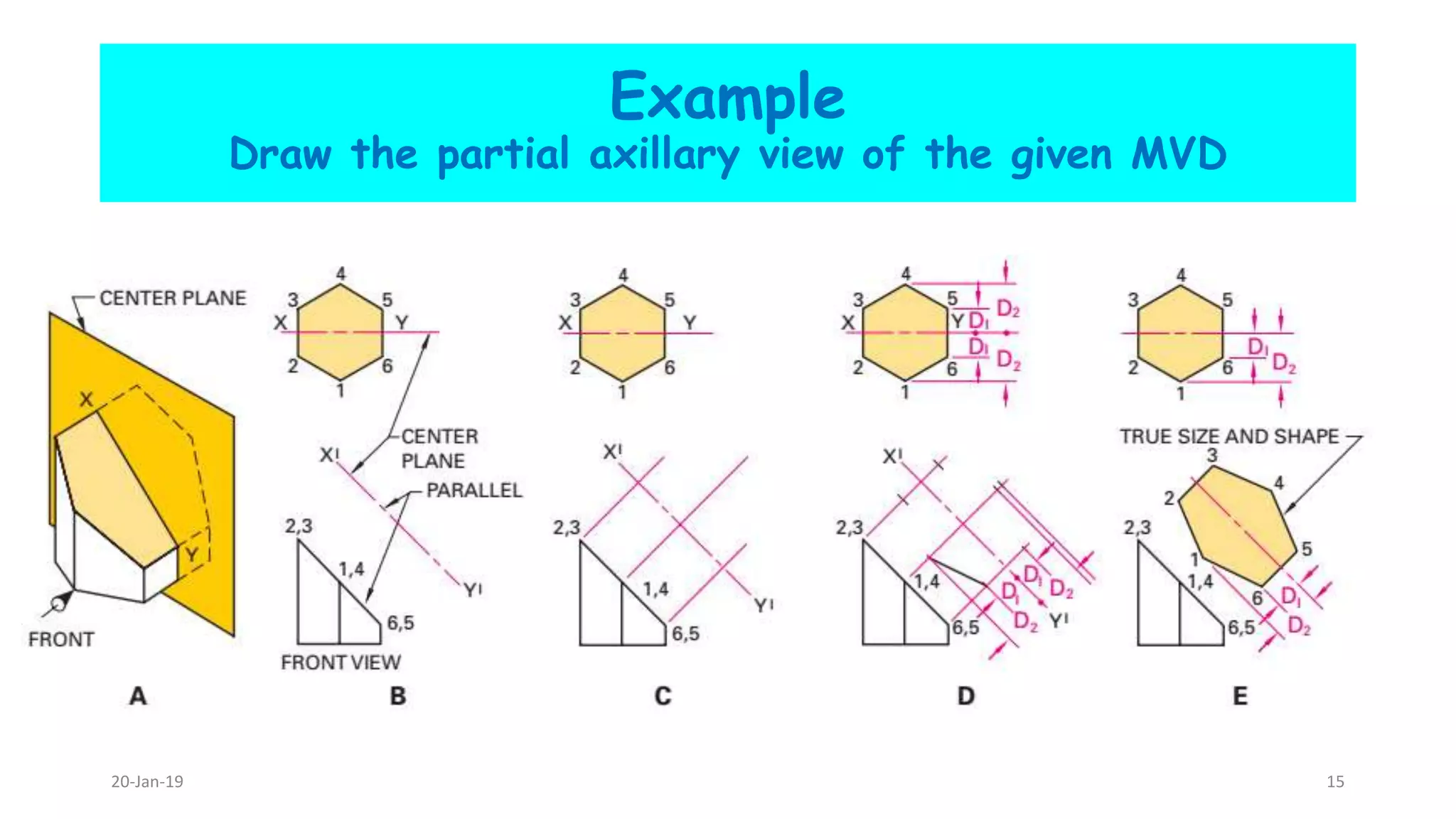
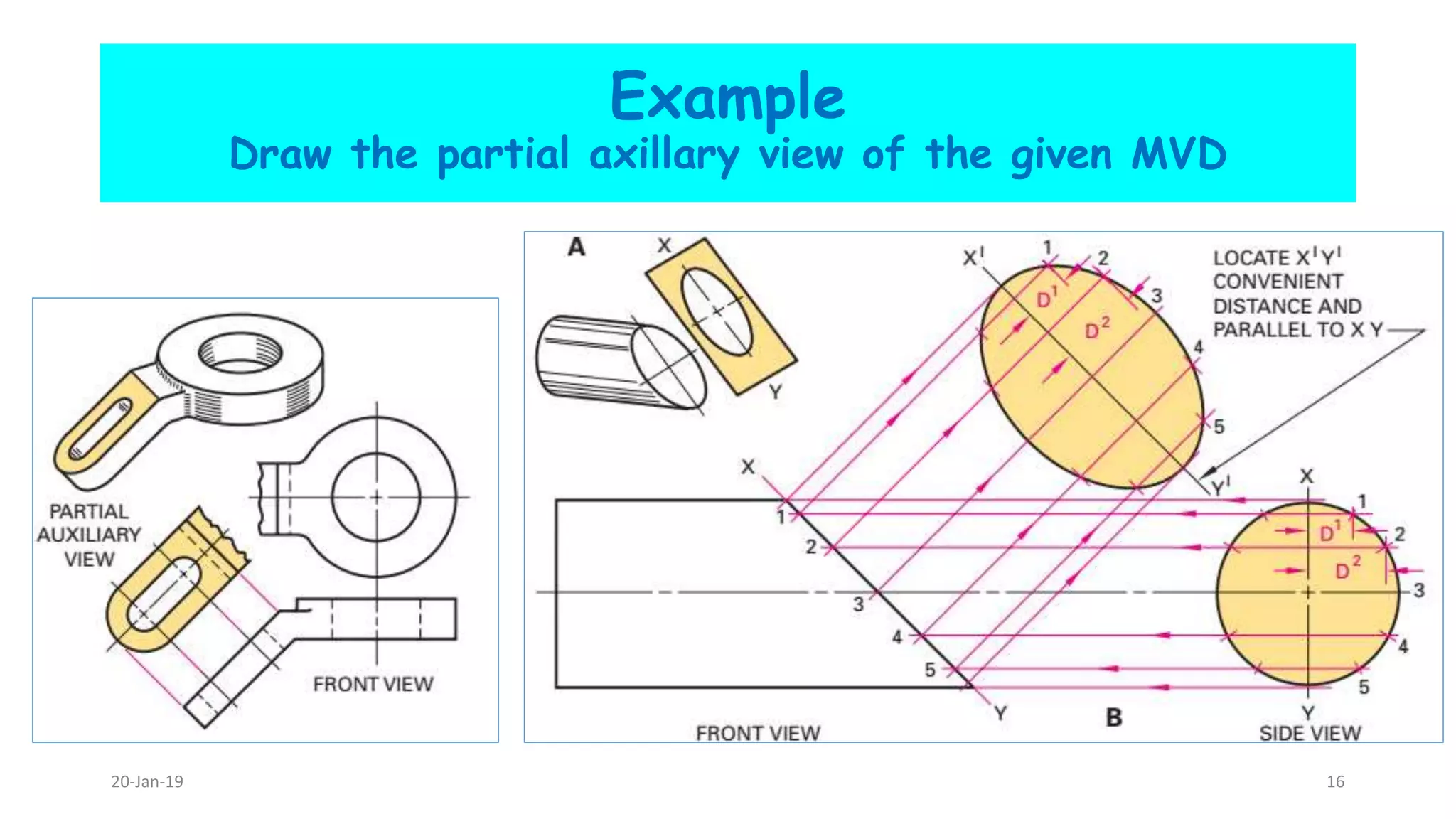
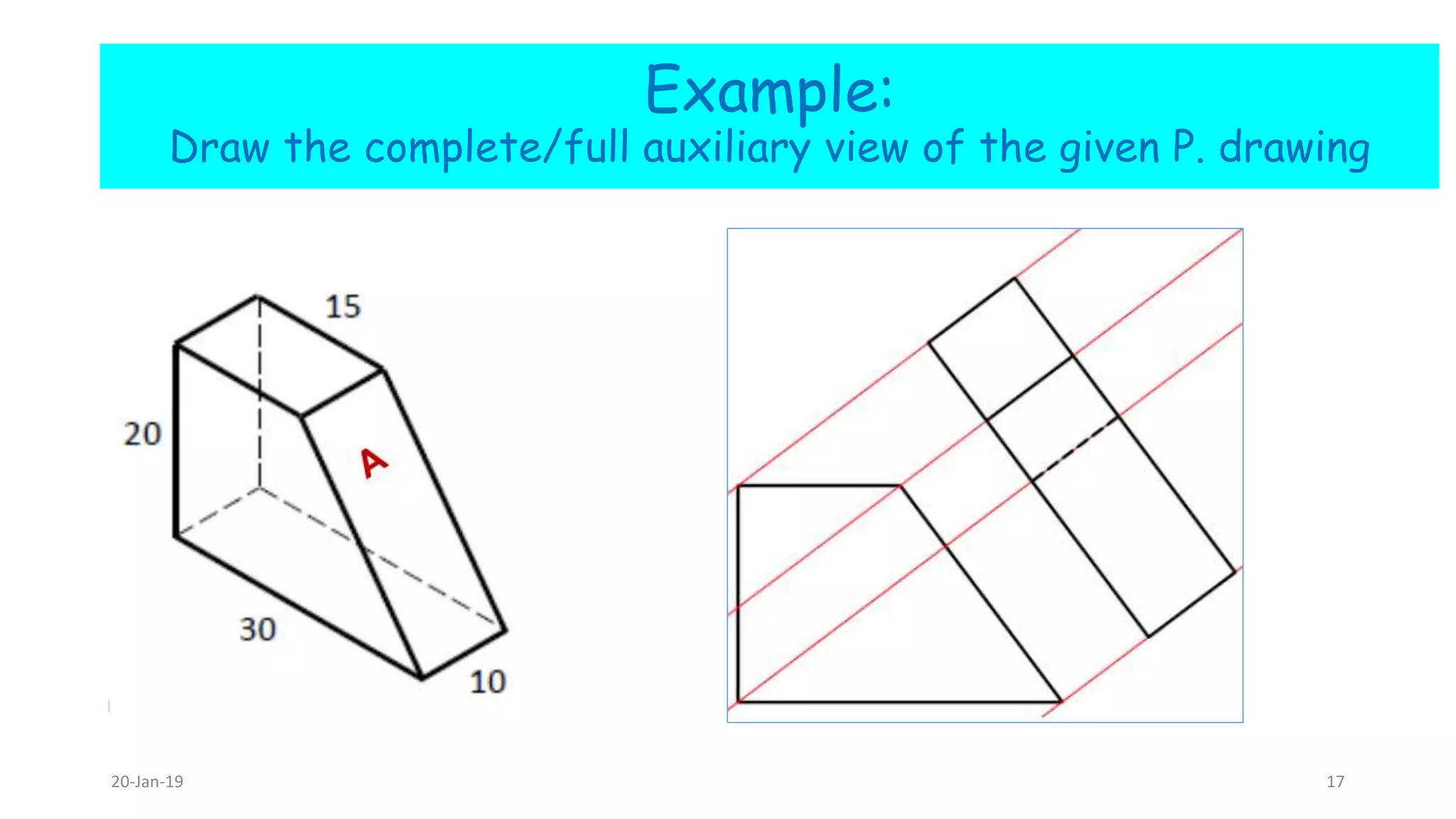
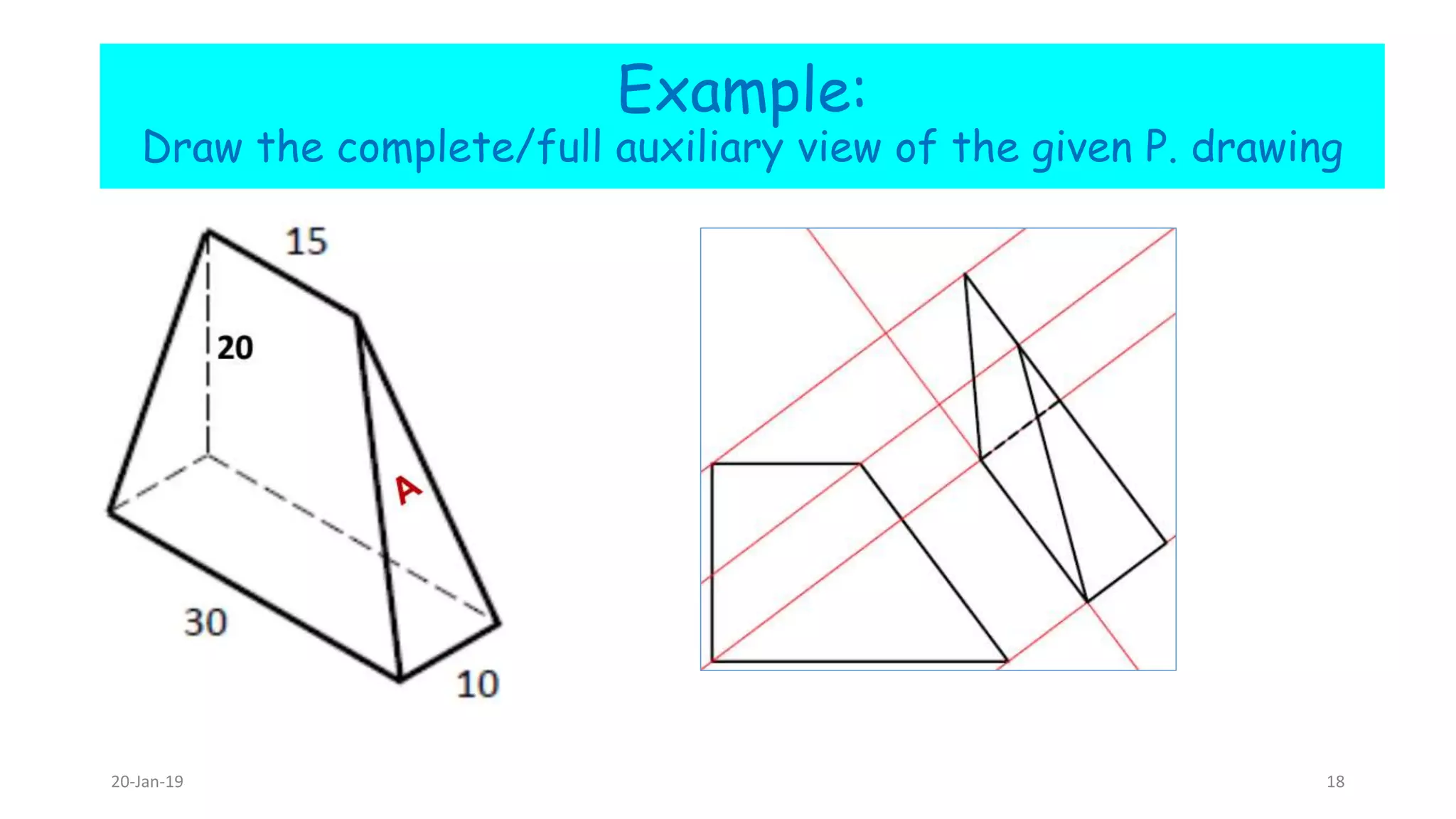
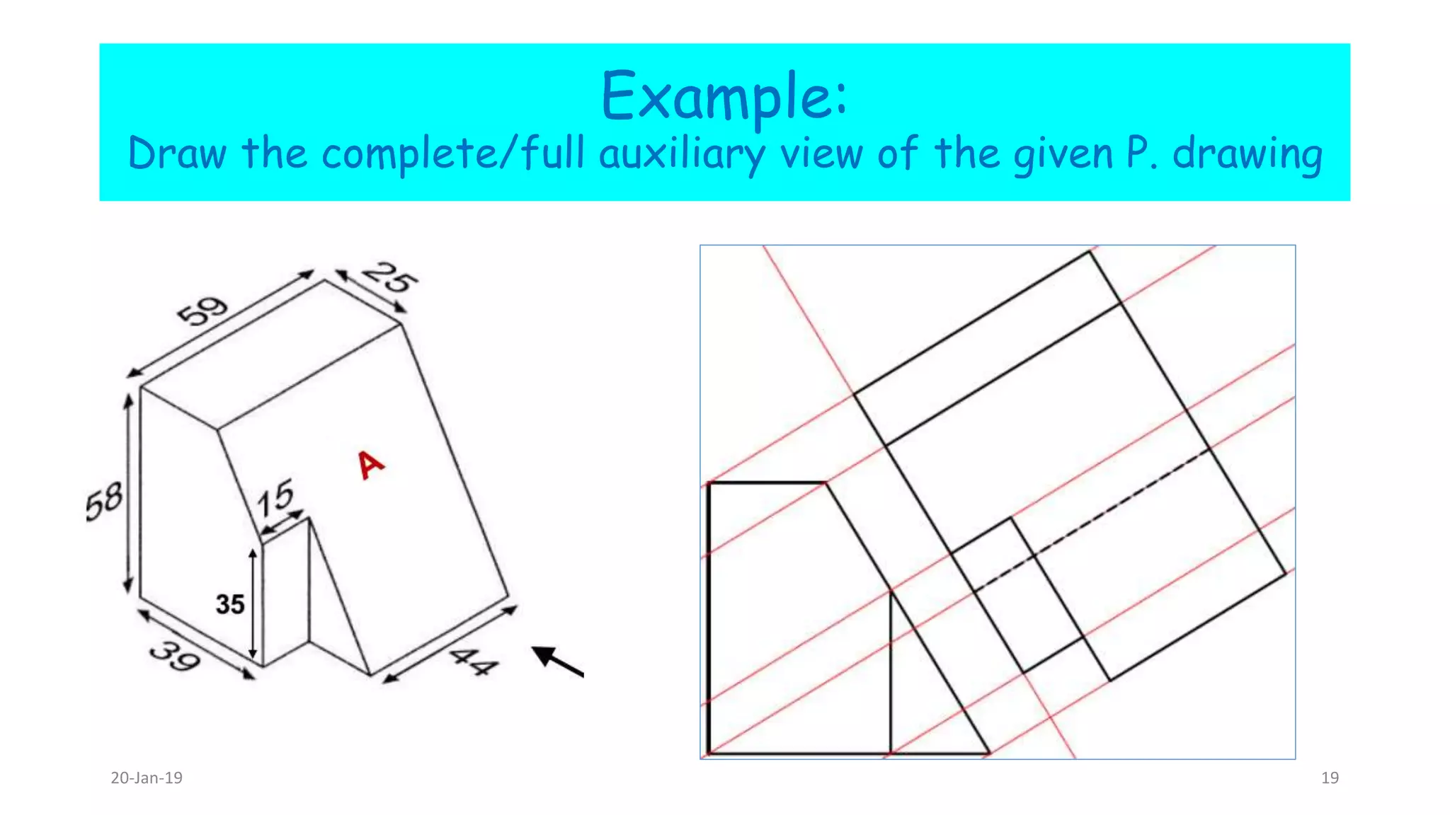
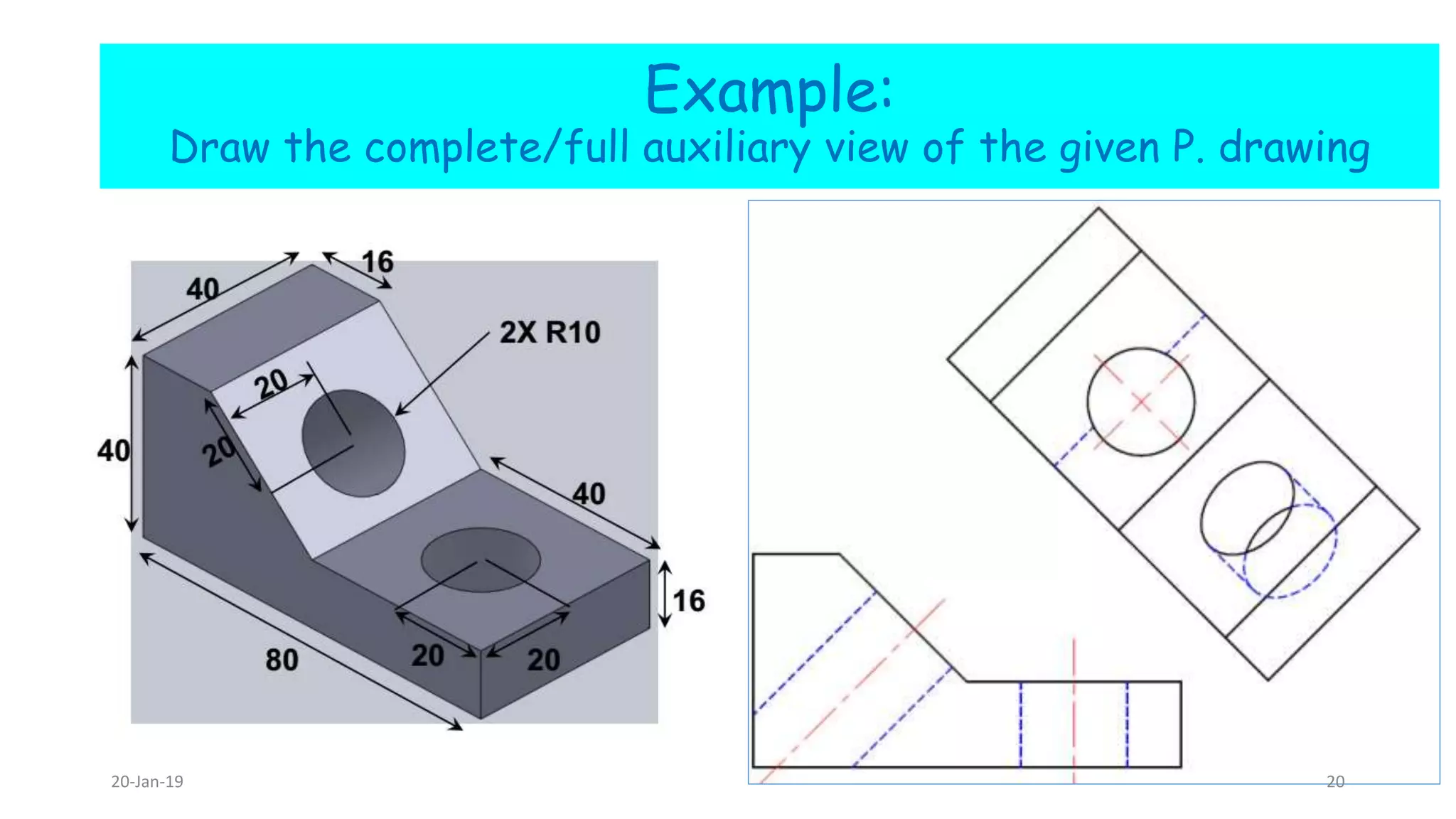
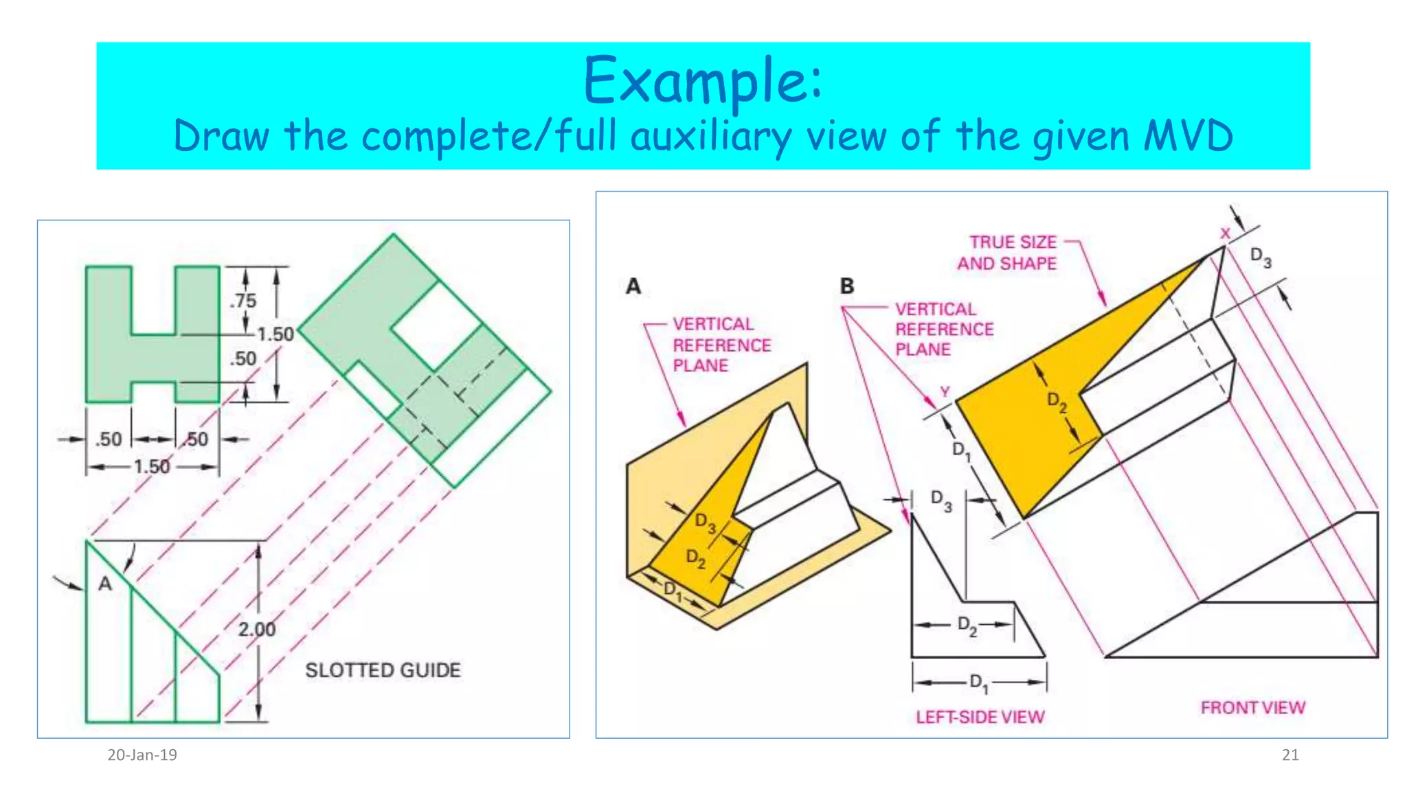
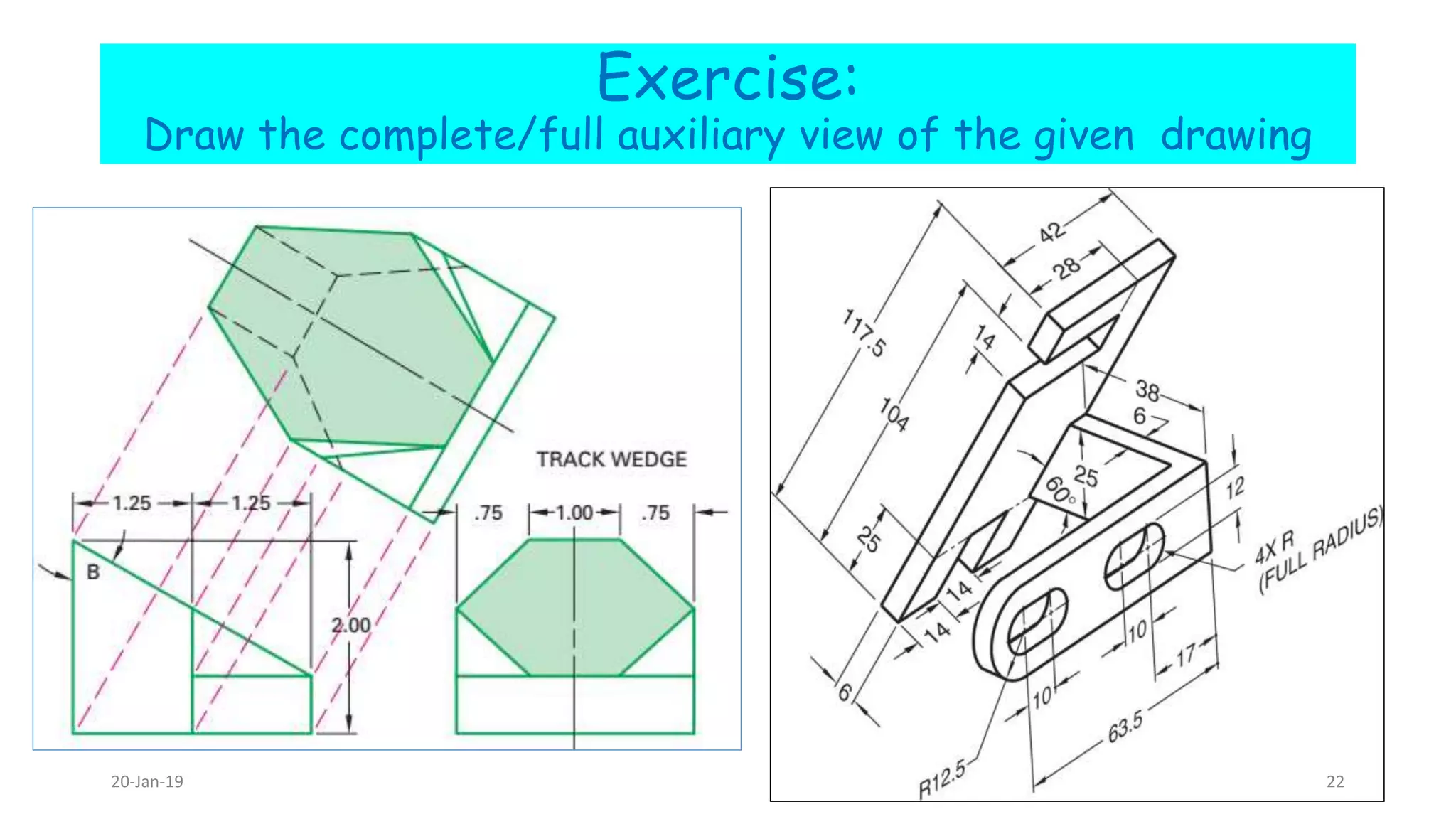
6. Auxiliaryview
Complied By: Habtamu Geremew
Email: habti.geremew@gmail.com
Gondar institute of Technology
Engineering Drawing.
Objectives
At the end of this lesson, students should:
Clearly understand the advantage of auxiliary projection
show the classification of auxiliary view in different
perspective
Relate different engineering features to the conceptual
one
Have the ability to draw partial and complete auxiliary
views.
20-Jan-19 2
Welcome to auxiliary view
20-Jan-19 3
Auxiliary view
When an object has an inclined
surface, none of the normal views
shows the inclined part in its true size
and shape.
An auxiliary view is a projection on an
auxiliary plane that is parallel to an
inclined surface to show its true size
and shape.
20-Jan-19 4
6.1. Auxiliary View Projection Theory
Auxiliary View – An orthographic view that is projected
onto any plane other than one of the 6 principal views.
Auxiliary views are orthographic views used to present
true-shaped views of slanted and oblique surfaces.
A true size and shape plane is shown only when the line of
sight used to create the view is perpendicular to the
projection plane.
20-Jan-19 5
Continued
20-Jan-19 6
6.2. Auxiliary View Classifications
Auxiliary views are classified according to their origin and
from which of the three normal planes they are developed.
Auxiliary views are classified as: primary, secondary or
tertiary;
1. Primary auxiliary view – a single view projected from one
of the six principal views.
2. Secondary auxiliary view – a single view projected from a
primary auxiliary view.
3. Tertiary auxiliary view – a single view projected from a
secondary or another tertiary auxiliary view
20-Jan-19 7
Primary auxiliary view
A primary auxiliary view is one that is developed directly from the normal
views. There are three primary auxiliary views.
1) Depth Auxiliary View – projected from the front view, and the depth
dimension is true length. When an auxiliary view is hinged on the front
view, the view is a front auxiliary view. The primary reference of the
front auxiliary view is depth.
2) Height Auxiliary View/top auxiliary view– projected from the top view,
and the height dimension is shown true length.
3) Width Auxiliary View/ side auxiliary view– projected from the profile
view, and the width dimension is shown true length.
20-Jan-19 8
Primary auxiliary views
20-Jan-19 9
Secondary Auxiliary View
Required when the plane of view is oblique or not
perpendicular to any of the principal planes.
First draw front and top views.
A primary auxiliary view is drawn first (which is perpendicular
to one of the principal planes) with the view in a suitable
direction.
A secondary auxiliary view is drawn on a plane that is
perpendicular to the primary auxiliary view at an angle such
that the appropriate view of the required feature is obtained.20-Jan-19 10
T 1
c1
a1
b1d1
o1
c
a
d
o’
d’a’
b
c’b’
o
b2
d2
a2
c2o2
Given Top and Front views of a square
pyramid. Obtain a view of the pyramid with
edge oc viewed as a point.
T
F
1 2
-Axis for PAV is parallel to oc in the Top view.
-Axis for SAV is perpendicular to c1o1.
-o1c1 is the True Length. c2o2 overlap in the secondary
auxiliary view
Primary
auxiliary view
(PAV)
Secondary
auxiliary view
(SAV)
20-Jan-19 11
20-Jan-19 12
6.3. Partial & Full Auxiliary Views
If you use break lines and centerlines properly, you can leave out complex
curves and still describe the object completely.
Partial auxiliary view – when only the details for the inclined surface are
projected and drawn in the auxiliary view.
20-Jan-19 13
General Gide lines
1) Draw a profile view of object which the slanted surface
can be seen as an edge. Then, draw reference plane line
parallel to the slanted surface.
2) Project lines perpendicular to reference plane line from the
drawing’s feature presented in the view into the area of the
auxiliary view.
3) Draw lines parallel to reference plane line at a distance
equal to the distances of the object’s features. Complete all
visible lines.
4) Add any hidden lines.
20-Jan-19 14
Example
Draw the partial axillary view of the given MVD
20-Jan-19 15
Example
Draw the partial axillary view of the given MVD
20-Jan-19 16
Example:
Draw the complete/full auxiliary view of the given P. drawing
20-Jan-19 17
Example:
Draw the complete/full auxiliary view of the given P. drawing
20-Jan-19 18
Example:
Draw the complete/full auxiliary view of the given P. drawing
20-Jan-19 19
Example:
Draw the complete/full auxiliary view of the given P. drawing
20-Jan-19 20
Example:
Draw the complete/full auxiliary view of the given MVD
20-Jan-19 21
Exercise:
Draw the complete/full auxiliary view of the given drawing
20-Jan-19 22
Th a n k You
Ver y M uc h
Comment/question session
So now what are you
going to do?
Department of Mechanical Engineering20-Jan-19 23

Axulliary view

  • 1.
    6. Auxiliaryview Complied By:Habtamu Geremew Email: habti.geremew@gmail.com Gondar institute of Technology Engineering Drawing.
  • 2.
    Objectives At the endof this lesson, students should: Clearly understand the advantage of auxiliary projection show the classification of auxiliary view in different perspective Relate different engineering features to the conceptual one Have the ability to draw partial and complete auxiliary views. 20-Jan-19 2
  • 3.
    Welcome to auxiliaryview 20-Jan-19 3
  • 4.
    Auxiliary view When anobject has an inclined surface, none of the normal views shows the inclined part in its true size and shape. An auxiliary view is a projection on an auxiliary plane that is parallel to an inclined surface to show its true size and shape. 20-Jan-19 4
  • 5.
    6.1. Auxiliary ViewProjection Theory Auxiliary View – An orthographic view that is projected onto any plane other than one of the 6 principal views. Auxiliary views are orthographic views used to present true-shaped views of slanted and oblique surfaces. A true size and shape plane is shown only when the line of sight used to create the view is perpendicular to the projection plane. 20-Jan-19 5
  • 6.
  • 7.
    6.2. Auxiliary ViewClassifications Auxiliary views are classified according to their origin and from which of the three normal planes they are developed. Auxiliary views are classified as: primary, secondary or tertiary; 1. Primary auxiliary view – a single view projected from one of the six principal views. 2. Secondary auxiliary view – a single view projected from a primary auxiliary view. 3. Tertiary auxiliary view – a single view projected from a secondary or another tertiary auxiliary view 20-Jan-19 7
  • 8.
    Primary auxiliary view Aprimary auxiliary view is one that is developed directly from the normal views. There are three primary auxiliary views. 1) Depth Auxiliary View – projected from the front view, and the depth dimension is true length. When an auxiliary view is hinged on the front view, the view is a front auxiliary view. The primary reference of the front auxiliary view is depth. 2) Height Auxiliary View/top auxiliary view– projected from the top view, and the height dimension is shown true length. 3) Width Auxiliary View/ side auxiliary view– projected from the profile view, and the width dimension is shown true length. 20-Jan-19 8
  • 9.
  • 10.
    Secondary Auxiliary View Requiredwhen the plane of view is oblique or not perpendicular to any of the principal planes. First draw front and top views. A primary auxiliary view is drawn first (which is perpendicular to one of the principal planes) with the view in a suitable direction. A secondary auxiliary view is drawn on a plane that is perpendicular to the primary auxiliary view at an angle such that the appropriate view of the required feature is obtained.20-Jan-19 10
  • 11.
    T 1 c1 a1 b1d1 o1 c a d o’ d’a’ b c’b’ o b2 d2 a2 c2o2 Given Topand Front views of a square pyramid. Obtain a view of the pyramid with edge oc viewed as a point. T F 1 2 -Axis for PAV is parallel to oc in the Top view. -Axis for SAV is perpendicular to c1o1. -o1c1 is the True Length. c2o2 overlap in the secondary auxiliary view Primary auxiliary view (PAV) Secondary auxiliary view (SAV) 20-Jan-19 11
  • 12.
  • 13.
    6.3. Partial &Full Auxiliary Views If you use break lines and centerlines properly, you can leave out complex curves and still describe the object completely. Partial auxiliary view – when only the details for the inclined surface are projected and drawn in the auxiliary view. 20-Jan-19 13
  • 14.
    General Gide lines 1)Draw a profile view of object which the slanted surface can be seen as an edge. Then, draw reference plane line parallel to the slanted surface. 2) Project lines perpendicular to reference plane line from the drawing’s feature presented in the view into the area of the auxiliary view. 3) Draw lines parallel to reference plane line at a distance equal to the distances of the object’s features. Complete all visible lines. 4) Add any hidden lines. 20-Jan-19 14
  • 15.
    Example Draw the partialaxillary view of the given MVD 20-Jan-19 15
  • 16.
    Example Draw the partialaxillary view of the given MVD 20-Jan-19 16
  • 17.
    Example: Draw the complete/fullauxiliary view of the given P. drawing 20-Jan-19 17
  • 18.
    Example: Draw the complete/fullauxiliary view of the given P. drawing 20-Jan-19 18
  • 19.
    Example: Draw the complete/fullauxiliary view of the given P. drawing 20-Jan-19 19
  • 20.
    Example: Draw the complete/fullauxiliary view of the given P. drawing 20-Jan-19 20
  • 21.
    Example: Draw the complete/fullauxiliary view of the given MVD 20-Jan-19 21
  • 22.
    Exercise: Draw the complete/fullauxiliary view of the given drawing 20-Jan-19 22
  • 23.
    Th a nk You Ver y M uc h Comment/question session So now what are you going to do? Department of Mechanical Engineering20-Jan-19 23