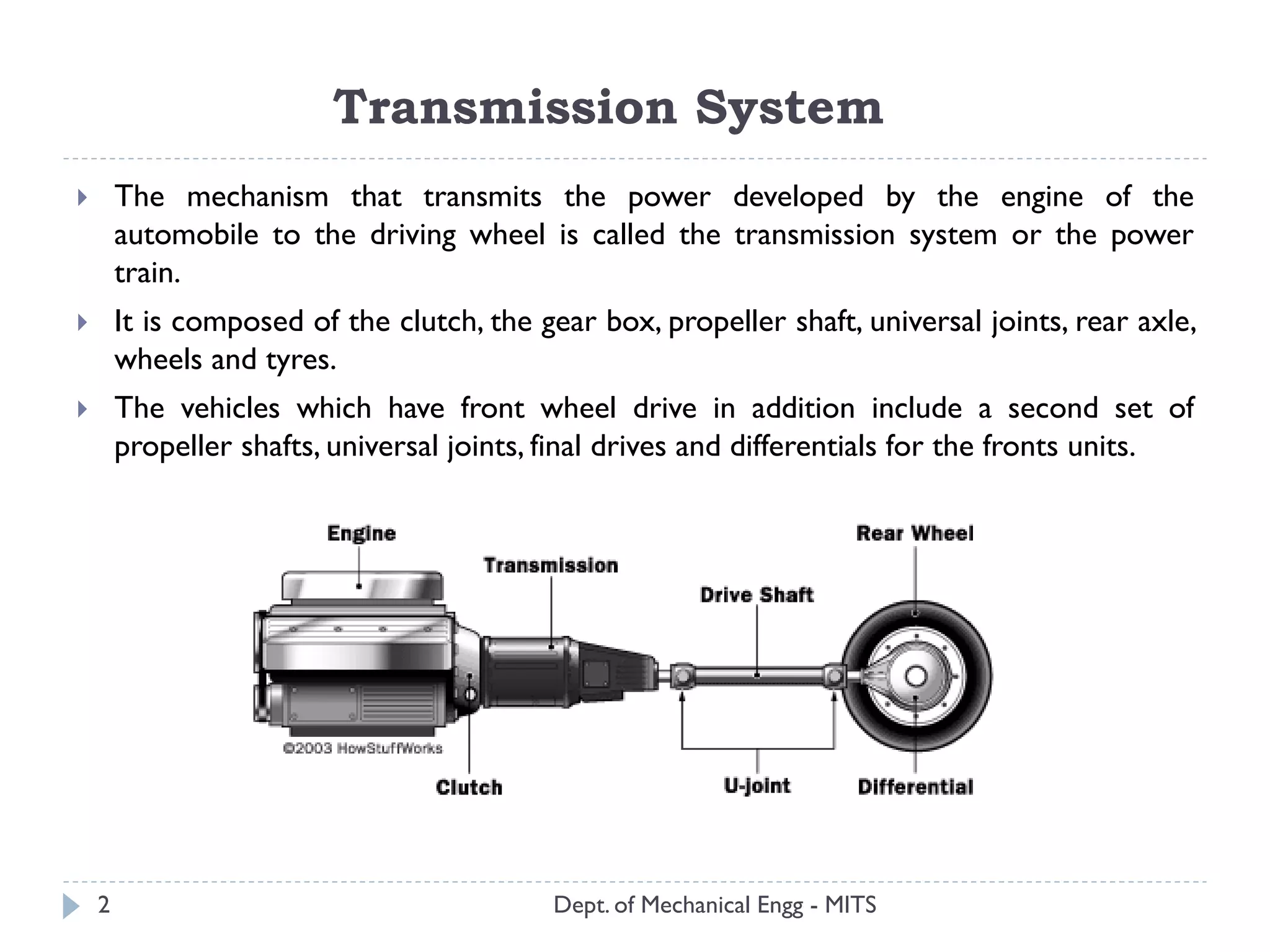
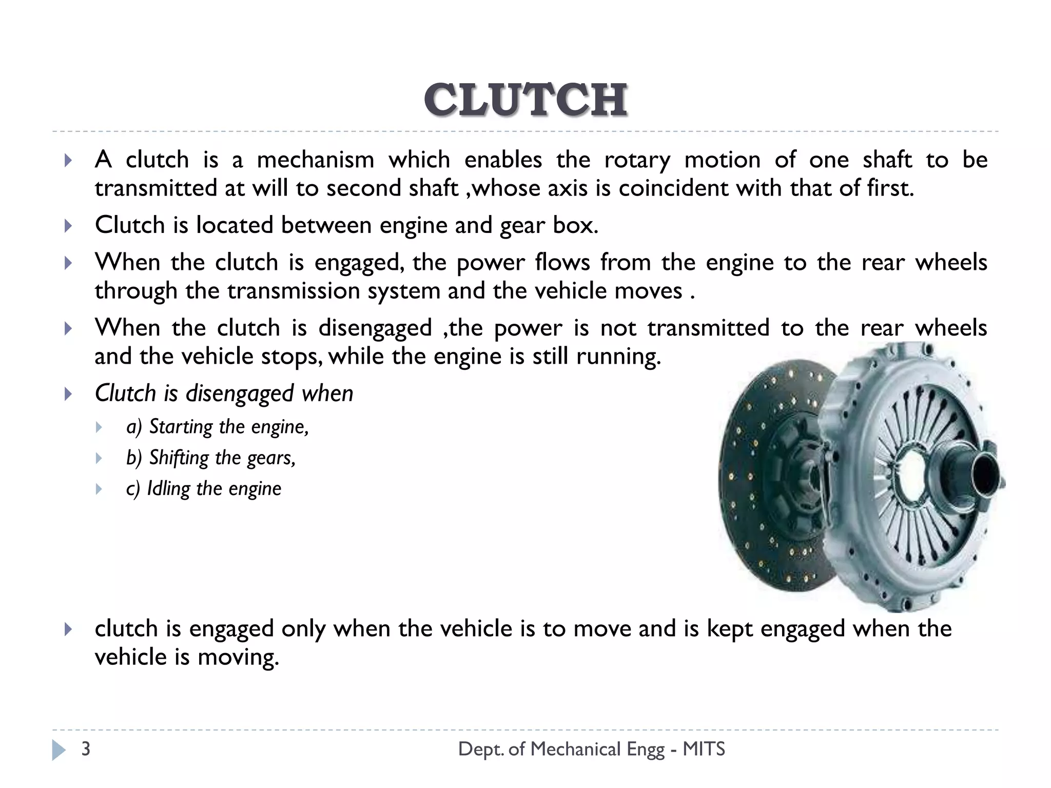
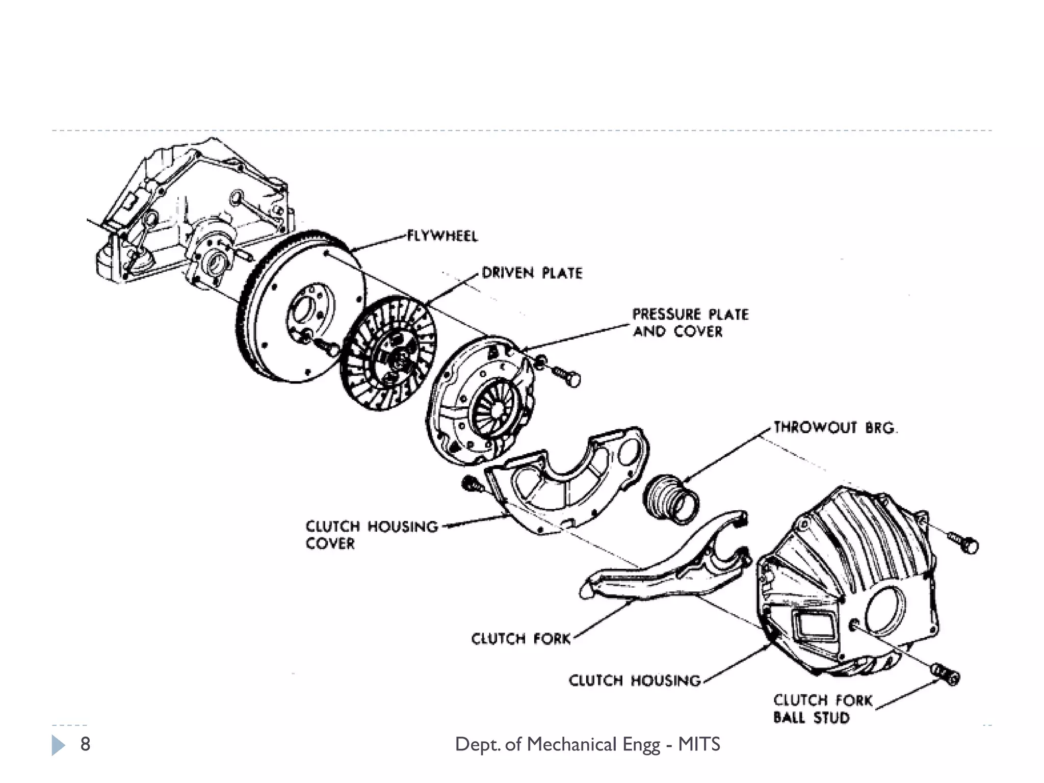
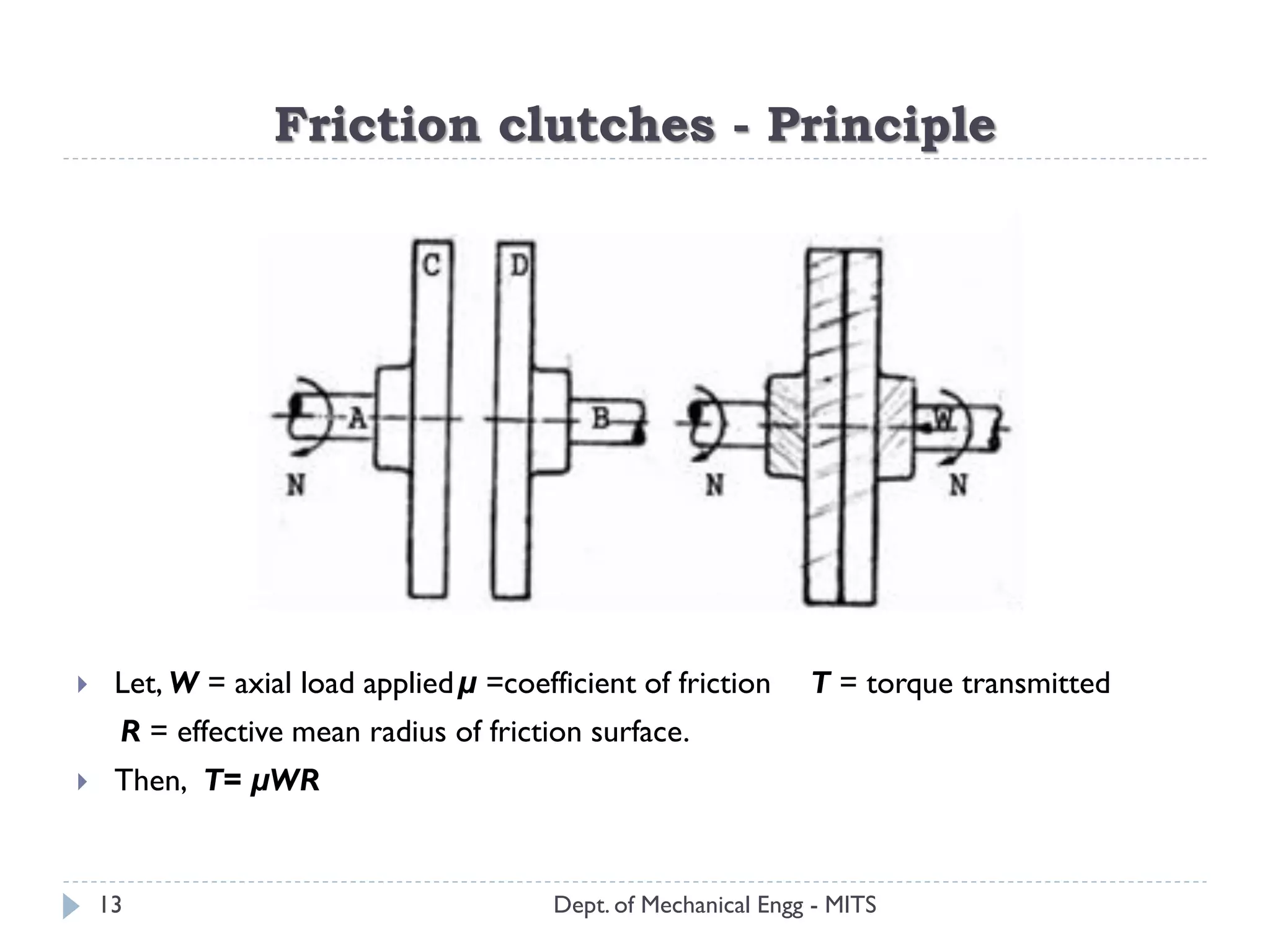
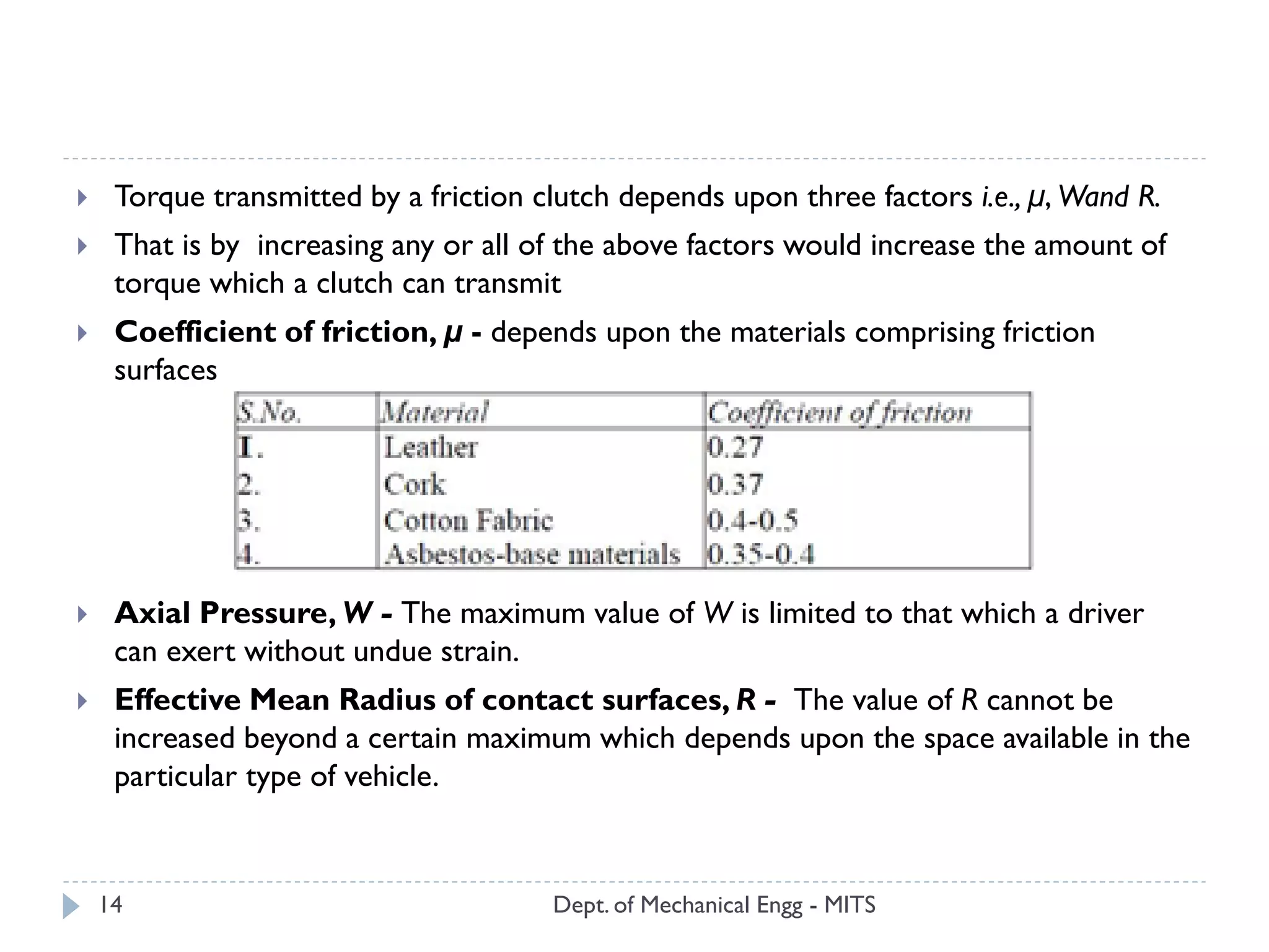
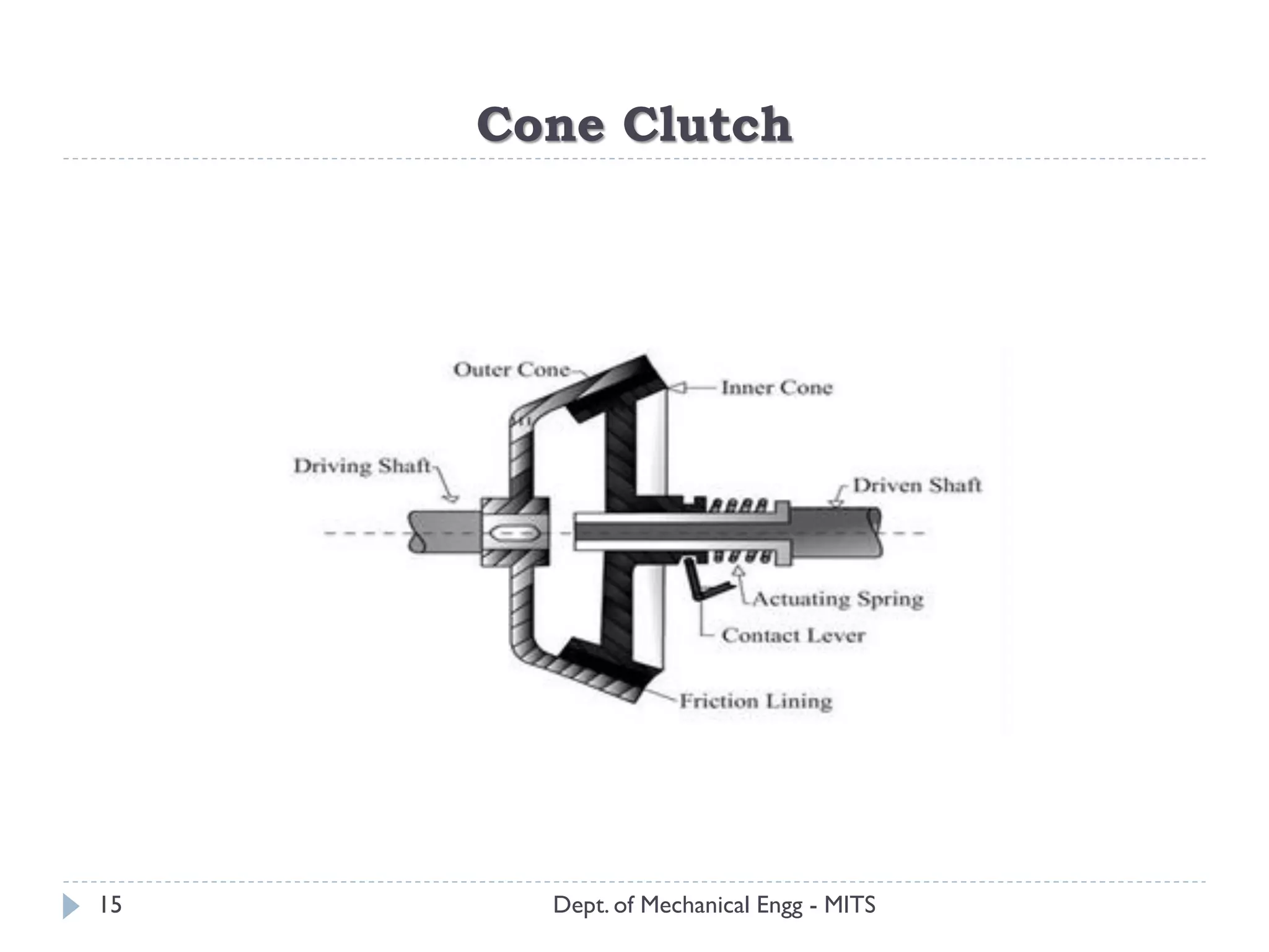
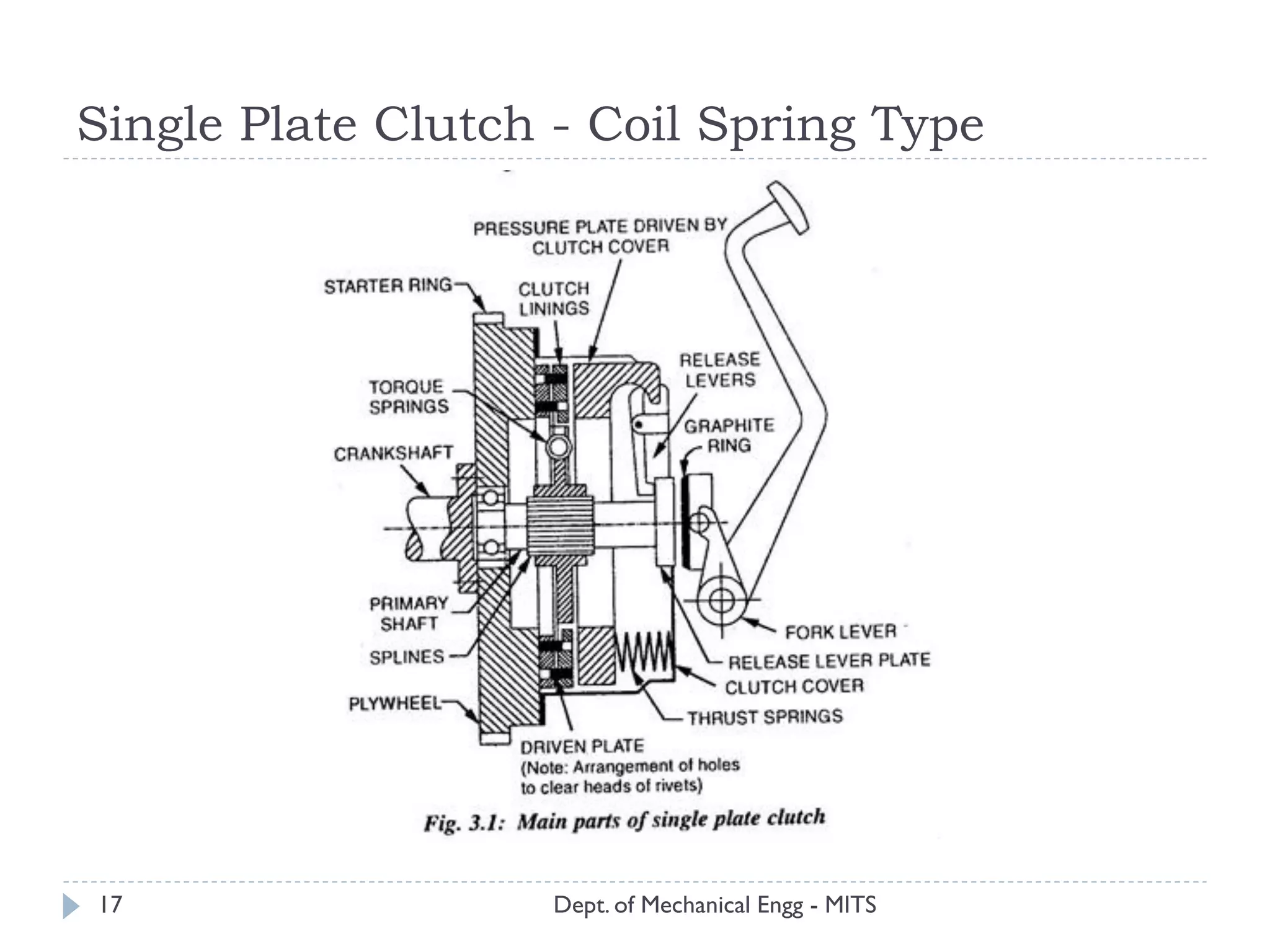
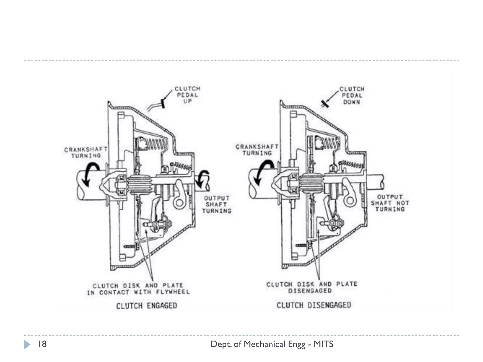
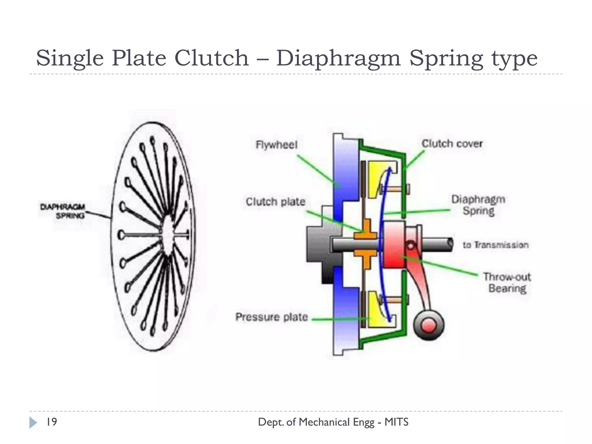
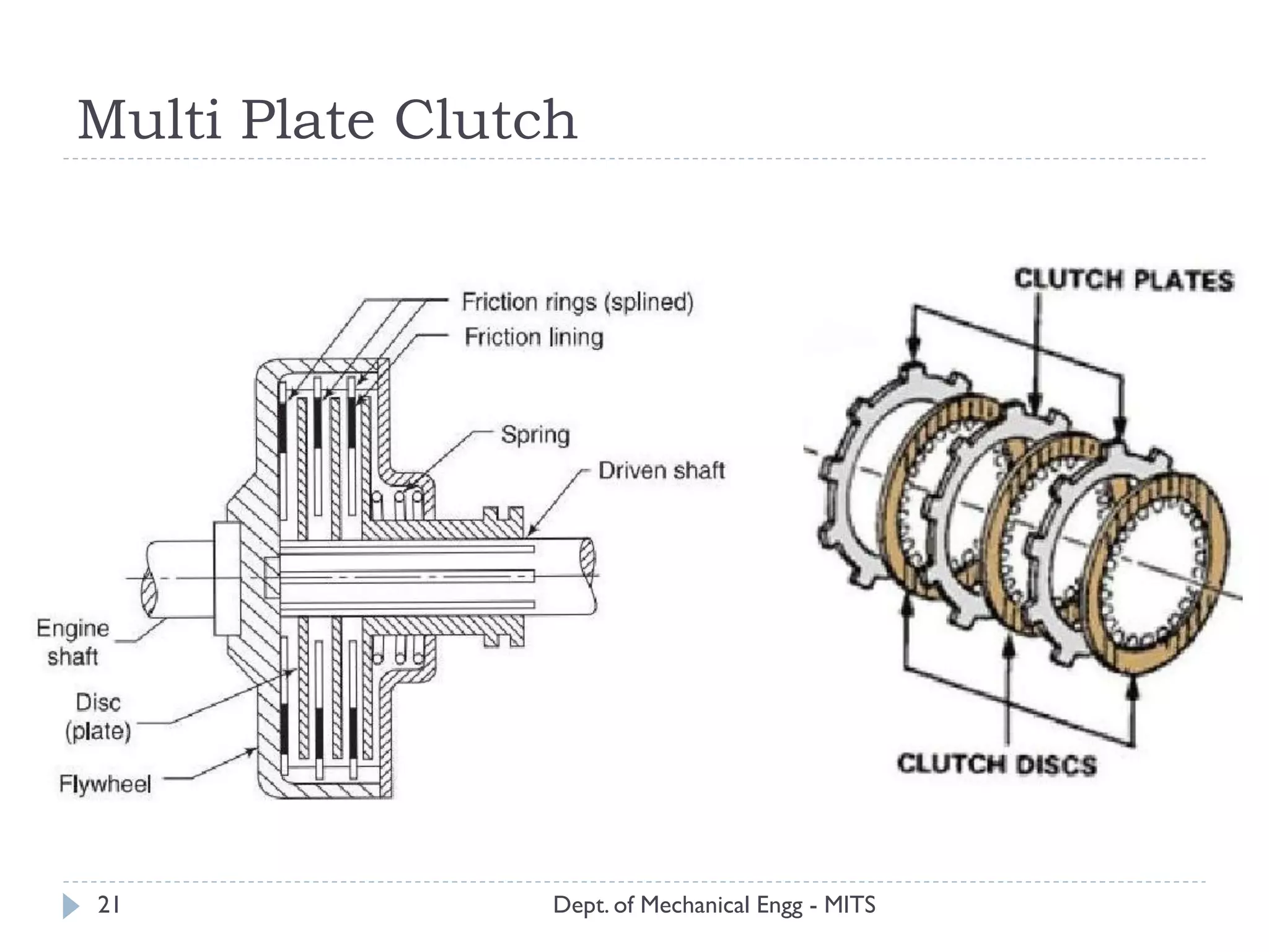
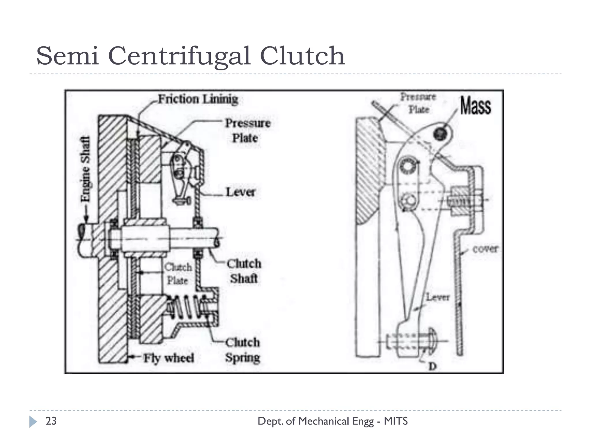
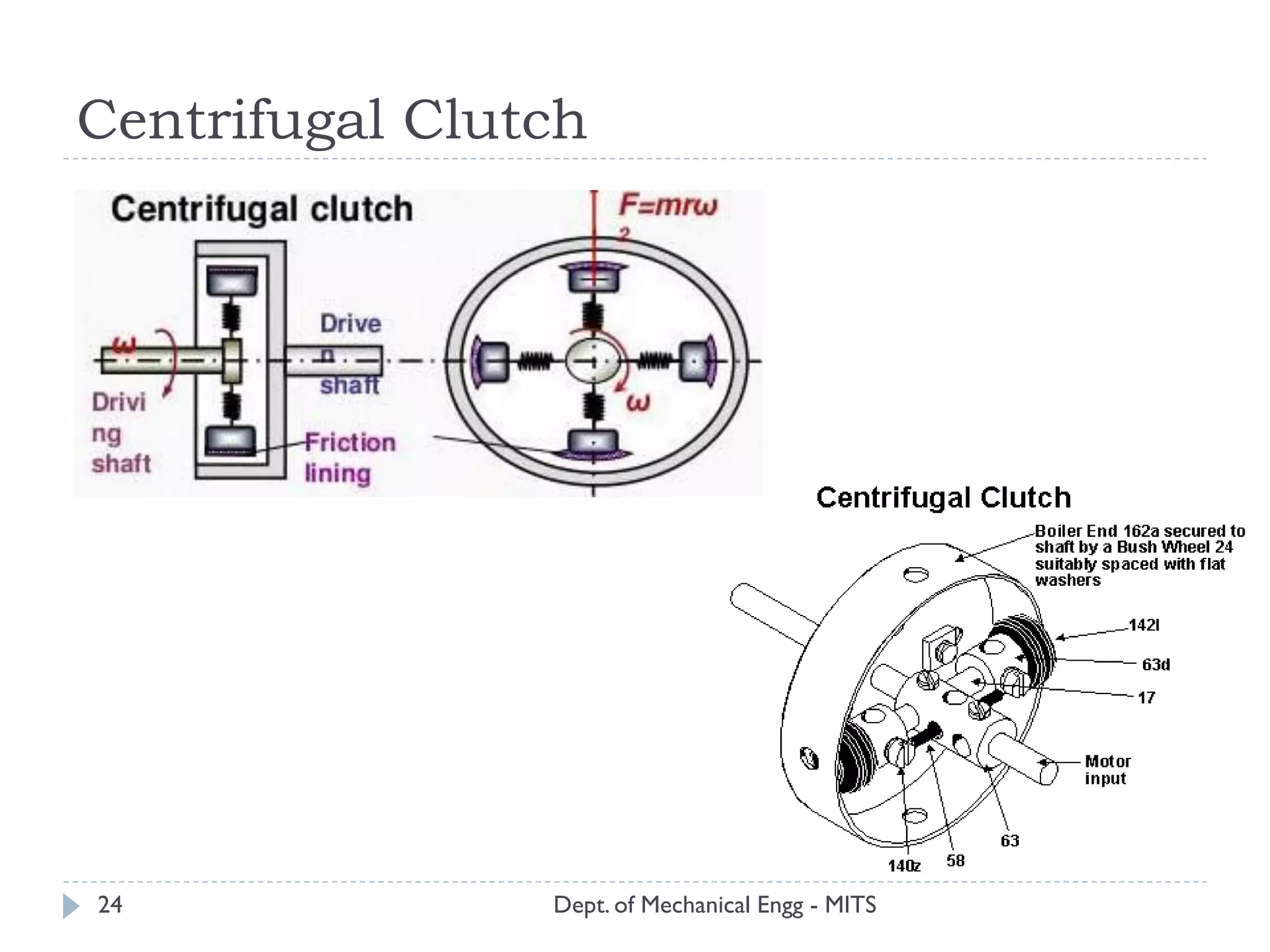
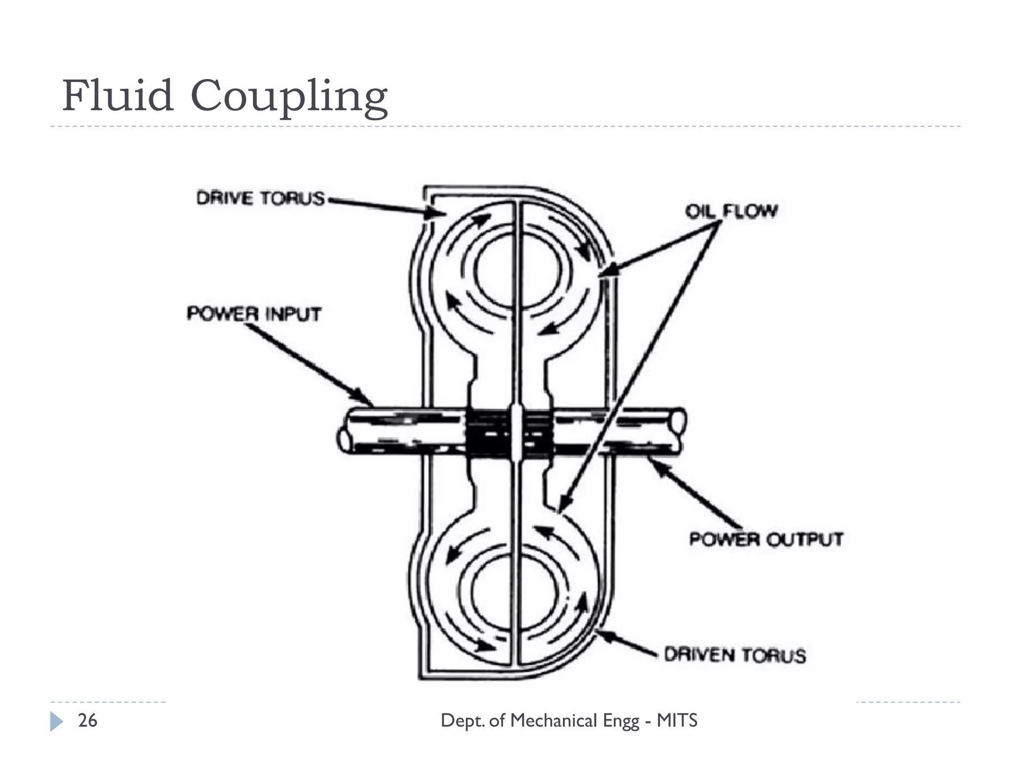
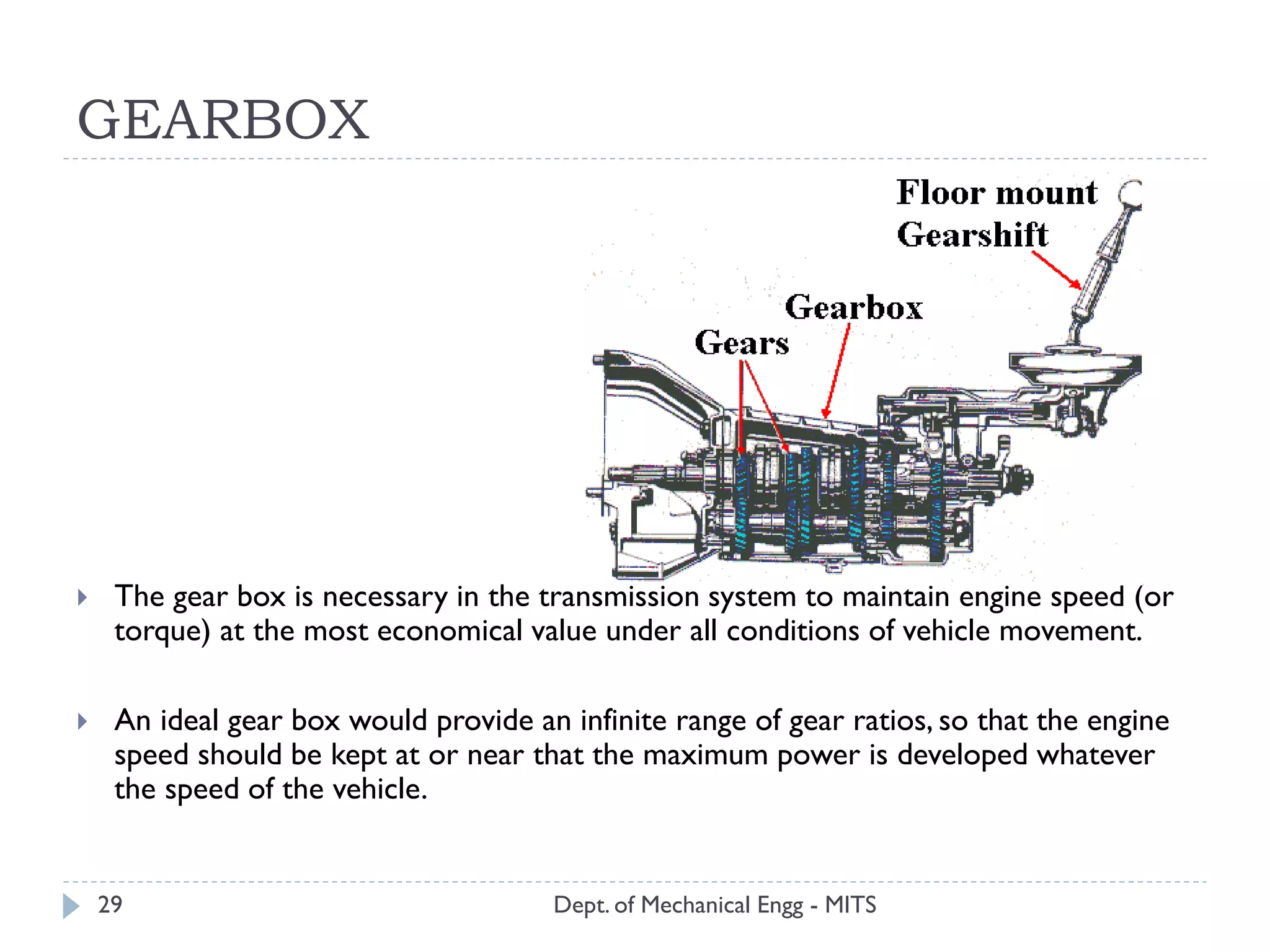
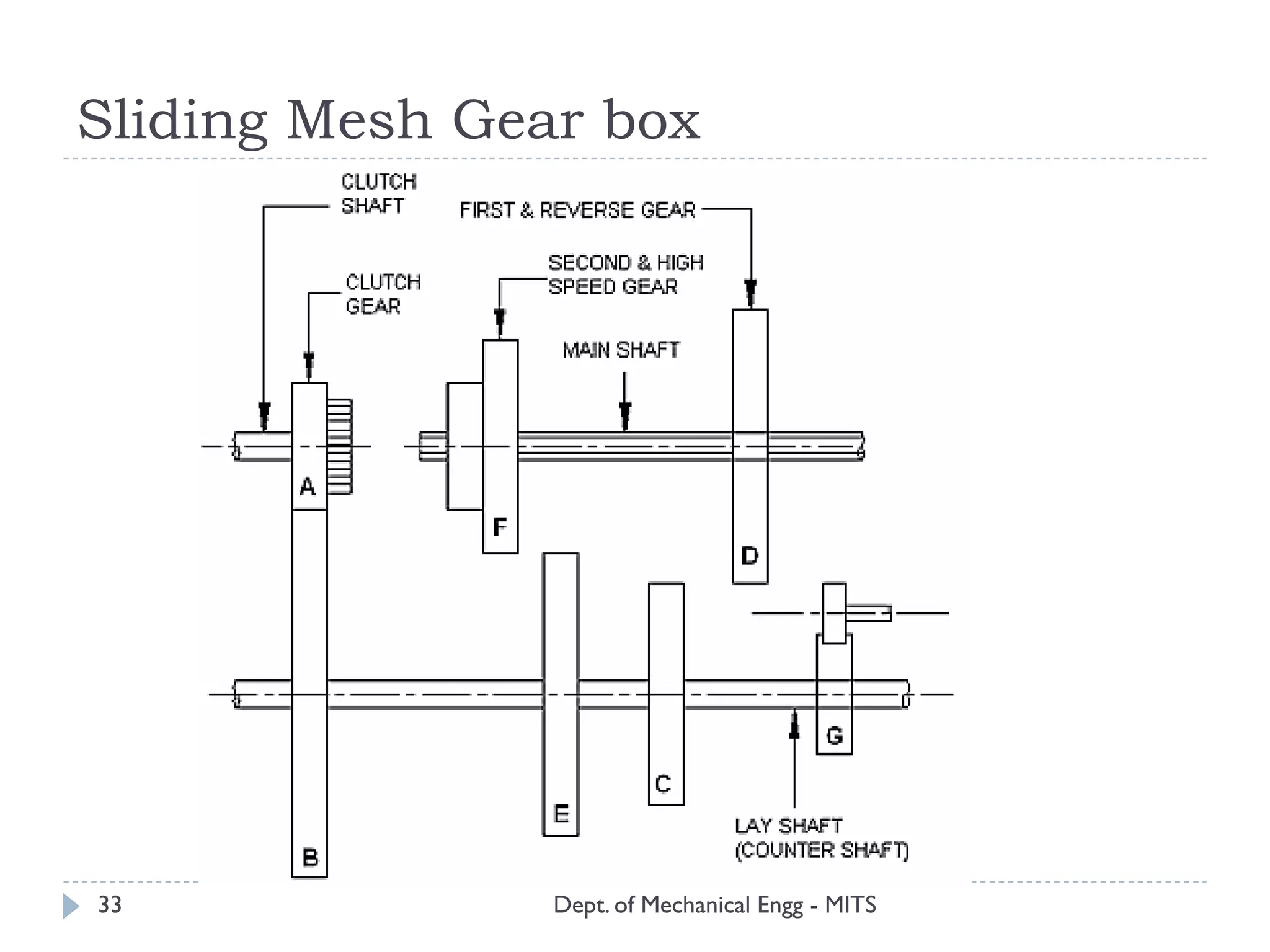
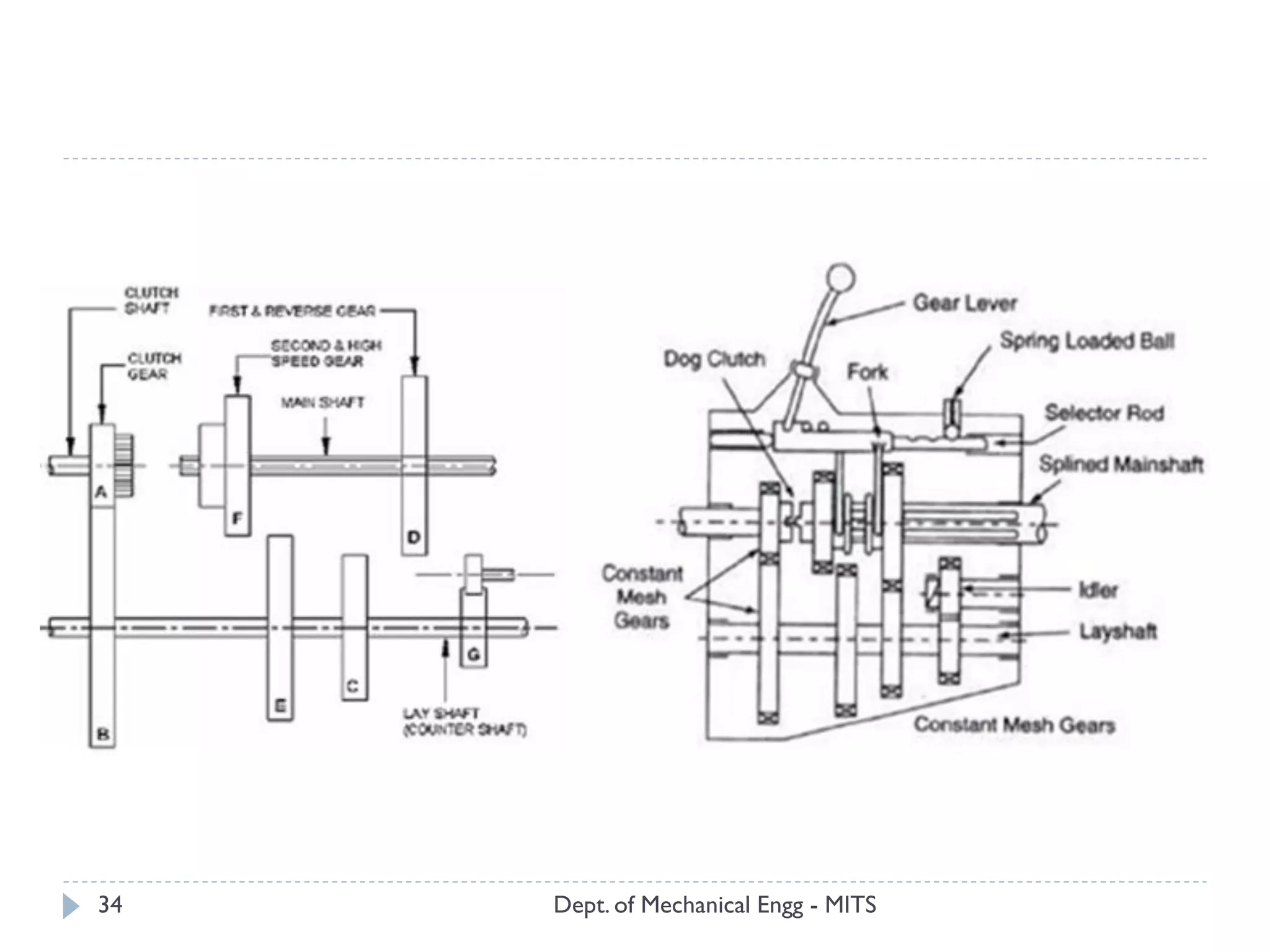
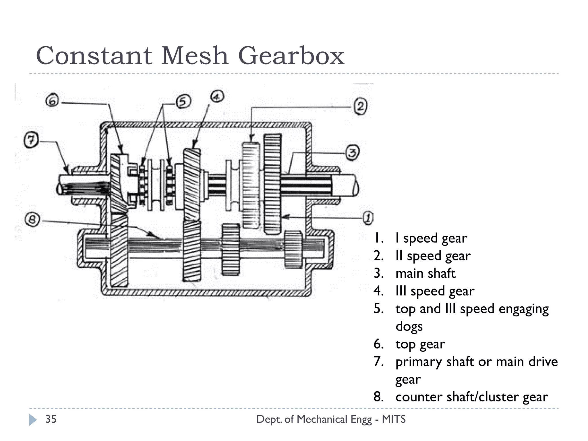
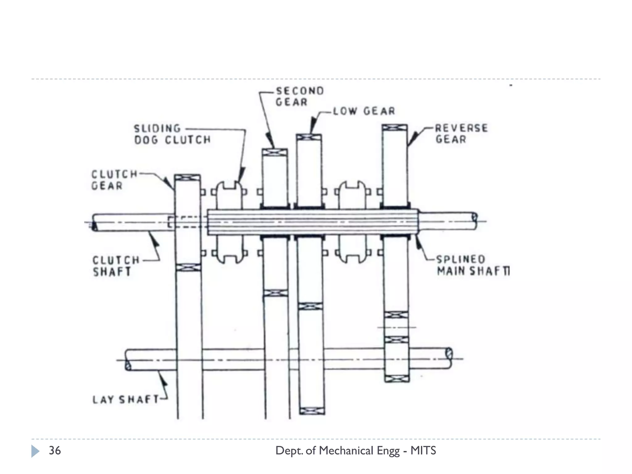
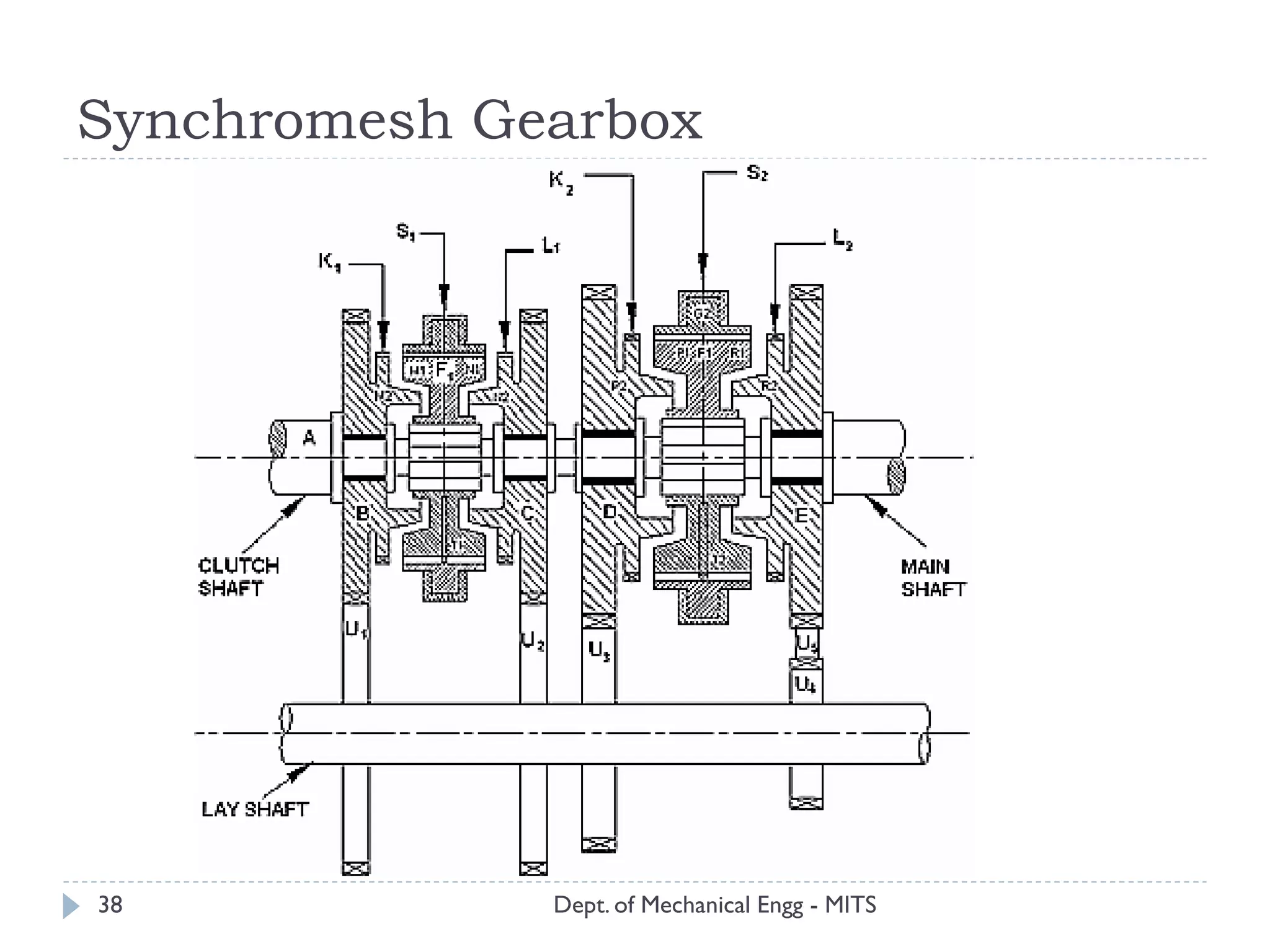
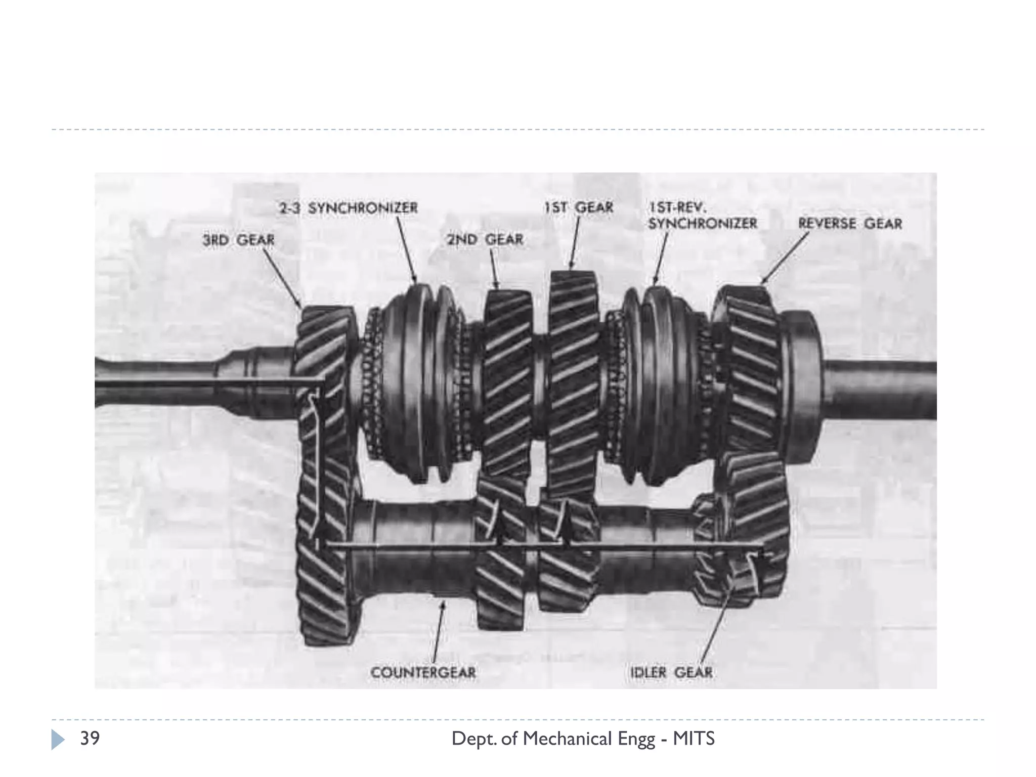
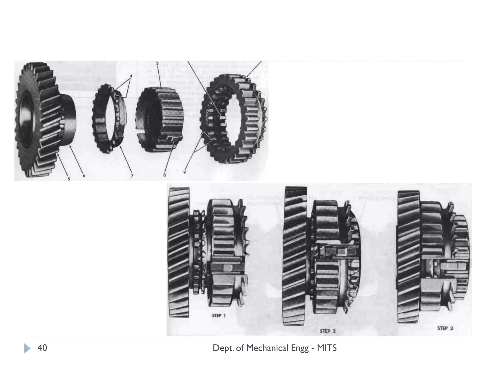
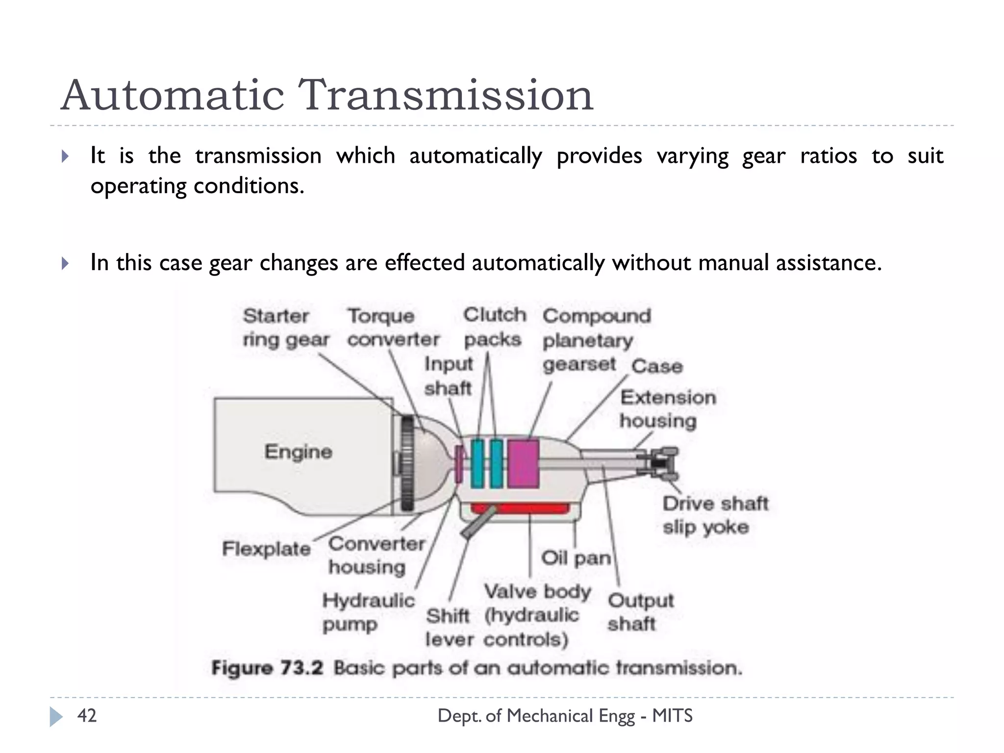
Module II
Transmission System
Presented By
Anoop P
Dept. of Mechanical Engg - MITS1
Transmission System
Dept. of Mechanical Engg - MITS
 The mechanism that transmits the power developed by the engine of the
automobile to the driving wheel is called the transmission system or the power
train.
 It is composed of the clutch, the gear box, propeller shaft, universal joints, rear axle,
wheels and tyres.
 The vehicles which have front wheel drive in addition include a second set of
propeller shafts, universal joints, final drives and differentials for the fronts units.
2
CLUTCH
 A clutch is a mechanism which enables the rotary motion of one shaft to be
transmitted at will to second shaft ,whose axis is coincident with that of first.
 Clutch is located between engine and gear box.
 When the clutch is engaged, the power flows from the engine to the rear wheels
through the transmission system and the vehicle moves .
 When the clutch is disengaged ,the power is not transmitted to the rear wheels
and the vehicle stops, while the engine is still running.
 Clutch is disengaged when
 a) Starting the engine,
 b) Shifting the gears,
 c) Idling the engine
 clutch is engaged only when the vehicle is to move and is kept engaged when the
vehicle is moving.
Dept. of Mechanical Engg - MITS3
Functions
Dept. of Mechanical Engg - MITS
 to permit engagement or disengagement of a gear when the vehicle is stationary
and the engine is running.
 to transmit the engine power to the road wheels smoothly without jerks to the
transmission system while setting the vehicle in motion.
 to permit the engaging of the gears when the vehicle is in motion without damaging
the gear wheels.
4
Characteristics of a good clutch
Dept. of Mechanical Engg - MITS
 It must be simple to operate the clutch.
 Power must be transmitted smoothly.
 Once clutch is engaged, it must transmit power without slipping.
 It must disengage accurately and quickly.
 It must have good heat radiation properties.
 It must be well balanced during rotation.
 It must have long trouble-free life.
 It must be easy to inspect, adjust and repair.
5
Requirements of clutch
Dept. of Mechanical Engg - MITS
 Torque transmission
 Gradual engagement
 Heat dissipation
 Dynamic balancing
 Vibration damping
 Size
 Inertia
 Clutch free pedal play
 Ease of operation
6
Clutch Components
Dept. of Mechanical Engg - MITS
 Friction clutch is used on most automobiles with manual transmission
 It consists of three main parts namely:
 Driving Members
 Driven Members
 Operating Members
7
Dept. of Mechanical Engg - MITS8
Driving member
Dept. of Mechanical Engg - MITS
 It is comprised of flywheel , pressure plate, pressure springs and releasing levers
 Flywheel is the foundation on which the clutch assembly is mounted
 Clutch side is machined smoothly to provide friction surface
 Pressure plate is made of cast iron and is of the same size as of the clutch disc
9
Driven Member
Dept. of Mechanical Engg - MITS
 It has a clutch disc/plate which is gripped between the flywheel and pressure plate
by the action of springs
 It is constructed into two parts
 Outer disc of high quality steel which is covered with friction material
 Inner disc is reinforced and splined hub which engages with the clutch shaft
 Clutch plates are perforated for quick and effective dissipation of heat generated
due to friction surfaces
10
Operating Member
Dept. of Mechanical Engg - MITS
It consists of
 Foot pedal and linkage
 Release or throw out bearing
 Release levers and springs
11
Clutch - Types
Dept. of Mechanical Engg - MITS
Friction clutches
The friction clutches work on the fact that friction is caused when two rotating discs come
into contact with each other
 Cone clutches
 Single plate clutch (coil spring & diaphragm type)
 Multi-plate clutch
 Semi centrifugal clutch
 Centrifugal clutch
Fluid Coupling
Fluid flywheelWorks on the transfer of energy from one rotor to the other by means of fluid
pressure.
12
Friction clutches - Principle
Dept. of Mechanical Engg - MITS
 Let, W = axial load appliedμ =coefficient of friction T = torque transmitted
R = effective mean radius of friction surface.
 Then, T= μWR
13
Dept. of Mechanical Engg - MITS
 Torque transmitted by a friction clutch depends upon three factors i.e., μ, Wand R.
 That is by increasing any or all of the above factors would increase the amount of
torque which a clutch can transmit
 Coefficient of friction, μ - depends upon the materials comprising friction
surfaces
 Axial Pressure, W - The maximum value of W is limited to that which a driver
can exert without undue strain.
 Effective Mean Radius of contact surfaces, R - The value of R cannot be
increased beyond a certain maximum which depends upon the space available in the
particular type of vehicle.
14
Cone Clutch
Dept. of Mechanical Engg - MITS15
Dept. of Mechanical Engg - MITS16
Advantage
 The only advantage of the cone clutch is that the normal force acting on the
contact surfaces in this case is larger than the axial force, as compared to the simple
single plate clutch in which the normal force acting on the contact surfaces is equal
to the axial force.
Disadvantages
 This type of clutch is practically obsolete because of certain inherent disadvantages:
 If the angle of cone is made smaller than about 20° the male cone tends to bind or
join in the female cone and it becomes difficult to disengage the clutch.
 A small amount of wear on the cone surface results in a considerable amount of
the axial movement of the male cone which cannot be tolerated.
Single Plate Clutch - Coil Spring Type
Dept. of Mechanical Engg - MITS17
Dept. of Mechanical Engg - MITS18
Single Plate Clutch – Diaphragm Spring type
Dept. of Mechanical Engg - MITS19
ADVANTAGES
Dept. of Mechanical Engg - MITS20
 It is more compact than other designs.
 It is easier to balance rotationally and is less subjected to unwanted effects due to
centrifugal force at high rotational speeds.
 It gives uniformly distributed pressure on pressure plate.
 It needs no release levers.
 Minimum effort is sufficient to disengage the clutch.
 It provides minimum number of moving components and hence minimum internal
friction is experienced.
 This is very commonly used in cars, light Lorries and mini trucks but is not much
used in heavy vehicles
Multi Plate Clutch
Dept. of Mechanical Engg - MITS21
Dept. of Mechanical Engg - MITS22
Multi-plate clutches are preferred in vehicles:
 If the torque to be transmitted is high.
 Space available is limited
Semi Centrifugal Clutch
Dept. of Mechanical Engg - MITS23
Centrifugal Clutch
Dept. of Mechanical Engg - MITS24
Dept. of Mechanical Engg - MITS25
Advantages
 This type of mechanical clutch is automatic, so no kind of control mechanism is
necessary.
 Centrifugal clutch is fairly cheap compare to normal type on clutch.
 It prevents engine from stalling in other words minimizes engine braking force.
Disadvantages
 This clutch is not appropriate for transferring significant torque or power because
they can slip if loaded heavily.
 Sometimes the centrifugal clutch do not engage or disengage reliably and therefore
can cause a safety hazard.
Fluid Coupling
Dept. of Mechanical Engg - MITS26
Dept. of Mechanical Engg - MITS27
 A fluid coupling or hydraulic coupling is a hydrodynamic device used to
transmit rotating mechanical power.
 It has been used in automobile transmissions as an alternative to a mechanical
clutch.
 It has widespread application in marine and industrial machine drives, where
variable speed operation and controlled start-up without shock loading of the
power transmission system is essential.
Advantages
Dept. of Mechanical Engg - MITS28
 It provides acceleration pedal control to effect automatic disengagement of drive to
gearbox at a predetermined speed.
 Vibrations from engine side are not transmitted to wheels and similarly shock loads
from transmission side will not be transmitted to engine.
 The engine will not stall if it is overloaded.
 No wear on moving parts and no adjustments to be made.
 No jerk on transmission when gear engages.
 Vehicle can be stopped in gear and move off by pressing acceleration only.
 There is no direct firm connection between engines and wheels. So when engine is
overloaded, it will not stop. But it results in slip within coupling.
 Unlike friction clutch, slip within coupling does not cause damage within working
components.
 In case of FC, engine is not forced to operate at very low speeds when it is
overloaded.
 No wear is experienced on impeller or turbine blades.
GEARBOX
Dept. of Mechanical Engg - MITS29
 The gear box is necessary in the transmission system to maintain engine speed (or
torque) at the most economical value under all conditions of vehicle movement.
 An ideal gear box would provide an infinite range of gear ratios, so that the engine
speed should be kept at or near that the maximum power is developed whatever
the speed of the vehicle.
Functions
Dept. of Mechanical Engg - MITS30
 Helps to select torque ratio between the engine and wheels to be varied for rapid
acceleration and for climbing gradients.
 It provides means of reversal of vehicle motion.
 Transmission can be disconnected from engine by neutral position at gear box
Types of gearbox
Dept. of Mechanical Engg - MITS31
 Selective type gear boxes
 (i)Sliding mesh gear box
 (ii)Constant mesh gear box
 (iii)Synchromesh gear box
 Progressive type gear box
 Epi-cyclic type gear box
Selective type gear boxes
Dept. of Mechanical Engg - MITS32
 It is the transmission in which any speed may be selected from the neutral position.
 In this type of transmission neutral position has to be obtained before selecting any
forward or reverse gear.
Sliding Mesh Gear box
Dept. of Mechanical Engg - MITS33
Dept. of Mechanical Engg - MITS34
Constant Mesh Gearbox
Dept. of Mechanical Engg - MITS35
1. I speed gear
2. II speed gear
3. main shaft
4. III speed gear
5. top and III speed engaging
dogs
6. top gear
7. primary shaft or main drive
gear
8. counter shaft/cluster gear
Dept. of Mechanical Engg - MITS36
Dept. of Mechanical Engg - MITS37
Advantages
 Compared to the sliding mesh type, the constant mesh gear box has the following
advantages:
 As the gears have to remain always in mesh, it is no longer necessary to use straight
spur gears. Instead, helical gears are used which are quieter running.
 Wear of dog teeth on account of engaging and disengaging is reduced because here
all the teeth of the dog clutches are involved compared to only two or three teeth
in the case of sliding gears.
Disadvantages
 Dog clutch engagements are bit noisy
 In constant mesh gear box the driver has to undergo double-declutching while
shifting gears.
Synchromesh Gearbox
Dept. of Mechanical Engg - MITS38
Dept. of Mechanical Engg - MITS39
Dept. of Mechanical Engg - MITS40
Advantage
Dept. of Mechanical Engg - MITS41
 The synchromesh type of transmission has the big advantage of allowing smooth
type and quick shifting of gears without danger of damaging the gears and without
necessity for double clutching.
 The synchromesh gear box is considered the most advanced and has been adopted
in most cars.
Automatic Transmission
Dept. of Mechanical Engg - MITS42
 It is the transmission which automatically provides varying gear ratios to suit
operating conditions.
 In this case gear changes are effected automatically without manual assistance.
Components
Dept. of Mechanical Engg - MITS43
Main Components of AutomaticTransmission System
 Torque Converter.
 Gearbox of planetary type with friction brake bands and multiple disc clutch
operated by hydraulic system.
 Hydraulic Control SystemThis system has a source of hydraulic pressure servo
units and control valves.
ADVANTAGES
Dept. of Mechanical Engg - MITS44
 Ease of control, i.e. it relieves the driver from fatigue due to the elimination of
clutch and gear controls.
 Smooth operation.
 Numerous numbers of gear ratios are available.
 Quick change of gear ratios effected automatically.
 Minimum interruption of power during gear shifts.
Disadvantages
Dept. of Mechanical Engg - MITS45
 High cost.
 Complicated design.
 Possibility for oil leakage.
Torque Convertor
Dept. of Mechanical Engg - MITS46
Dept. of Mechanical Engg - MITS47
 Most cars with automatic transmission use a form of fluid drive known as torque
converter
 As the name implies, it converts the torque or tuning effort of engine into higher
torque needed by cars at low road speed.
 An increase in torque has same effect as changing to a lower gear; so a torque
converter is also a gear reducer, acting like an extra set of gears before engine drive
reaches gear box.
Dept. of Mechanical Engg - MITS48
Dept. of Mechanical Engg - MITS49
A torque converter also does following jobs:
 It serves as automatic clutch which transmits engine torque to the transmission
input shaft.
 Absorbs torsional vibration of engine.
 Acts as a flywheel and smoothens out engine rotation.
 Drives oil pump.
Dept. of Mechanical Engg - MITS50
Epi-cyclic (Planetary) Gear Box
Dept. of Mechanical Engg - MITS51
Dept. of Mechanical Engg - MITS52
Dept. of Mechanical Engg - MITS53
Dept. of Mechanical Engg - MITS54
 The term planetary gear system comes from its similarity with the solar system
 i.e. like planets revolving round the sun
 Gearing provides different torque ratios by locking of 3 basic components
 Sun gear
 Planet gear
 Annular ring
Dept. of Mechanical Engg - MITS55
 Gear reduction
 Sun gear is held stationary
 Ring gear drives the planet carrier
 Ring gear is locked
 Planet carrier drives the sun gear
 Direct drive
 Locking together the sun and planet gears
 The entire planetary set rotates as a single unit
 Reverse
 Locking pinion carrier/arm
 Sun gear is the driving member and ring gear the driven
 Here planet gears are free to rotate about their own axes
Dept. of Mechanical Engg - MITS56
 Neutral
 None of the driving members is coupled to planetary gear set
 Overdrive
 Sun gear is held stationary
 Planet carrier is the driving unit and the ring gear is driven
 Ring gear is locked
 The planet carrier is the driving unit and sun gear is the driven unit
OVERDRIVE
Dept. of Mechanical Engg - MITS57
Dept. of Mechanical Engg - MITS58
 Overdrive is a device interposed between the transmission (gear box) and
propeller shaft to permit the propeller shaft to turn faster than or-over drive the
transmission main shaft.
 It is so called because it provides a speed ratio over that of the high speed ratio.
 The overdrive permits the engine to operate only about 70 percent of the
propeller shaft speed, when the vehicle is operating in the high speed ranges.
 Overdrive is usually, employed supplementary to conventional transmission.
 It is bolted to the rear of the transmission between the transmission and propeller
shaft
 A slightly higher rear-axle gear ratio is employed with an overdrive than without
one.
Dept. of Mechanical Engg - MITS59
ADVANTAGES
 This device permits the engine to operate at only about 70% of the propeller shaft speed
when the car is operating in the higher speed ranges. i.e., over drive engine speed about 30%.
 Because the engine is not required to turn over fast at high car speed, the use of over drive
reduces engine wear and vibration and saves gasoline.
 Usually a slightly higher rear –axle gear ratio is employed with an over –drive then without
one.
DRAWBACKS
 In descending long steep hills where the braking effect of the engine would be lost due to slip
 The driving force available at the wheels is less in case of vehicles with over-drive.
Freewheel (one-way clutch)
Dept. of Mechanical Engg - MITS60
Dept. of Mechanical Engg - MITS61
 A freewheel or overrunning clutch is a device in a transmission that disengages the
driveshaft from the driven shaft when the driven shaft rotates faster than the
driveshaft.
 An overdrive is sometimes mistakenly called a freewheel.
 The condition of a driven shaft spinning faster than its driveshaft exists in most
bicycles when the rider holds his or her feet still, no longer pushing the pedals. In a
fixed-gear bicycle, without a freewheel, the rear wheel would drive the pedals
around.
 An analogous condition exists in an automobile with a manual
transmission going downhill or any situation where the driver takes his
or her foot off the gas pedal, closing the throttle; the wheels want to
drive the engine, possibly at a higher RPM.
Hydraulic control system
Dept. of Mechanical Engg - MITS62
 The hydraulic control system consists of an oil pan (which acts as fluid reservoir),
 pump (which builds oil pressure)
 Various valves (controls oil path to lock and unlock various clutches and band
brakes)
Dept. of Mechanical Engg - MITS63
Dept. of Mechanical Engg - MITS64
Manual shift valve
 This valve is located in the hydraulic control unit, and actuated by drivers selector
unit.
 It determines which gear ratio to be selected.
 The position of the selector lever can be used to vary the working pressure of shift
valves.
 Operation of the lever moves the valve and uncovers the fluid port that supplies
hydraulic pressure to clutches and brake bands to obtain the desired gear position.
 Speed Sensing
 Load sensing
Propeller shaft
Dept. of Mechanical Engg - MITS65
 The propeller shaft connects the transmission main or the output shaft of the gear
box to the differential of the rear axle.
 The propeller shaft transmits the power from gear box to rear axle with the help
of universal joints.
 Universal joints are fitted on both the ends of the shaft.
Dept. of Mechanical Engg - MITS66
 It propels the vehicle forward, so called propeller shaft
 A Propeller Shaft connects a gearbox to the Differential.
 It is strong enough to handle maximum low gear torque
 It is provided with two Universal-joints to maintain constant velocity and
positioning of differential at different plane.
 It is provided with a slip joint to take care of the change in length.
 Shaft diameter and its thickness decide the torque carrying capacity and angle of
operation.
 For long transmissions split type propeller shafts with central support are used.
Universal Joint
Dept. of Mechanical Engg - MITS67
Dept. of Mechanical Engg - MITS68
 A universal joint allows driving torque to be carried through two shafts that are at
an angle with each other.
 A simple universal joint consist twoY- shaped yoke, one on the driving shaft and
other on the driven shaft.
 The four arms of spider are assembled in needle bearings in the two yokes.The
driving shaft and yoke force the spider to rotate.
 The other two trunnions of the spider then cause the driven yoke to rotate.
 When the two shafts are at an angle with each other, the needle bearings permit
the yokes to swing around on the trunnions with each revolution.
 A simple universal joint does not transmit the motion uniformly when the shafts
are operating an angle. Because of this, two universal joints are used in a vehicle,
one between the gear box and the propeller shaft and other between the propeller
shaft and the differential pinion shaft.
Slip joint
Dept. of Mechanical Engg - MITS69
 Slip joint is attached to the driven yoke in order the increase or decrease the length
of propeller shaft.
 It has outside splines on the shaft and matching internal splines in a mating
hollow shaft or yoke.
 When assembled the splines cause the shafts to rotate together while they can
move back and forth.This changes the length of propeller shaft.
Final drive/ Final reduction
Dept. of Mechanical Engg - MITS70
Dept. of Mechanical Engg - MITS71
 Final drive is a part of the transmission between the propeller shaft and the
differential gear assembly.
 It consists of a combination of large sized crown wheel and a bevel pinion.
 It serves the following functions:
 Transmit the drive from propeller shaft through 900
 Enables the driving wheels to rotate at different speeds
 Reduce the drive line speed from that of engine to the drive wheels
 Final drive in case of a motorcycle is a chain and sprocket.
Dept. of Mechanical Engg - MITS72
Differential Assembly
Dept. of Mechanical Engg - MITS73
Dept. of Mechanical Engg - MITS74
 Differential is the mechanism by means of which outer wheel runs faster than the
inner wheels while taking a turn or moving over upheaval road.
 Differential is a part of the inner axle housing assembly, which includes the
differential, rear axles, wheels and bearings.
 The differential consists of a system of gears arranged in such a way that connects
'the propeller shaft with the rear axles.
 The purpose of the differential is to provide the relative movement to the two rear
wheels, while the vehicle is taking a turn.
 The torque transmitted to each wheel is, however, always equal. Differentials are
used in rear drive axle of front-engine, rear-wheel drive vehicles.
 Differentials are also used in the Trans axles on front-engine, front-wheel drive
wheels.
 Also, four-wheel drive vehicles have differential at both the front and rear wheels. In
addition, some four-wheel-drive vehicles have a third differential in the transfer case.
Transaxle
Dept. of Mechanical Engg - MITS75
 In the automotive field, a transaxle is a major mechanical component that combines
the functionality of the transmission, the differential and associated components of
the driven axle into one integrated assembly.
 Transaxles are used almost in all automobile configurations that have the engine
placed at the same end (transversely) of the car as the driven wheels:
 the front-engine, front-wheel drive layout, rear-engine, rear-wheel drive layout
and rear mid-engine, rear-wheel drive layout arrangements.
FOUR WHEEL DRIVE (4WD or 4X4)
Dept. of Mechanical Engg - MITS76
Axle
Dept. of Mechanical Engg - MITS77
 An axle is a central shaft for a rotating wheel or gear.
 On wheeled vehicles, the axle may be fixed to the wheels, rotating with them, or
fixed to the vehicle, with the wheels rotating around the axle.
 In the former case, bearings or bushings are provided at the mounting points where
the axle is supported.
 In the latter case, a bearing or bushing sits inside a central hole in the wheel to
allow the wheel or gear to rotate around the axle.
 Sometimes, especially on bicycles, the latter type axle is referred to as a spindle.
Dead axle (lazy axle)
Dept. of Mechanical Engg - MITS78
 Dead axle, also called lazy axle, is not part of the drive train but is instead free-
rotating.
 The rear axle of a front-wheel drive car is usually a dead axle.
 Many trucks and trailers use dead axles for strictly load-bearing purposes.
 A dead axle located immediately in front of a drive axle is called a pusher axle.
 A tag axle is a dead axle situated behind a drive axle.
Live Axle
Dept. of Mechanical Engg - MITS79
 A live axle is a type of beam axle in which the shaft transmits power to the wheels.
 The drawbacks are that it does not allow each wheel to move independently in
response to bumps.
 In case of vehicles having common axle for drive and steering will be employed with
constant velocity joints, so that no transfer losses are possible while steering.
Forces and torque on rear axle
Dept. of Mechanical Engg - MITS80
 Weight of the body
 Rear axle behaves like a beam supported at the ends and loaded at two points.
 The load coming on the axle is due to the weight of the body being transmitted
through the suspension springs.
 Weight causes shear force and bending on the wheels.
Dept. of Mechanical Engg - MITS81
 Driving thrust
 Torque produced by the engine causes the thrust on the wheels, which is
responsible for the forward motion of the vehicle.
 The drive force from the wheels is transmitted to the body or chassis by means of
leaf springs or Radius rods (strut rod / thrust members).
 These members are in longitudinal direction connecting axle casing and the body.
Dept. of Mechanical Engg - MITS82
 Torque reaction
 If the road wheels are prevented from rotation, with propeller shaft rotating it is
seen that the bevel pinion tend to roll around the crown gear of the differential.
 This tendency is also present when the vehicle is running so that bevel pinion
always tends to climb round the crown wheel.
 Thus there is a force on axle casing to rotate.This is called torque reaction.
Dept. of Mechanical Engg - MITS83
 Side thrust
 Side thrust comes mainly when the vehicle is taking a turn or when the vehicle is
moving along an laterally inclined surface.
 The side thrust coming on to the axle can be taken by Panhard rod.
Types of Rear Axle Drives
Dept. of Mechanical Engg - MITS84
Hotch Kiss Drive
Dept. of Mechanical Engg - MITS85
 Simplest and most widely used rear axle drive.
Dept. of Mechanical Engg - MITS86
 Propeller shaft with two universal joints and a sliding joint.
 The spring is fixed rigidly in the middle onto the frame.The drive torque is
transmitted through the front half of the springs.
 The front end of the leaf suspension is rigidly fixed onto the frame while the rear is
connected via a shackle.
 Two universal joints are used to avoid the bending of the propeller shaft due to the
torque reaction.
 Sliding joint is provided to accommodate for the variation of the length in the
transmission shaft.
Advantages
Dept. of Mechanical Engg - MITS87
 Torque reaction, driving thrust and side thrust are taken up by the leaf spring and
universal joints
 Varying propeller shaft length can be accommodated without any inclination
 Provides comfortable ride
Torque Tube Drive
Dept. of Mechanical Engg - MITS88
Dept. of Mechanical Engg - MITS89
 Torque reaction, Braking torque and drive thrust are taken byTorque tube.
 The suspension springs are takes only the side thrust and body weight.
 One end of the torque tube is attached to the axle casing while the other end is
spherical and fits into the cup on the frame.
 The torque tube encloses the propeller shaft.
 Torque tube takes the torque reaction and centre line of the bevel pinion shaft always
passes through the centre of the spherical cup.
 Single universal joint is used in the transmission drive because the universal joint is
situated exactly at the centre of the spherical cup.
 No sliding joint is provided since the pinion shaft and the propeller shaft moves same
center ( spherical cup).
Radius rods
Dept. of Mechanical Engg - MITS90
 The side way forces are transmitted to the axle from the frame normally by the
springs.
 The coil or torsion springs can’t be used with flexibility
 In such cases a transverse radius rod is provided parallel to the wheel axis, which is
pivoted at one end to the axle and other end to the frame
 The ball and socket joints are used at the end of the rods to provide relative
motion
Classification of Rear Axle
Dept. of Mechanical Engg - MITS91
Dept. of Mechanical Engg - MITS92
 According to design of Axle Casing
Dept. of Mechanical Engg - MITS93
 According to the method of supporting
 Fully Floating Axle
Dept. of Mechanical Engg - MITS94
 This is used in heavy vehicles
 Axle carries only driving torque
 Vehicle weight and end thrust aren’t carried by the axle
 Wheels and the axle casing takes care of the vehicle weight
 Axle is relieved from all strains due to load of vehicle and end thrust, hence its duty
is only to transmit rotary motion to the wheels
 Also we can remove the axle shaft without disturbing the axle hub and wheel
Dept. of Mechanical Engg - MITS95
 Semi Floating Axle
 In this type of axle, whole of the load of the rear portion of the vehicle, the end
thrust and the driving torque is carried by the axle.
 The vehicle load is transmitted to each of the half shafts through axle casing and the
bearings.
 The wheel hub is rigidly fixed to the outer end of the axle shaft.
 For replacement of the axle shaft, the vehicle is jacked up.The wheel, the drum and
the bearing retainer plate must be removed in order to remove the axle shaft.
Dept. of Mechanical Engg - MITS96
 Three Quarter floating Axle
 This design is a compromise between the fully floating axle and the semi-floating
type.
 The bearing is carried on the axle casing, the hub is rigidly fixed to the outer end of
the axle shaft.
 The axle shaft is not supporting any weight but will have to withstand the end
thrusts besides transmitting the driving torque.
 Due to the reason that three quarter floating axle has only one bearing at the outer
end, but even then it takes some bending stresses, it, therefore, is not resembling
the fully floating type.

Automobile module ii

  • 1.
    Module II Transmission System PresentedBy Anoop P Dept. of Mechanical Engg - MITS1
  • 2.
    Transmission System Dept. ofMechanical Engg - MITS  The mechanism that transmits the power developed by the engine of the automobile to the driving wheel is called the transmission system or the power train.  It is composed of the clutch, the gear box, propeller shaft, universal joints, rear axle, wheels and tyres.  The vehicles which have front wheel drive in addition include a second set of propeller shafts, universal joints, final drives and differentials for the fronts units. 2
  • 3.
    CLUTCH  A clutchis a mechanism which enables the rotary motion of one shaft to be transmitted at will to second shaft ,whose axis is coincident with that of first.  Clutch is located between engine and gear box.  When the clutch is engaged, the power flows from the engine to the rear wheels through the transmission system and the vehicle moves .  When the clutch is disengaged ,the power is not transmitted to the rear wheels and the vehicle stops, while the engine is still running.  Clutch is disengaged when  a) Starting the engine,  b) Shifting the gears,  c) Idling the engine  clutch is engaged only when the vehicle is to move and is kept engaged when the vehicle is moving. Dept. of Mechanical Engg - MITS3
  • 4.
    Functions Dept. of MechanicalEngg - MITS  to permit engagement or disengagement of a gear when the vehicle is stationary and the engine is running.  to transmit the engine power to the road wheels smoothly without jerks to the transmission system while setting the vehicle in motion.  to permit the engaging of the gears when the vehicle is in motion without damaging the gear wheels. 4
  • 5.
    Characteristics of agood clutch Dept. of Mechanical Engg - MITS  It must be simple to operate the clutch.  Power must be transmitted smoothly.  Once clutch is engaged, it must transmit power without slipping.  It must disengage accurately and quickly.  It must have good heat radiation properties.  It must be well balanced during rotation.  It must have long trouble-free life.  It must be easy to inspect, adjust and repair. 5
  • 6.
    Requirements of clutch Dept.of Mechanical Engg - MITS  Torque transmission  Gradual engagement  Heat dissipation  Dynamic balancing  Vibration damping  Size  Inertia  Clutch free pedal play  Ease of operation 6
  • 7.
    Clutch Components Dept. ofMechanical Engg - MITS  Friction clutch is used on most automobiles with manual transmission  It consists of three main parts namely:  Driving Members  Driven Members  Operating Members 7
  • 8.
    Dept. of MechanicalEngg - MITS8
  • 9.
    Driving member Dept. ofMechanical Engg - MITS  It is comprised of flywheel , pressure plate, pressure springs and releasing levers  Flywheel is the foundation on which the clutch assembly is mounted  Clutch side is machined smoothly to provide friction surface  Pressure plate is made of cast iron and is of the same size as of the clutch disc 9
  • 10.
    Driven Member Dept. ofMechanical Engg - MITS  It has a clutch disc/plate which is gripped between the flywheel and pressure plate by the action of springs  It is constructed into two parts  Outer disc of high quality steel which is covered with friction material  Inner disc is reinforced and splined hub which engages with the clutch shaft  Clutch plates are perforated for quick and effective dissipation of heat generated due to friction surfaces 10
  • 11.
    Operating Member Dept. ofMechanical Engg - MITS It consists of  Foot pedal and linkage  Release or throw out bearing  Release levers and springs 11
  • 12.
    Clutch - Types Dept.of Mechanical Engg - MITS Friction clutches The friction clutches work on the fact that friction is caused when two rotating discs come into contact with each other  Cone clutches  Single plate clutch (coil spring & diaphragm type)  Multi-plate clutch  Semi centrifugal clutch  Centrifugal clutch Fluid Coupling Fluid flywheelWorks on the transfer of energy from one rotor to the other by means of fluid pressure. 12
  • 13.
    Friction clutches -Principle Dept. of Mechanical Engg - MITS  Let, W = axial load appliedμ =coefficient of friction T = torque transmitted R = effective mean radius of friction surface.  Then, T= μWR 13
  • 14.
    Dept. of MechanicalEngg - MITS  Torque transmitted by a friction clutch depends upon three factors i.e., μ, Wand R.  That is by increasing any or all of the above factors would increase the amount of torque which a clutch can transmit  Coefficient of friction, μ - depends upon the materials comprising friction surfaces  Axial Pressure, W - The maximum value of W is limited to that which a driver can exert without undue strain.  Effective Mean Radius of contact surfaces, R - The value of R cannot be increased beyond a certain maximum which depends upon the space available in the particular type of vehicle. 14
  • 15.
    Cone Clutch Dept. ofMechanical Engg - MITS15
  • 16.
    Dept. of MechanicalEngg - MITS16 Advantage  The only advantage of the cone clutch is that the normal force acting on the contact surfaces in this case is larger than the axial force, as compared to the simple single plate clutch in which the normal force acting on the contact surfaces is equal to the axial force. Disadvantages  This type of clutch is practically obsolete because of certain inherent disadvantages:  If the angle of cone is made smaller than about 20° the male cone tends to bind or join in the female cone and it becomes difficult to disengage the clutch.  A small amount of wear on the cone surface results in a considerable amount of the axial movement of the male cone which cannot be tolerated.
  • 17.
    Single Plate Clutch- Coil Spring Type Dept. of Mechanical Engg - MITS17
  • 18.
    Dept. of MechanicalEngg - MITS18
  • 19.
    Single Plate Clutch– Diaphragm Spring type Dept. of Mechanical Engg - MITS19
  • 20.
    ADVANTAGES Dept. of MechanicalEngg - MITS20  It is more compact than other designs.  It is easier to balance rotationally and is less subjected to unwanted effects due to centrifugal force at high rotational speeds.  It gives uniformly distributed pressure on pressure plate.  It needs no release levers.  Minimum effort is sufficient to disengage the clutch.  It provides minimum number of moving components and hence minimum internal friction is experienced.  This is very commonly used in cars, light Lorries and mini trucks but is not much used in heavy vehicles
  • 21.
    Multi Plate Clutch Dept.of Mechanical Engg - MITS21
  • 22.
    Dept. of MechanicalEngg - MITS22 Multi-plate clutches are preferred in vehicles:  If the torque to be transmitted is high.  Space available is limited
  • 23.
    Semi Centrifugal Clutch Dept.of Mechanical Engg - MITS23
  • 24.
    Centrifugal Clutch Dept. ofMechanical Engg - MITS24
  • 25.
    Dept. of MechanicalEngg - MITS25 Advantages  This type of mechanical clutch is automatic, so no kind of control mechanism is necessary.  Centrifugal clutch is fairly cheap compare to normal type on clutch.  It prevents engine from stalling in other words minimizes engine braking force. Disadvantages  This clutch is not appropriate for transferring significant torque or power because they can slip if loaded heavily.  Sometimes the centrifugal clutch do not engage or disengage reliably and therefore can cause a safety hazard.
  • 26.
    Fluid Coupling Dept. ofMechanical Engg - MITS26
  • 27.
    Dept. of MechanicalEngg - MITS27  A fluid coupling or hydraulic coupling is a hydrodynamic device used to transmit rotating mechanical power.  It has been used in automobile transmissions as an alternative to a mechanical clutch.  It has widespread application in marine and industrial machine drives, where variable speed operation and controlled start-up without shock loading of the power transmission system is essential.
  • 28.
    Advantages Dept. of MechanicalEngg - MITS28  It provides acceleration pedal control to effect automatic disengagement of drive to gearbox at a predetermined speed.  Vibrations from engine side are not transmitted to wheels and similarly shock loads from transmission side will not be transmitted to engine.  The engine will not stall if it is overloaded.  No wear on moving parts and no adjustments to be made.  No jerk on transmission when gear engages.  Vehicle can be stopped in gear and move off by pressing acceleration only.  There is no direct firm connection between engines and wheels. So when engine is overloaded, it will not stop. But it results in slip within coupling.  Unlike friction clutch, slip within coupling does not cause damage within working components.  In case of FC, engine is not forced to operate at very low speeds when it is overloaded.  No wear is experienced on impeller or turbine blades.
  • 29.
    GEARBOX Dept. of MechanicalEngg - MITS29  The gear box is necessary in the transmission system to maintain engine speed (or torque) at the most economical value under all conditions of vehicle movement.  An ideal gear box would provide an infinite range of gear ratios, so that the engine speed should be kept at or near that the maximum power is developed whatever the speed of the vehicle.
  • 30.
    Functions Dept. of MechanicalEngg - MITS30  Helps to select torque ratio between the engine and wheels to be varied for rapid acceleration and for climbing gradients.  It provides means of reversal of vehicle motion.  Transmission can be disconnected from engine by neutral position at gear box
  • 31.
    Types of gearbox Dept.of Mechanical Engg - MITS31  Selective type gear boxes  (i)Sliding mesh gear box  (ii)Constant mesh gear box  (iii)Synchromesh gear box  Progressive type gear box  Epi-cyclic type gear box
  • 32.
    Selective type gearboxes Dept. of Mechanical Engg - MITS32  It is the transmission in which any speed may be selected from the neutral position.  In this type of transmission neutral position has to be obtained before selecting any forward or reverse gear.
  • 33.
    Sliding Mesh Gearbox Dept. of Mechanical Engg - MITS33
  • 34.
    Dept. of MechanicalEngg - MITS34
  • 35.
    Constant Mesh Gearbox Dept.of Mechanical Engg - MITS35 1. I speed gear 2. II speed gear 3. main shaft 4. III speed gear 5. top and III speed engaging dogs 6. top gear 7. primary shaft or main drive gear 8. counter shaft/cluster gear
  • 36.
    Dept. of MechanicalEngg - MITS36
  • 37.
    Dept. of MechanicalEngg - MITS37 Advantages  Compared to the sliding mesh type, the constant mesh gear box has the following advantages:  As the gears have to remain always in mesh, it is no longer necessary to use straight spur gears. Instead, helical gears are used which are quieter running.  Wear of dog teeth on account of engaging and disengaging is reduced because here all the teeth of the dog clutches are involved compared to only two or three teeth in the case of sliding gears. Disadvantages  Dog clutch engagements are bit noisy  In constant mesh gear box the driver has to undergo double-declutching while shifting gears.
  • 38.
    Synchromesh Gearbox Dept. ofMechanical Engg - MITS38
  • 39.
    Dept. of MechanicalEngg - MITS39
  • 40.
    Dept. of MechanicalEngg - MITS40
  • 41.
    Advantage Dept. of MechanicalEngg - MITS41  The synchromesh type of transmission has the big advantage of allowing smooth type and quick shifting of gears without danger of damaging the gears and without necessity for double clutching.  The synchromesh gear box is considered the most advanced and has been adopted in most cars.
  • 42.
    Automatic Transmission Dept. ofMechanical Engg - MITS42  It is the transmission which automatically provides varying gear ratios to suit operating conditions.  In this case gear changes are effected automatically without manual assistance.
  • 43.
    Components Dept. of MechanicalEngg - MITS43 Main Components of AutomaticTransmission System  Torque Converter.  Gearbox of planetary type with friction brake bands and multiple disc clutch operated by hydraulic system.  Hydraulic Control SystemThis system has a source of hydraulic pressure servo units and control valves.
  • 44.
    ADVANTAGES Dept. of MechanicalEngg - MITS44  Ease of control, i.e. it relieves the driver from fatigue due to the elimination of clutch and gear controls.  Smooth operation.  Numerous numbers of gear ratios are available.  Quick change of gear ratios effected automatically.  Minimum interruption of power during gear shifts.
  • 45.
    Disadvantages Dept. of MechanicalEngg - MITS45  High cost.  Complicated design.  Possibility for oil leakage.
  • 46.
    Torque Convertor Dept. ofMechanical Engg - MITS46
  • 47.
    Dept. of MechanicalEngg - MITS47  Most cars with automatic transmission use a form of fluid drive known as torque converter  As the name implies, it converts the torque or tuning effort of engine into higher torque needed by cars at low road speed.  An increase in torque has same effect as changing to a lower gear; so a torque converter is also a gear reducer, acting like an extra set of gears before engine drive reaches gear box.
  • 48.
    Dept. of MechanicalEngg - MITS48
  • 49.
    Dept. of MechanicalEngg - MITS49 A torque converter also does following jobs:  It serves as automatic clutch which transmits engine torque to the transmission input shaft.  Absorbs torsional vibration of engine.  Acts as a flywheel and smoothens out engine rotation.  Drives oil pump.
  • 50.
    Dept. of MechanicalEngg - MITS50
  • 51.
    Epi-cyclic (Planetary) GearBox Dept. of Mechanical Engg - MITS51
  • 52.
    Dept. of MechanicalEngg - MITS52
  • 53.
    Dept. of MechanicalEngg - MITS53
  • 54.
    Dept. of MechanicalEngg - MITS54  The term planetary gear system comes from its similarity with the solar system  i.e. like planets revolving round the sun  Gearing provides different torque ratios by locking of 3 basic components  Sun gear  Planet gear  Annular ring
  • 55.
    Dept. of MechanicalEngg - MITS55  Gear reduction  Sun gear is held stationary  Ring gear drives the planet carrier  Ring gear is locked  Planet carrier drives the sun gear  Direct drive  Locking together the sun and planet gears  The entire planetary set rotates as a single unit  Reverse  Locking pinion carrier/arm  Sun gear is the driving member and ring gear the driven  Here planet gears are free to rotate about their own axes
  • 56.
    Dept. of MechanicalEngg - MITS56  Neutral  None of the driving members is coupled to planetary gear set  Overdrive  Sun gear is held stationary  Planet carrier is the driving unit and the ring gear is driven  Ring gear is locked  The planet carrier is the driving unit and sun gear is the driven unit
  • 57.
  • 58.
    Dept. of MechanicalEngg - MITS58  Overdrive is a device interposed between the transmission (gear box) and propeller shaft to permit the propeller shaft to turn faster than or-over drive the transmission main shaft.  It is so called because it provides a speed ratio over that of the high speed ratio.  The overdrive permits the engine to operate only about 70 percent of the propeller shaft speed, when the vehicle is operating in the high speed ranges.  Overdrive is usually, employed supplementary to conventional transmission.  It is bolted to the rear of the transmission between the transmission and propeller shaft  A slightly higher rear-axle gear ratio is employed with an overdrive than without one.
  • 59.
    Dept. of MechanicalEngg - MITS59 ADVANTAGES  This device permits the engine to operate at only about 70% of the propeller shaft speed when the car is operating in the higher speed ranges. i.e., over drive engine speed about 30%.  Because the engine is not required to turn over fast at high car speed, the use of over drive reduces engine wear and vibration and saves gasoline.  Usually a slightly higher rear –axle gear ratio is employed with an over –drive then without one. DRAWBACKS  In descending long steep hills where the braking effect of the engine would be lost due to slip  The driving force available at the wheels is less in case of vehicles with over-drive.
  • 60.
    Freewheel (one-way clutch) Dept.of Mechanical Engg - MITS60
  • 61.
    Dept. of MechanicalEngg - MITS61  A freewheel or overrunning clutch is a device in a transmission that disengages the driveshaft from the driven shaft when the driven shaft rotates faster than the driveshaft.  An overdrive is sometimes mistakenly called a freewheel.  The condition of a driven shaft spinning faster than its driveshaft exists in most bicycles when the rider holds his or her feet still, no longer pushing the pedals. In a fixed-gear bicycle, without a freewheel, the rear wheel would drive the pedals around.  An analogous condition exists in an automobile with a manual transmission going downhill or any situation where the driver takes his or her foot off the gas pedal, closing the throttle; the wheels want to drive the engine, possibly at a higher RPM.
  • 62.
    Hydraulic control system Dept.of Mechanical Engg - MITS62  The hydraulic control system consists of an oil pan (which acts as fluid reservoir),  pump (which builds oil pressure)  Various valves (controls oil path to lock and unlock various clutches and band brakes)
  • 63.
    Dept. of MechanicalEngg - MITS63
  • 64.
    Dept. of MechanicalEngg - MITS64 Manual shift valve  This valve is located in the hydraulic control unit, and actuated by drivers selector unit.  It determines which gear ratio to be selected.  The position of the selector lever can be used to vary the working pressure of shift valves.  Operation of the lever moves the valve and uncovers the fluid port that supplies hydraulic pressure to clutches and brake bands to obtain the desired gear position.  Speed Sensing  Load sensing
  • 65.
    Propeller shaft Dept. ofMechanical Engg - MITS65  The propeller shaft connects the transmission main or the output shaft of the gear box to the differential of the rear axle.  The propeller shaft transmits the power from gear box to rear axle with the help of universal joints.  Universal joints are fitted on both the ends of the shaft.
  • 66.
    Dept. of MechanicalEngg - MITS66  It propels the vehicle forward, so called propeller shaft  A Propeller Shaft connects a gearbox to the Differential.  It is strong enough to handle maximum low gear torque  It is provided with two Universal-joints to maintain constant velocity and positioning of differential at different plane.  It is provided with a slip joint to take care of the change in length.  Shaft diameter and its thickness decide the torque carrying capacity and angle of operation.  For long transmissions split type propeller shafts with central support are used.
  • 67.
    Universal Joint Dept. ofMechanical Engg - MITS67
  • 68.
    Dept. of MechanicalEngg - MITS68  A universal joint allows driving torque to be carried through two shafts that are at an angle with each other.  A simple universal joint consist twoY- shaped yoke, one on the driving shaft and other on the driven shaft.  The four arms of spider are assembled in needle bearings in the two yokes.The driving shaft and yoke force the spider to rotate.  The other two trunnions of the spider then cause the driven yoke to rotate.  When the two shafts are at an angle with each other, the needle bearings permit the yokes to swing around on the trunnions with each revolution.  A simple universal joint does not transmit the motion uniformly when the shafts are operating an angle. Because of this, two universal joints are used in a vehicle, one between the gear box and the propeller shaft and other between the propeller shaft and the differential pinion shaft.
  • 69.
    Slip joint Dept. ofMechanical Engg - MITS69  Slip joint is attached to the driven yoke in order the increase or decrease the length of propeller shaft.  It has outside splines on the shaft and matching internal splines in a mating hollow shaft or yoke.  When assembled the splines cause the shafts to rotate together while they can move back and forth.This changes the length of propeller shaft.
  • 70.
    Final drive/ Finalreduction Dept. of Mechanical Engg - MITS70
  • 71.
    Dept. of MechanicalEngg - MITS71  Final drive is a part of the transmission between the propeller shaft and the differential gear assembly.  It consists of a combination of large sized crown wheel and a bevel pinion.  It serves the following functions:  Transmit the drive from propeller shaft through 900  Enables the driving wheels to rotate at different speeds  Reduce the drive line speed from that of engine to the drive wheels  Final drive in case of a motorcycle is a chain and sprocket.
  • 72.
    Dept. of MechanicalEngg - MITS72
  • 73.
    Differential Assembly Dept. ofMechanical Engg - MITS73
  • 74.
    Dept. of MechanicalEngg - MITS74  Differential is the mechanism by means of which outer wheel runs faster than the inner wheels while taking a turn or moving over upheaval road.  Differential is a part of the inner axle housing assembly, which includes the differential, rear axles, wheels and bearings.  The differential consists of a system of gears arranged in such a way that connects 'the propeller shaft with the rear axles.  The purpose of the differential is to provide the relative movement to the two rear wheels, while the vehicle is taking a turn.  The torque transmitted to each wheel is, however, always equal. Differentials are used in rear drive axle of front-engine, rear-wheel drive vehicles.  Differentials are also used in the Trans axles on front-engine, front-wheel drive wheels.  Also, four-wheel drive vehicles have differential at both the front and rear wheels. In addition, some four-wheel-drive vehicles have a third differential in the transfer case.
  • 75.
    Transaxle Dept. of MechanicalEngg - MITS75  In the automotive field, a transaxle is a major mechanical component that combines the functionality of the transmission, the differential and associated components of the driven axle into one integrated assembly.  Transaxles are used almost in all automobile configurations that have the engine placed at the same end (transversely) of the car as the driven wheels:  the front-engine, front-wheel drive layout, rear-engine, rear-wheel drive layout and rear mid-engine, rear-wheel drive layout arrangements.
  • 76.
    FOUR WHEEL DRIVE(4WD or 4X4) Dept. of Mechanical Engg - MITS76
  • 77.
    Axle Dept. of MechanicalEngg - MITS77  An axle is a central shaft for a rotating wheel or gear.  On wheeled vehicles, the axle may be fixed to the wheels, rotating with them, or fixed to the vehicle, with the wheels rotating around the axle.  In the former case, bearings or bushings are provided at the mounting points where the axle is supported.  In the latter case, a bearing or bushing sits inside a central hole in the wheel to allow the wheel or gear to rotate around the axle.  Sometimes, especially on bicycles, the latter type axle is referred to as a spindle.
  • 78.
    Dead axle (lazyaxle) Dept. of Mechanical Engg - MITS78  Dead axle, also called lazy axle, is not part of the drive train but is instead free- rotating.  The rear axle of a front-wheel drive car is usually a dead axle.  Many trucks and trailers use dead axles for strictly load-bearing purposes.  A dead axle located immediately in front of a drive axle is called a pusher axle.  A tag axle is a dead axle situated behind a drive axle.
  • 79.
    Live Axle Dept. ofMechanical Engg - MITS79  A live axle is a type of beam axle in which the shaft transmits power to the wheels.  The drawbacks are that it does not allow each wheel to move independently in response to bumps.  In case of vehicles having common axle for drive and steering will be employed with constant velocity joints, so that no transfer losses are possible while steering.
  • 80.
    Forces and torqueon rear axle Dept. of Mechanical Engg - MITS80  Weight of the body  Rear axle behaves like a beam supported at the ends and loaded at two points.  The load coming on the axle is due to the weight of the body being transmitted through the suspension springs.  Weight causes shear force and bending on the wheels.
  • 81.
    Dept. of MechanicalEngg - MITS81  Driving thrust  Torque produced by the engine causes the thrust on the wheels, which is responsible for the forward motion of the vehicle.  The drive force from the wheels is transmitted to the body or chassis by means of leaf springs or Radius rods (strut rod / thrust members).  These members are in longitudinal direction connecting axle casing and the body.
  • 82.
    Dept. of MechanicalEngg - MITS82  Torque reaction  If the road wheels are prevented from rotation, with propeller shaft rotating it is seen that the bevel pinion tend to roll around the crown gear of the differential.  This tendency is also present when the vehicle is running so that bevel pinion always tends to climb round the crown wheel.  Thus there is a force on axle casing to rotate.This is called torque reaction.
  • 83.
    Dept. of MechanicalEngg - MITS83  Side thrust  Side thrust comes mainly when the vehicle is taking a turn or when the vehicle is moving along an laterally inclined surface.  The side thrust coming on to the axle can be taken by Panhard rod.
  • 84.
    Types of RearAxle Drives Dept. of Mechanical Engg - MITS84
  • 85.
    Hotch Kiss Drive Dept.of Mechanical Engg - MITS85  Simplest and most widely used rear axle drive.
  • 86.
    Dept. of MechanicalEngg - MITS86  Propeller shaft with two universal joints and a sliding joint.  The spring is fixed rigidly in the middle onto the frame.The drive torque is transmitted through the front half of the springs.  The front end of the leaf suspension is rigidly fixed onto the frame while the rear is connected via a shackle.  Two universal joints are used to avoid the bending of the propeller shaft due to the torque reaction.  Sliding joint is provided to accommodate for the variation of the length in the transmission shaft.
  • 87.
    Advantages Dept. of MechanicalEngg - MITS87  Torque reaction, driving thrust and side thrust are taken up by the leaf spring and universal joints  Varying propeller shaft length can be accommodated without any inclination  Provides comfortable ride
  • 88.
    Torque Tube Drive Dept.of Mechanical Engg - MITS88
  • 89.
    Dept. of MechanicalEngg - MITS89  Torque reaction, Braking torque and drive thrust are taken byTorque tube.  The suspension springs are takes only the side thrust and body weight.  One end of the torque tube is attached to the axle casing while the other end is spherical and fits into the cup on the frame.  The torque tube encloses the propeller shaft.  Torque tube takes the torque reaction and centre line of the bevel pinion shaft always passes through the centre of the spherical cup.  Single universal joint is used in the transmission drive because the universal joint is situated exactly at the centre of the spherical cup.  No sliding joint is provided since the pinion shaft and the propeller shaft moves same center ( spherical cup).
  • 90.
    Radius rods Dept. ofMechanical Engg - MITS90  The side way forces are transmitted to the axle from the frame normally by the springs.  The coil or torsion springs can’t be used with flexibility  In such cases a transverse radius rod is provided parallel to the wheel axis, which is pivoted at one end to the axle and other end to the frame  The ball and socket joints are used at the end of the rods to provide relative motion
  • 91.
    Classification of RearAxle Dept. of Mechanical Engg - MITS91
  • 92.
    Dept. of MechanicalEngg - MITS92  According to design of Axle Casing
  • 93.
    Dept. of MechanicalEngg - MITS93  According to the method of supporting  Fully Floating Axle
  • 94.
    Dept. of MechanicalEngg - MITS94  This is used in heavy vehicles  Axle carries only driving torque  Vehicle weight and end thrust aren’t carried by the axle  Wheels and the axle casing takes care of the vehicle weight  Axle is relieved from all strains due to load of vehicle and end thrust, hence its duty is only to transmit rotary motion to the wheels  Also we can remove the axle shaft without disturbing the axle hub and wheel
  • 95.
    Dept. of MechanicalEngg - MITS95  Semi Floating Axle  In this type of axle, whole of the load of the rear portion of the vehicle, the end thrust and the driving torque is carried by the axle.  The vehicle load is transmitted to each of the half shafts through axle casing and the bearings.  The wheel hub is rigidly fixed to the outer end of the axle shaft.  For replacement of the axle shaft, the vehicle is jacked up.The wheel, the drum and the bearing retainer plate must be removed in order to remove the axle shaft.
  • 96.
    Dept. of MechanicalEngg - MITS96  Three Quarter floating Axle  This design is a compromise between the fully floating axle and the semi-floating type.  The bearing is carried on the axle casing, the hub is rigidly fixed to the outer end of the axle shaft.  The axle shaft is not supporting any weight but will have to withstand the end thrusts besides transmitting the driving torque.  Due to the reason that three quarter floating axle has only one bearing at the outer end, but even then it takes some bending stresses, it, therefore, is not resembling the fully floating type.