This document is a seminar report on torque converters that includes:
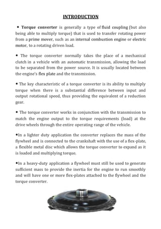
1) An introduction describing torque converters and their role in automatic transmissions.
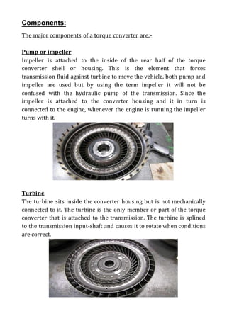
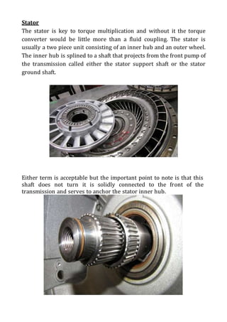
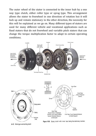
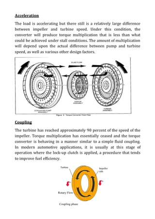
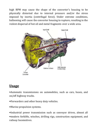
2) Descriptions of the major components of a torque converter including the impeller, turbine, and stator.
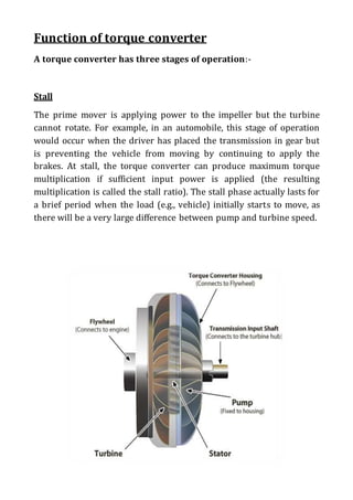
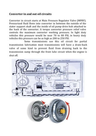
3) An explanation of how torque converters function in stall, acceleration, and coupling phases.