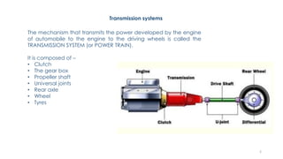
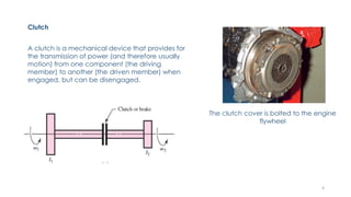
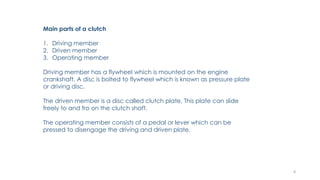
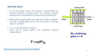
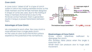
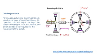
SlideShare a Scribd company logo
1
Transmission systems
The mechanism that transmits the power developed by the engine
of automobile to the engine to the driving wheels is called the
TRANSMISSION SYSTEM (or POWER TRAIN).
It is composed of –
• Clutch
• The gear box
• Propeller shaft
• Universal joints
• Rear axle
• Wheel
• Tyres
2
Requirements of Transmission System
• Provide means of connection and disconnection of engine with rest of power
train without shock and smoothly.
• Provide a varied leverage between the engine and the drive wheels.
• Provide means to transfer power in opposite direction.
• Enable speed reduction between engine and the drive wheels in the ratio of
5:1.
• Provide means to drive the driving wheels at different speeds when required.
• Bear the effect of torque reaction , driving thrust and braking effort effectively.
3
Clutch
A clutch is a mechanical device that provides for
the transmission of power (and therefore usually
motion) from one component (the driving
member) to another (the driven member) when
engaged, but can be disengaged.
The clutch cover is bolted to the engine
flywheel
4
Why Do we Need Clutch
In a car, you need a clutch because the engine spins all the time and the car
wheels don't. In order for a car to stop without killing the engine, the wheels
need to be disconnected from the engine somehow.
The clutch allows us to smoothly engage a spinning engine to a nonspinning
transmission by controlling the slippage between them. To understand how a
clutch works, it helps to know a little bit about friction.
5
Function of Clutch
1. When the clutch is engaged, the power flows from the engine to the wheels
through the transmission system and the vehicle moves.
2. When the clutch is disengaged, the power is not transmitted to the wheels and
the vehicles stops while the engine is still running.
3. The clutch is kept engaged when the vehicle is moving.
4. The clutch also permits the gradual taking up of the load. When properly
operated, it prevents jerky motion of the vehicle.
5. The clutch is disengaged :- i) when starting the engine. ii) when shifting the
gears. iii) when stopping the vehicle. iv) when idling the engine.
6
Principle of Operation
The clutch works on the principles of friction. When two friction
surfaces are brought in contact with each other and pressed they
are united due to the friction between them.
The friction between the surfaces depends upon:-
i) Nature of the surfaces.
ii) applied pressure.
iii) co-efficient of friction.
The two surfaces can be separated and brought into contact when
required. One surface is considered as driving member and other as
driven member. The driving member is kept rotating.
7
Main parts of a clutch
1. Driving member
2. Driven member
3. Operating member
Driving member has a flywheel which is mounted on the engine
crankshaft. A disc is bolted to flywheel which is known as pressure plate
or driving disc.
The driven member is a disc called clutch plate. This plate can slide
freely to and fro on the clutch shaft.
The operating member consists of a pedal or lever which can be
pressed to disengage the driving and driven plate.
8
Classification
9
Two halves carrying projections or halves
• One half is fixed and the other can move along the axis
• Jaws of moving half enter into socket of mating half •
Eg. Square jaw, spiral jaw
Advantages
• No slip and positive engagement
• No heat during engagement/disengagement Drawbacks • Engagement only
when stationary or rotate at very low speed • High speed engagement results in
shocks
Positive Contact Clutches
10
Friction Clutch: Single plate
Disengaged position engaged position
https://www.youtube.com/watch?v=devo3kdSPQY
11
• A single plate clutch has one clutch plate. This
clutch works on the principle of friction. It is the most
common type of clutch used in motor vehicles.
• The clutch primarily consists of two members, one
mounted on the driving shaft and the other on the
driven shaft.
• These two shafts are parallel and concentric with
each other; one shaft is fixed to its housing while the
other is splined so that it can move axially.
• The driving torque can increase by increasing the
effective radius of contact.
12
Pressure plate and housing
Clutch plate or friction plate
𝑇 = 𝜇𝑊𝑟 𝑚
13
Applications
Single plate clutches are used where large radial space is available. e.g. cars, buses, and trucks.
Advantages
• The working of engagement and disengagement is very smooth in a single plate clutch.
• Power losses are very less.
• As sufficient surface area is available for heat dissipation in such clutches, no cooling oil is
required. Therefore, single plate clutches are dry type.
• Single plate clutches have a quick operation and respond fast.
• It makes it easier to change gears than a cone type.
Disadvantages
• Single plate clutches have high wear and tear rate.
• It has less torque transmitting capacity.
• The springs have to be the more stiff hence greater force requires to disengage.
• It requires high maintenance.
• The space required to accommodate the clutch is more as compared to the multi-plate clutch.
14
Multi Plate Clutch
• In a multi plate clutch, the torque is transmitted by
friction between several pairs of co-axial annular
driving faces maintained in contact by an axial thrust.
• Both sides of each plate are lined with friction material,
so that a single-plate clutch has two pairs of driving
faces in contact.
• n = no. of pairs of driving faces.
• Then, for a plate clutch, the maximum torque
transmitted is
mWrnT 
No. of driving
pairs n = 6
https://www.youtube.com/watch?v=TcYsV063lk8
15
Applications
• Multi-plate clutches use where compact construction is required, e.g., scooters,
motorcycles, and racing cars.
• The multi-plate clasp use in heavy commercial vehicles to transmit high torque.
Advantages
• Decrease the weight of the clutch.
• It has a very compact size.
• Increase the amount of torque transmits.
• Decrease the moment of inertia of the clutch.
Disadvantages
• They heat up quickly.
• Multi-plate clutches are heavy.
• Multi-plate clutches are too expensive.
16
Cone clutch
A cone clutch “oldest of all” Is a type of clutch
system in which two mating members known as the
male member and the female member designed
in shape of cones are used, due to the mating of
these 2 members frictional force due to the
frictional contact between them is generated
results in torque or power transmission between
them.
Advantages of Cone Clutch:
•As compared to each other, the cone clutch is
more efficient than a single plate clutch.
•In the case of cone clutch the friction surface
experience the potential of the normal force.
Disadvantages of Cone Clutch:
•Cone clutch oftentimes inefficient to
disengage the clutch.
•This situation takes place when the angle is
more than 20°.
•Small wear can produce due to huge axial
movement.
17
Centrifugal Clutch
For engaging clutches, Centrifugal clutch
uses the concept of centrifugal force. It is
operated automatically according to the
speed of an engine. Thus, in a vehicle, any
clutch paddle is not required for the
movement of the clutch.
https://www.youtube.com/watch?v=HrmWNBwHBQ018
Advantages of Centrifugal Clutch:
These are the advantages of Centrifugal Clutch:
• It is automatic.
• Low cost and also low maintenance cost.
• Less wear and tear.
• Greater control over speed.
Disadvantages of Centrifugal Clutch:
Here are some disadvantages of Centrifugal Clutch:
Sometimes, engines suffer from slippage in lower RPM.
It cannot be used in a high-speed engine.
Peak speed depends on clutch size.
19
20
https://www.youtube.com/watch?v=5SuqyE_bXqo
Electromagnetic clutch
Electromagnetic clutches operate electrically but
transmit torque mechanically. This is why they used to
be referred to as electro-mechanical clutches.
How it works
When the clutch is actuated, current flows through
the electromagnet producing a magnetic field. The
rotor portion of the clutch becomes magnetized
and sets up a magnetic loop that attracts the
armature. The armature is pulled against the rotor
and a frictional force is generated at contact.
Within a relatively short time, the load is
accelerated to match the speed of the rotor,
thereby engaging the armature and the output hub
of the clutch. In most instances, the rotor is
constantly rotating with the input all the time.
21
Disengagement
When current is removed from the clutch, the armature is free to turn with the shaft. In
most designs, springs hold the armature away from the rotor surface when power is
released, creating a small air gap.
Cycling
Cycling is achieved by interrupting the current through the electromagnet. Slippage
normally occurs only during acceleration. When the clutch is fully engaged, there is no
relative slip, assuming the clutch is sized properly, and thus torque transfer is 100%
efficient.
Applications
Machinery, Vehicles, and Diesel locomotives
22
https://www.youtube.com/watch?v=z5G2zQ_3xTc
Torque Convertor
A torque converter is generally a type of fluid coupling
capable of producing torque.
• Replacement of clutch for automatic transmission
vehicle.
It has two important purposes as it transfers the engine
torque to the transmission:
• It serves as an automatic clutch so the vehicle can be
stopped with the engine running and the transmission in
gear.
• It multiplies torque while the vehicle is accelerating to
improve acceleration and pulling power.
Parts of a torque convertor
1. Impeller- Connected to the flywheel and towards the
gearbox.
2. Turbine-Facing the impeller and the main shaft of the
gear box is taken from the turbine through the impeller.
3. Stator-Between the impeller and turbine
23
24
Operational phases
A torque converter has three stages of operation:
Stall
The prime mover is applying power to the impeller but the turbine cannot rotate. For example, in an
automobile, this stage of operation would occur when the driver has placed the transmission in gear
but is preventing the vehicle from moving by continuing to apply the brakes. At stall, the torque
converter can produce maximum torque multiplication if sufficient input power is applied (the
resulting multiplication is called the stall ratio). The stall phase actually lasts for a brief period when the
load (e.g., vehicle) initially starts to move, as there will be a very large difference between pump and
turbine speed.
Acceleration The load is accelerating but there still is a relatively large difference between impeller
and turbine speed. Under this condition, the converter will produce torque multiplication that is less
than what could be achieved under stall conditions. The amount of multiplication will depend upon
the actual difference between pump and turbine speed, as well as various other design factors.
Coupling The turbine has reached approximately 90 percent of the speed of the impeller. Torque
multiplication has essentially ceased and the torque converter is behaving in a manner similar to a
simple fluid coupling. In modern automotive applications, it is usually at this stage of operation where
the lock-up clutch is applied, a procedure that tends to improve fuel efficiency.
25
The two major operating conditions of a converter are stall and coupling.
These conditions shift back and forth depending on throttle opening and
vehicle load.
FIGURE 9-12 The fluid flowing around the guide ring is called vortex flow
(a). The fluid flow around the converter is called rotary flow (b). (Courtesy
of Chrysler Corporation)
26
The fluid flow from the turbine is turned to the same direction as
the impeller by the stator vanes.
The vortex flow, torque multiplication, and efficiency of a torque converter
change as the turbine speed increases relative to the impeller.
27
The maximum amount of torque multiplication produced by a converter is highly dependent on
the size and geometry of the turbine and stator blades, and is generated only when the
converter is at or near the stall phase of operation. Typical stall torque multiplication ratios range
from 1.8:1 to 2.5:1 for most automotive applications.
Failure Problems
• Overheating-Continuous high levels of slippage resulting in damage to the seals that retain
fluid inside the converter.
• Stator clutch seizure- The inner and outer elements of the one way stator clutch become
permanently locked together, thus preventing the stator from rotating during the coupling
phase.
• Stator clutch breakage- A very abrupt application of power can cause shock loading of the
stator clutch, resulting in breakage.
• Blade deformation and fragmentation- If subjected to abrupt loading or excessive heating of
the converter, pump and/or turbine blades may be deformed.
• Balloning-Operating a torque converter at very high RPM may cause the shape of the
converter's housing to be physically distorted due to internal pressure.
28
Fluid coupling vs Torque convertor
A fluid coupling is a two element drive that is incapable of multiplying torque, while a
torque converter has at least one extra element—the stator—which alters the drive's
characteristics during periods of high slippage, producing an increase in output
torque.
Fluid coupling - acts as a automatic clutch without torque multiplication.
Torque convertor - is essentially an automatic clutch and torque multiplication device

More Related Content

What's hot

1. clutch
1. clutch1. clutch
1. clutch
Peeyush Chauhan
 
Clutch and Gear
Clutch and GearClutch and Gear
Clutch and Gear
nagesh surner
 
Clutch ppt
Clutch pptClutch ppt
Clutch ppt
ANIL SHARMA
 
Clutch of Motor Bike
Clutch of Motor BikeClutch of Motor Bike
Clutch of Motor Bike
Muhammad Umair Akram
 
Brakes ppt
Brakes pptBrakes ppt
Brakes ppt
Yashodhan Agarwal
 
Automobile module II
Automobile module IIAutomobile module II
Automobile module II
ANOOP P
 
Braking system
Braking systemBraking system
Braking system
Yashodhan Agarwal
 
Clutches for automobile
Clutches for automobile Clutches for automobile
Clutches for automobile sgrsoni45
 
Suspension System
Suspension SystemSuspension System
Suspension System
Aniket Gavali
 
Gearboxes in auto
Gearboxes in autoGearboxes in auto
Gearboxes in autoSam Cheng
 
Assist and Slipper Clutch | ART- Slipper Clutch Technology
 Assist and Slipper Clutch | ART- Slipper Clutch Technology Assist and Slipper Clutch | ART- Slipper Clutch Technology
Assist and Slipper Clutch | ART- Slipper Clutch Technology
Kiran Poojary
 
Agriculture Engineering-chptr 9 power transmission
Agriculture Engineering-chptr 9 power transmissionAgriculture Engineering-chptr 9 power transmission
Agriculture Engineering-chptr 9 power transmissionwatak manga pilu
 
Clutch mechanism unit 2
Clutch mechanism unit 2Clutch mechanism unit 2
Clutch mechanism unit 2
Arunendra singh Chauhan
 
Automotive transmission mechanism
Automotive transmission mechanism Automotive transmission mechanism
Automotive transmission mechanism
Darshan H Patel
 
Summer training report
Summer training reportSummer training report
Summer training report
Asha Kumari
 
Assignment on 'Clutch'
Assignment on 'Clutch'Assignment on 'Clutch'
Assignment on 'Clutch'
Salim Azad
 
Unit-3-Transmission system of Automobile
Unit-3-Transmission system of Automobile Unit-3-Transmission system of Automobile
Unit-3-Transmission system of Automobile
Dr.S.SURESH
 
differential gear mechanism BY ANUBHAV SINGH
differential gear mechanism BY ANUBHAV SINGHdifferential gear mechanism BY ANUBHAV SINGH
differential gear mechanism BY ANUBHAV SINGH
Anubhav659
 
Presentation1
Presentation1Presentation1
Presentation1
ankit maurya
 

What's hot (20)

1. clutch
1. clutch1. clutch
1. clutch
 
Clutch and Gear
Clutch and GearClutch and Gear
Clutch and Gear
 
Clutch ppt
Clutch pptClutch ppt
Clutch ppt
 
Clutch of Motor Bike
Clutch of Motor BikeClutch of Motor Bike
Clutch of Motor Bike
 
Brakes ppt
Brakes pptBrakes ppt
Brakes ppt
 
Automobile module II
Automobile module IIAutomobile module II
Automobile module II
 
Braking system
Braking systemBraking system
Braking system
 
Clutches for automobile
Clutches for automobile Clutches for automobile
Clutches for automobile
 
Suspension System
Suspension SystemSuspension System
Suspension System
 
Gearboxes in auto
Gearboxes in autoGearboxes in auto
Gearboxes in auto
 
Clutch
ClutchClutch
Clutch
 
Assist and Slipper Clutch | ART- Slipper Clutch Technology
 Assist and Slipper Clutch | ART- Slipper Clutch Technology Assist and Slipper Clutch | ART- Slipper Clutch Technology
Assist and Slipper Clutch | ART- Slipper Clutch Technology
 
Agriculture Engineering-chptr 9 power transmission
Agriculture Engineering-chptr 9 power transmissionAgriculture Engineering-chptr 9 power transmission
Agriculture Engineering-chptr 9 power transmission
 
Clutch mechanism unit 2
Clutch mechanism unit 2Clutch mechanism unit 2
Clutch mechanism unit 2
 
Automotive transmission mechanism
Automotive transmission mechanism Automotive transmission mechanism
Automotive transmission mechanism
 
Summer training report
Summer training reportSummer training report
Summer training report
 
Assignment on 'Clutch'
Assignment on 'Clutch'Assignment on 'Clutch'
Assignment on 'Clutch'
 
Unit-3-Transmission system of Automobile
Unit-3-Transmission system of Automobile Unit-3-Transmission system of Automobile
Unit-3-Transmission system of Automobile
 
differential gear mechanism BY ANUBHAV SINGH
differential gear mechanism BY ANUBHAV SINGHdifferential gear mechanism BY ANUBHAV SINGH
differential gear mechanism BY ANUBHAV SINGH
 
Presentation1
Presentation1Presentation1
Presentation1
 

Similar to Transmission system_clutch

Types of Transmission
Types of TransmissionTypes of Transmission
Types of Transmission
NILESH MISHRA
 
UNIT-III-TRANSMISSION SYSTEMS REAR AXLES
UNIT-III-TRANSMISSION SYSTEMS REAR AXLESUNIT-III-TRANSMISSION SYSTEMS REAR AXLES
UNIT-III-TRANSMISSION SYSTEMS REAR AXLES
DineshKumar4165
 
UNIT-III-TRANSMISSION SYSTEMS.pptx
UNIT-III-TRANSMISSION SYSTEMS.pptxUNIT-III-TRANSMISSION SYSTEMS.pptx
UNIT-III-TRANSMISSION SYSTEMS.pptx
ShanmathyAR2
 
UNIT-III-TRANSMISSION SYSTEMS.pptx
UNIT-III-TRANSMISSION SYSTEMS.pptxUNIT-III-TRANSMISSION SYSTEMS.pptx
UNIT-III-TRANSMISSION SYSTEMS.pptx
prakash0712
 
Transmission system of Automobiles
Transmission system of AutomobilesTransmission system of Automobiles
Transmission system of Automobiles
PraveenManickam2
 
CLUTCHES.pptx
CLUTCHES.pptxCLUTCHES.pptx
CLUTCHES.pptx
PraneethPV1
 
Automobile transmission.pptx
Automobile transmission.pptxAutomobile transmission.pptx
Automobile transmission.pptx
ProfDrDileepK
 
Multi-plate clutch
Multi-plate clutch Multi-plate clutch
Multi-plate clutch
ThaRun InTel
 
Disc Clutch
Disc ClutchDisc Clutch
Disc Clutch
Neel Patel
 
Unit iii
Unit iiiUnit iii
Unit iii
SelvamV17
 
Clutch ppt
Clutch pptClutch ppt
Clutch ppt
jayantjmd
 
Gear Box and Torque Converter- CSVTU
Gear Box and Torque Converter- CSVTUGear Box and Torque Converter- CSVTU
Gear Box and Torque Converter- CSVTU
ManishRKSahu
 
Gear boxes
Gear boxesGear boxes
automotivetransmissionmechanism-140904070720-phpapp01.ppt
automotivetransmissionmechanism-140904070720-phpapp01.pptautomotivetransmissionmechanism-140904070720-phpapp01.ppt
automotivetransmissionmechanism-140904070720-phpapp01.ppt
Rahul_urunkar
 
transmission.pdf
transmission.pdftransmission.pdf
transmission.pdf
halilyldrm13
 
Automotive transmission system
Automotive transmission systemAutomotive transmission system
Automotive transmission system
Dr. M. Usman Ghani
 
Koushik 20151026-093718
Koushik 20151026-093718Koushik 20151026-093718
Koushik 20151026-093718
koushik17
 
Ppt automobile
Ppt automobile  Ppt automobile
Ppt automobile
suhas kale
 
Clutch
ClutchClutch
Clutch
yash patel
 
automotive transmission system clutch and system
automotive transmission system clutch and systemautomotive transmission system clutch and system
automotive transmission system clutch and system
THESRIF
 

Similar to Transmission system_clutch (20)

Types of Transmission
Types of TransmissionTypes of Transmission
Types of Transmission
 
UNIT-III-TRANSMISSION SYSTEMS REAR AXLES
UNIT-III-TRANSMISSION SYSTEMS REAR AXLESUNIT-III-TRANSMISSION SYSTEMS REAR AXLES
UNIT-III-TRANSMISSION SYSTEMS REAR AXLES
 
UNIT-III-TRANSMISSION SYSTEMS.pptx
UNIT-III-TRANSMISSION SYSTEMS.pptxUNIT-III-TRANSMISSION SYSTEMS.pptx
UNIT-III-TRANSMISSION SYSTEMS.pptx
 
UNIT-III-TRANSMISSION SYSTEMS.pptx
UNIT-III-TRANSMISSION SYSTEMS.pptxUNIT-III-TRANSMISSION SYSTEMS.pptx
UNIT-III-TRANSMISSION SYSTEMS.pptx
 
Transmission system of Automobiles
Transmission system of AutomobilesTransmission system of Automobiles
Transmission system of Automobiles
 
CLUTCHES.pptx
CLUTCHES.pptxCLUTCHES.pptx
CLUTCHES.pptx
 
Automobile transmission.pptx
Automobile transmission.pptxAutomobile transmission.pptx
Automobile transmission.pptx
 
Multi-plate clutch
Multi-plate clutch Multi-plate clutch
Multi-plate clutch
 
Disc Clutch
Disc ClutchDisc Clutch
Disc Clutch
 
Unit iii
Unit iiiUnit iii
Unit iii
 
Clutch ppt
Clutch pptClutch ppt
Clutch ppt
 
Gear Box and Torque Converter- CSVTU
Gear Box and Torque Converter- CSVTUGear Box and Torque Converter- CSVTU
Gear Box and Torque Converter- CSVTU
 
Gear boxes
Gear boxesGear boxes
Gear boxes
 
automotivetransmissionmechanism-140904070720-phpapp01.ppt
automotivetransmissionmechanism-140904070720-phpapp01.pptautomotivetransmissionmechanism-140904070720-phpapp01.ppt
automotivetransmissionmechanism-140904070720-phpapp01.ppt
 
transmission.pdf
transmission.pdftransmission.pdf
transmission.pdf
 
Automotive transmission system
Automotive transmission systemAutomotive transmission system
Automotive transmission system
 
Koushik 20151026-093718
Koushik 20151026-093718Koushik 20151026-093718
Koushik 20151026-093718
 
Ppt automobile
Ppt automobile  Ppt automobile
Ppt automobile
 
Clutch
ClutchClutch
Clutch
 
automotive transmission system clutch and system
automotive transmission system clutch and systemautomotive transmission system clutch and system
automotive transmission system clutch and system
 

More from Devendra Yadav

Axle
AxleAxle
Recent trends in chassis system
Recent trends in chassis systemRecent trends in chassis system
Recent trends in chassis system
Devendra Yadav
 
Presentation: Wheels tyres and bearings
Presentation: Wheels tyres and bearingsPresentation: Wheels tyres and bearings
Presentation: Wheels tyres and bearings
Devendra Yadav
 
Braking system in automobile
Braking system in automobileBraking system in automobile
Braking system in automobile
Devendra Yadav
 
Suspension system in automobile
Suspension system in automobileSuspension system in automobile
Suspension system in automobile
Devendra Yadav
 
Final Drive_Differential
Final Drive_Differential Final Drive_Differential
Final Drive_Differential
Devendra Yadav
 
Propeller shaft
Propeller shaftPropeller shaft
Propeller shaft
Devendra Yadav
 
Gear box classisfication
Gear box classisficationGear box classisfication
Gear box classisfication
Devendra Yadav
 
Gear and gear train
Gear  and gear trainGear  and gear train
Gear and gear train
Devendra Yadav
 
Materials in automotive design
Materials in automotive designMaterials in automotive design
Materials in automotive design
Devendra Yadav
 
Loads acting on frame
Loads acting on frameLoads acting on frame
Loads acting on frame
Devendra Yadav
 
chassis frame
chassis frame chassis frame
chassis frame
Devendra Yadav
 
Automobile and chassis
Automobile and chassisAutomobile and chassis
Automobile and chassis
Devendra Yadav
 
Automotive Chassis and Suspension (KAU 052) notes_introduction 2
Automotive Chassis and Suspension (KAU 052) notes_introduction 2Automotive Chassis and Suspension (KAU 052) notes_introduction 2
Automotive Chassis and Suspension (KAU 052) notes_introduction 2
Devendra Yadav
 

More from Devendra Yadav (14)

Axle
AxleAxle
Axle
 
Recent trends in chassis system
Recent trends in chassis systemRecent trends in chassis system
Recent trends in chassis system
 
Presentation: Wheels tyres and bearings
Presentation: Wheels tyres and bearingsPresentation: Wheels tyres and bearings
Presentation: Wheels tyres and bearings
 
Braking system in automobile
Braking system in automobileBraking system in automobile
Braking system in automobile
 
Suspension system in automobile
Suspension system in automobileSuspension system in automobile
Suspension system in automobile
 
Final Drive_Differential
Final Drive_Differential Final Drive_Differential
Final Drive_Differential
 
Propeller shaft
Propeller shaftPropeller shaft
Propeller shaft
 
Gear box classisfication
Gear box classisficationGear box classisfication
Gear box classisfication
 
Gear and gear train
Gear  and gear trainGear  and gear train
Gear and gear train
 
Materials in automotive design
Materials in automotive designMaterials in automotive design
Materials in automotive design
 
Loads acting on frame
Loads acting on frameLoads acting on frame
Loads acting on frame
 
chassis frame
chassis frame chassis frame
chassis frame
 
Automobile and chassis
Automobile and chassisAutomobile and chassis
Automobile and chassis
 
Automotive Chassis and Suspension (KAU 052) notes_introduction 2
Automotive Chassis and Suspension (KAU 052) notes_introduction 2Automotive Chassis and Suspension (KAU 052) notes_introduction 2
Automotive Chassis and Suspension (KAU 052) notes_introduction 2
 

Recently uploaded

Tutorial for 16S rRNA Gene Analysis with QIIME2.pdf
Tutorial for 16S rRNA Gene Analysis with QIIME2.pdfTutorial for 16S rRNA Gene Analysis with QIIME2.pdf
Tutorial for 16S rRNA Gene Analysis with QIIME2.pdf
aqil azizi
 
KuberTENes Birthday Bash Guadalajara - K8sGPT first impressions
KuberTENes Birthday Bash Guadalajara - K8sGPT first impressionsKuberTENes Birthday Bash Guadalajara - K8sGPT first impressions
KuberTENes Birthday Bash Guadalajara - K8sGPT first impressions
Victor Morales
 
Planning Of Procurement o different goods and services
Planning Of Procurement o different goods and servicesPlanning Of Procurement o different goods and services
Planning Of Procurement o different goods and services
JoytuBarua2
 
一比一原版(Otago毕业证)奥塔哥大学毕业证成绩单如何办理
一比一原版(Otago毕业证)奥塔哥大学毕业证成绩单如何办理一比一原版(Otago毕业证)奥塔哥大学毕业证成绩单如何办理
一比一原版(Otago毕业证)奥塔哥大学毕业证成绩单如何办理
dxobcob
 
ACRP 4-09 Risk Assessment Method to Support Modification of Airfield Separat...
ACRP 4-09 Risk Assessment Method to Support Modification of Airfield Separat...ACRP 4-09 Risk Assessment Method to Support Modification of Airfield Separat...
ACRP 4-09 Risk Assessment Method to Support Modification of Airfield Separat...
Mukeshwaran Balu
 
一比一原版(UofT毕业证)多伦多大学毕业证成绩单如何办理
一比一原版(UofT毕业证)多伦多大学毕业证成绩单如何办理一比一原版(UofT毕业证)多伦多大学毕业证成绩单如何办理
一比一原版(UofT毕业证)多伦多大学毕业证成绩单如何办理
ydteq
 
sieving analysis and results interpretation
sieving analysis and results interpretationsieving analysis and results interpretation
sieving analysis and results interpretation
ssuser36d3051
 
Swimming pool mechanical components design.pptx
Swimming pool  mechanical components design.pptxSwimming pool  mechanical components design.pptx
Swimming pool mechanical components design.pptx
yokeleetan1
 
spirit beverages ppt without graphics.pptx
spirit beverages ppt without graphics.pptxspirit beverages ppt without graphics.pptx
spirit beverages ppt without graphics.pptx
Madan Karki
 
DfMAy 2024 - key insights and contributions
DfMAy 2024 - key insights and contributionsDfMAy 2024 - key insights and contributions
DfMAy 2024 - key insights and contributions
gestioneergodomus
 
Recycled Concrete Aggregate in Construction Part III
Recycled Concrete Aggregate in Construction Part IIIRecycled Concrete Aggregate in Construction Part III
Recycled Concrete Aggregate in Construction Part III
Aditya Rajan Patra
 
原版制作(unimelb毕业证书)墨尔本大学毕业证Offer一模一样
原版制作(unimelb毕业证书)墨尔本大学毕业证Offer一模一样原版制作(unimelb毕业证书)墨尔本大学毕业证Offer一模一样
原版制作(unimelb毕业证书)墨尔本大学毕业证Offer一模一样
obonagu
 
Technical Drawings introduction to drawing of prisms
Technical Drawings introduction to drawing of prismsTechnical Drawings introduction to drawing of prisms
Technical Drawings introduction to drawing of prisms
heavyhaig
 
digital fundamental by Thomas L.floydl.pdf
digital fundamental by Thomas L.floydl.pdfdigital fundamental by Thomas L.floydl.pdf
digital fundamental by Thomas L.floydl.pdf
drwaing
 
Low power architecture of logic gates using adiabatic techniques
Low power architecture of logic gates using adiabatic techniquesLow power architecture of logic gates using adiabatic techniques
Low power architecture of logic gates using adiabatic techniques
nooriasukmaningtyas
 
Modelagem de um CSTR com reação endotermica.pdf
Modelagem de um CSTR com reação endotermica.pdfModelagem de um CSTR com reação endotermica.pdf
Modelagem de um CSTR com reação endotermica.pdf
camseq
 
Heap Sort (SS).ppt FOR ENGINEERING GRADUATES, BCA, MCA, MTECH, BSC STUDENTS
Heap Sort (SS).ppt FOR ENGINEERING GRADUATES, BCA, MCA, MTECH, BSC STUDENTSHeap Sort (SS).ppt FOR ENGINEERING GRADUATES, BCA, MCA, MTECH, BSC STUDENTS
Heap Sort (SS).ppt FOR ENGINEERING GRADUATES, BCA, MCA, MTECH, BSC STUDENTS
Soumen Santra
 
哪里办理(csu毕业证书)查尔斯特大学毕业证硕士学历原版一模一样
哪里办理(csu毕业证书)查尔斯特大学毕业证硕士学历原版一模一样哪里办理(csu毕业证书)查尔斯特大学毕业证硕士学历原版一模一样
哪里办理(csu毕业证书)查尔斯特大学毕业证硕士学历原版一模一样
insn4465
 
Harnessing WebAssembly for Real-time Stateless Streaming Pipelines
Harnessing WebAssembly for Real-time Stateless Streaming PipelinesHarnessing WebAssembly for Real-time Stateless Streaming Pipelines
Harnessing WebAssembly for Real-time Stateless Streaming Pipelines
Christina Lin
 
一比一原版(IIT毕业证)伊利诺伊理工大学毕业证成绩单专业办理
一比一原版(IIT毕业证)伊利诺伊理工大学毕业证成绩单专业办理一比一原版(IIT毕业证)伊利诺伊理工大学毕业证成绩单专业办理
一比一原版(IIT毕业证)伊利诺伊理工大学毕业证成绩单专业办理
zwunae
 

Recently uploaded (20)

Tutorial for 16S rRNA Gene Analysis with QIIME2.pdf
Tutorial for 16S rRNA Gene Analysis with QIIME2.pdfTutorial for 16S rRNA Gene Analysis with QIIME2.pdf
Tutorial for 16S rRNA Gene Analysis with QIIME2.pdf
 
KuberTENes Birthday Bash Guadalajara - K8sGPT first impressions
KuberTENes Birthday Bash Guadalajara - K8sGPT first impressionsKuberTENes Birthday Bash Guadalajara - K8sGPT first impressions
KuberTENes Birthday Bash Guadalajara - K8sGPT first impressions
 
Planning Of Procurement o different goods and services
Planning Of Procurement o different goods and servicesPlanning Of Procurement o different goods and services
Planning Of Procurement o different goods and services
 
一比一原版(Otago毕业证)奥塔哥大学毕业证成绩单如何办理
一比一原版(Otago毕业证)奥塔哥大学毕业证成绩单如何办理一比一原版(Otago毕业证)奥塔哥大学毕业证成绩单如何办理
一比一原版(Otago毕业证)奥塔哥大学毕业证成绩单如何办理
 
ACRP 4-09 Risk Assessment Method to Support Modification of Airfield Separat...
ACRP 4-09 Risk Assessment Method to Support Modification of Airfield Separat...ACRP 4-09 Risk Assessment Method to Support Modification of Airfield Separat...
ACRP 4-09 Risk Assessment Method to Support Modification of Airfield Separat...
 
一比一原版(UofT毕业证)多伦多大学毕业证成绩单如何办理
一比一原版(UofT毕业证)多伦多大学毕业证成绩单如何办理一比一原版(UofT毕业证)多伦多大学毕业证成绩单如何办理
一比一原版(UofT毕业证)多伦多大学毕业证成绩单如何办理
 
sieving analysis and results interpretation
sieving analysis and results interpretationsieving analysis and results interpretation
sieving analysis and results interpretation
 
Swimming pool mechanical components design.pptx
Swimming pool  mechanical components design.pptxSwimming pool  mechanical components design.pptx
Swimming pool mechanical components design.pptx
 
spirit beverages ppt without graphics.pptx
spirit beverages ppt without graphics.pptxspirit beverages ppt without graphics.pptx
spirit beverages ppt without graphics.pptx
 
DfMAy 2024 - key insights and contributions
DfMAy 2024 - key insights and contributionsDfMAy 2024 - key insights and contributions
DfMAy 2024 - key insights and contributions
 
Recycled Concrete Aggregate in Construction Part III
Recycled Concrete Aggregate in Construction Part IIIRecycled Concrete Aggregate in Construction Part III
Recycled Concrete Aggregate in Construction Part III
 
原版制作(unimelb毕业证书)墨尔本大学毕业证Offer一模一样
原版制作(unimelb毕业证书)墨尔本大学毕业证Offer一模一样原版制作(unimelb毕业证书)墨尔本大学毕业证Offer一模一样
原版制作(unimelb毕业证书)墨尔本大学毕业证Offer一模一样
 
Technical Drawings introduction to drawing of prisms
Technical Drawings introduction to drawing of prismsTechnical Drawings introduction to drawing of prisms
Technical Drawings introduction to drawing of prisms
 
digital fundamental by Thomas L.floydl.pdf
digital fundamental by Thomas L.floydl.pdfdigital fundamental by Thomas L.floydl.pdf
digital fundamental by Thomas L.floydl.pdf
 
Low power architecture of logic gates using adiabatic techniques
Low power architecture of logic gates using adiabatic techniquesLow power architecture of logic gates using adiabatic techniques
Low power architecture of logic gates using adiabatic techniques
 
Modelagem de um CSTR com reação endotermica.pdf
Modelagem de um CSTR com reação endotermica.pdfModelagem de um CSTR com reação endotermica.pdf
Modelagem de um CSTR com reação endotermica.pdf
 
Heap Sort (SS).ppt FOR ENGINEERING GRADUATES, BCA, MCA, MTECH, BSC STUDENTS
Heap Sort (SS).ppt FOR ENGINEERING GRADUATES, BCA, MCA, MTECH, BSC STUDENTSHeap Sort (SS).ppt FOR ENGINEERING GRADUATES, BCA, MCA, MTECH, BSC STUDENTS
Heap Sort (SS).ppt FOR ENGINEERING GRADUATES, BCA, MCA, MTECH, BSC STUDENTS
 
哪里办理(csu毕业证书)查尔斯特大学毕业证硕士学历原版一模一样
哪里办理(csu毕业证书)查尔斯特大学毕业证硕士学历原版一模一样哪里办理(csu毕业证书)查尔斯特大学毕业证硕士学历原版一模一样
哪里办理(csu毕业证书)查尔斯特大学毕业证硕士学历原版一模一样
 
Harnessing WebAssembly for Real-time Stateless Streaming Pipelines
Harnessing WebAssembly for Real-time Stateless Streaming PipelinesHarnessing WebAssembly for Real-time Stateless Streaming Pipelines
Harnessing WebAssembly for Real-time Stateless Streaming Pipelines
 
一比一原版(IIT毕业证)伊利诺伊理工大学毕业证成绩单专业办理
一比一原版(IIT毕业证)伊利诺伊理工大学毕业证成绩单专业办理一比一原版(IIT毕业证)伊利诺伊理工大学毕业证成绩单专业办理
一比一原版(IIT毕业证)伊利诺伊理工大学毕业证成绩单专业办理
 

Transmission system_clutch

  • 1. 1
  • 2. Transmission systems The mechanism that transmits the power developed by the engine of automobile to the engine to the driving wheels is called the TRANSMISSION SYSTEM (or POWER TRAIN). It is composed of – • Clutch • The gear box • Propeller shaft • Universal joints • Rear axle • Wheel • Tyres 2
  • 3. Requirements of Transmission System • Provide means of connection and disconnection of engine with rest of power train without shock and smoothly. • Provide a varied leverage between the engine and the drive wheels. • Provide means to transfer power in opposite direction. • Enable speed reduction between engine and the drive wheels in the ratio of 5:1. • Provide means to drive the driving wheels at different speeds when required. • Bear the effect of torque reaction , driving thrust and braking effort effectively. 3
  • 4. Clutch A clutch is a mechanical device that provides for the transmission of power (and therefore usually motion) from one component (the driving member) to another (the driven member) when engaged, but can be disengaged. The clutch cover is bolted to the engine flywheel 4
  • 5. Why Do we Need Clutch In a car, you need a clutch because the engine spins all the time and the car wheels don't. In order for a car to stop without killing the engine, the wheels need to be disconnected from the engine somehow. The clutch allows us to smoothly engage a spinning engine to a nonspinning transmission by controlling the slippage between them. To understand how a clutch works, it helps to know a little bit about friction. 5
  • 6. Function of Clutch 1. When the clutch is engaged, the power flows from the engine to the wheels through the transmission system and the vehicle moves. 2. When the clutch is disengaged, the power is not transmitted to the wheels and the vehicles stops while the engine is still running. 3. The clutch is kept engaged when the vehicle is moving. 4. The clutch also permits the gradual taking up of the load. When properly operated, it prevents jerky motion of the vehicle. 5. The clutch is disengaged :- i) when starting the engine. ii) when shifting the gears. iii) when stopping the vehicle. iv) when idling the engine. 6
  • 7. Principle of Operation The clutch works on the principles of friction. When two friction surfaces are brought in contact with each other and pressed they are united due to the friction between them. The friction between the surfaces depends upon:- i) Nature of the surfaces. ii) applied pressure. iii) co-efficient of friction. The two surfaces can be separated and brought into contact when required. One surface is considered as driving member and other as driven member. The driving member is kept rotating. 7
  • 8. Main parts of a clutch 1. Driving member 2. Driven member 3. Operating member Driving member has a flywheel which is mounted on the engine crankshaft. A disc is bolted to flywheel which is known as pressure plate or driving disc. The driven member is a disc called clutch plate. This plate can slide freely to and fro on the clutch shaft. The operating member consists of a pedal or lever which can be pressed to disengage the driving and driven plate. 8
  • 10. Two halves carrying projections or halves • One half is fixed and the other can move along the axis • Jaws of moving half enter into socket of mating half • Eg. Square jaw, spiral jaw Advantages • No slip and positive engagement • No heat during engagement/disengagement Drawbacks • Engagement only when stationary or rotate at very low speed • High speed engagement results in shocks Positive Contact Clutches 10
  • 11. Friction Clutch: Single plate Disengaged position engaged position https://www.youtube.com/watch?v=devo3kdSPQY 11
  • 12. • A single plate clutch has one clutch plate. This clutch works on the principle of friction. It is the most common type of clutch used in motor vehicles. • The clutch primarily consists of two members, one mounted on the driving shaft and the other on the driven shaft. • These two shafts are parallel and concentric with each other; one shaft is fixed to its housing while the other is splined so that it can move axially. • The driving torque can increase by increasing the effective radius of contact. 12
  • 13. Pressure plate and housing Clutch plate or friction plate 𝑇 = 𝜇𝑊𝑟 𝑚 13
  • 14. Applications Single plate clutches are used where large radial space is available. e.g. cars, buses, and trucks. Advantages • The working of engagement and disengagement is very smooth in a single plate clutch. • Power losses are very less. • As sufficient surface area is available for heat dissipation in such clutches, no cooling oil is required. Therefore, single plate clutches are dry type. • Single plate clutches have a quick operation and respond fast. • It makes it easier to change gears than a cone type. Disadvantages • Single plate clutches have high wear and tear rate. • It has less torque transmitting capacity. • The springs have to be the more stiff hence greater force requires to disengage. • It requires high maintenance. • The space required to accommodate the clutch is more as compared to the multi-plate clutch. 14
  • 15. Multi Plate Clutch • In a multi plate clutch, the torque is transmitted by friction between several pairs of co-axial annular driving faces maintained in contact by an axial thrust. • Both sides of each plate are lined with friction material, so that a single-plate clutch has two pairs of driving faces in contact. • n = no. of pairs of driving faces. • Then, for a plate clutch, the maximum torque transmitted is mWrnT  No. of driving pairs n = 6 https://www.youtube.com/watch?v=TcYsV063lk8 15
  • 16. Applications • Multi-plate clutches use where compact construction is required, e.g., scooters, motorcycles, and racing cars. • The multi-plate clasp use in heavy commercial vehicles to transmit high torque. Advantages • Decrease the weight of the clutch. • It has a very compact size. • Increase the amount of torque transmits. • Decrease the moment of inertia of the clutch. Disadvantages • They heat up quickly. • Multi-plate clutches are heavy. • Multi-plate clutches are too expensive. 16
  • 17. Cone clutch A cone clutch “oldest of all” Is a type of clutch system in which two mating members known as the male member and the female member designed in shape of cones are used, due to the mating of these 2 members frictional force due to the frictional contact between them is generated results in torque or power transmission between them. Advantages of Cone Clutch: •As compared to each other, the cone clutch is more efficient than a single plate clutch. •In the case of cone clutch the friction surface experience the potential of the normal force. Disadvantages of Cone Clutch: •Cone clutch oftentimes inefficient to disengage the clutch. •This situation takes place when the angle is more than 20°. •Small wear can produce due to huge axial movement. 17
  • 18. Centrifugal Clutch For engaging clutches, Centrifugal clutch uses the concept of centrifugal force. It is operated automatically according to the speed of an engine. Thus, in a vehicle, any clutch paddle is not required for the movement of the clutch. https://www.youtube.com/watch?v=HrmWNBwHBQ018
  • 19. Advantages of Centrifugal Clutch: These are the advantages of Centrifugal Clutch: • It is automatic. • Low cost and also low maintenance cost. • Less wear and tear. • Greater control over speed. Disadvantages of Centrifugal Clutch: Here are some disadvantages of Centrifugal Clutch: Sometimes, engines suffer from slippage in lower RPM. It cannot be used in a high-speed engine. Peak speed depends on clutch size. 19
  • 20. 20 https://www.youtube.com/watch?v=5SuqyE_bXqo Electromagnetic clutch Electromagnetic clutches operate electrically but transmit torque mechanically. This is why they used to be referred to as electro-mechanical clutches. How it works When the clutch is actuated, current flows through the electromagnet producing a magnetic field. The rotor portion of the clutch becomes magnetized and sets up a magnetic loop that attracts the armature. The armature is pulled against the rotor and a frictional force is generated at contact. Within a relatively short time, the load is accelerated to match the speed of the rotor, thereby engaging the armature and the output hub of the clutch. In most instances, the rotor is constantly rotating with the input all the time.
  • 21. 21 Disengagement When current is removed from the clutch, the armature is free to turn with the shaft. In most designs, springs hold the armature away from the rotor surface when power is released, creating a small air gap. Cycling Cycling is achieved by interrupting the current through the electromagnet. Slippage normally occurs only during acceleration. When the clutch is fully engaged, there is no relative slip, assuming the clutch is sized properly, and thus torque transfer is 100% efficient. Applications Machinery, Vehicles, and Diesel locomotives
  • 22. 22 https://www.youtube.com/watch?v=z5G2zQ_3xTc Torque Convertor A torque converter is generally a type of fluid coupling capable of producing torque. • Replacement of clutch for automatic transmission vehicle. It has two important purposes as it transfers the engine torque to the transmission: • It serves as an automatic clutch so the vehicle can be stopped with the engine running and the transmission in gear. • It multiplies torque while the vehicle is accelerating to improve acceleration and pulling power. Parts of a torque convertor 1. Impeller- Connected to the flywheel and towards the gearbox. 2. Turbine-Facing the impeller and the main shaft of the gear box is taken from the turbine through the impeller. 3. Stator-Between the impeller and turbine
  • 23. 23
  • 24. 24 Operational phases A torque converter has three stages of operation: Stall The prime mover is applying power to the impeller but the turbine cannot rotate. For example, in an automobile, this stage of operation would occur when the driver has placed the transmission in gear but is preventing the vehicle from moving by continuing to apply the brakes. At stall, the torque converter can produce maximum torque multiplication if sufficient input power is applied (the resulting multiplication is called the stall ratio). The stall phase actually lasts for a brief period when the load (e.g., vehicle) initially starts to move, as there will be a very large difference between pump and turbine speed. Acceleration The load is accelerating but there still is a relatively large difference between impeller and turbine speed. Under this condition, the converter will produce torque multiplication that is less than what could be achieved under stall conditions. The amount of multiplication will depend upon the actual difference between pump and turbine speed, as well as various other design factors. Coupling The turbine has reached approximately 90 percent of the speed of the impeller. Torque multiplication has essentially ceased and the torque converter is behaving in a manner similar to a simple fluid coupling. In modern automotive applications, it is usually at this stage of operation where the lock-up clutch is applied, a procedure that tends to improve fuel efficiency.
  • 25. 25 The two major operating conditions of a converter are stall and coupling. These conditions shift back and forth depending on throttle opening and vehicle load. FIGURE 9-12 The fluid flowing around the guide ring is called vortex flow (a). The fluid flow around the converter is called rotary flow (b). (Courtesy of Chrysler Corporation)
  • 26. 26 The fluid flow from the turbine is turned to the same direction as the impeller by the stator vanes. The vortex flow, torque multiplication, and efficiency of a torque converter change as the turbine speed increases relative to the impeller.
  • 27. 27 The maximum amount of torque multiplication produced by a converter is highly dependent on the size and geometry of the turbine and stator blades, and is generated only when the converter is at or near the stall phase of operation. Typical stall torque multiplication ratios range from 1.8:1 to 2.5:1 for most automotive applications. Failure Problems • Overheating-Continuous high levels of slippage resulting in damage to the seals that retain fluid inside the converter. • Stator clutch seizure- The inner and outer elements of the one way stator clutch become permanently locked together, thus preventing the stator from rotating during the coupling phase. • Stator clutch breakage- A very abrupt application of power can cause shock loading of the stator clutch, resulting in breakage. • Blade deformation and fragmentation- If subjected to abrupt loading or excessive heating of the converter, pump and/or turbine blades may be deformed. • Balloning-Operating a torque converter at very high RPM may cause the shape of the converter's housing to be physically distorted due to internal pressure.
  • 28. 28 Fluid coupling vs Torque convertor A fluid coupling is a two element drive that is incapable of multiplying torque, while a torque converter has at least one extra element—the stator—which alters the drive's characteristics during periods of high slippage, producing an increase in output torque. Fluid coupling - acts as a automatic clutch without torque multiplication. Torque convertor - is essentially an automatic clutch and torque multiplication device