Downloaded 975 times
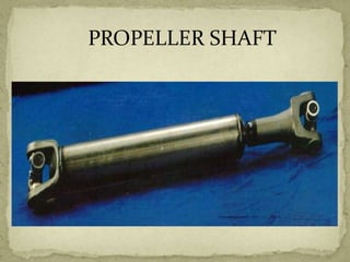
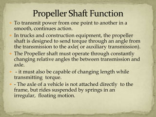
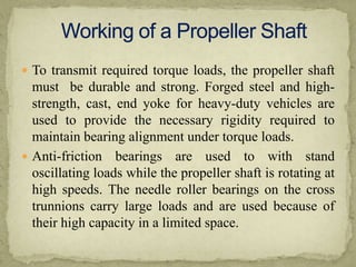
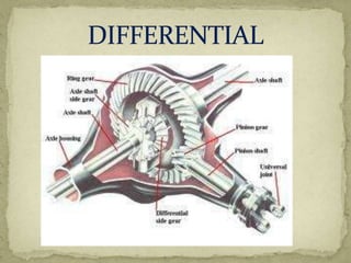
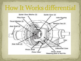
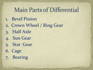
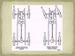


This document discusses the propeller shaft and differential in vehicles. It provides details on: 1) The purpose of the propeller shaft is to transmit power from the transmission to the axle while allowing for changes in length and angle. Special materials are used to withstand torque loads. 2) The differential receives engine power from the propeller shaft and transfers it to the rear wheels, allowing them to rotate at different speeds during turns. It uses bevel and planetary gears to distribute torque. 3) The differential gear mechanism allows the outside wheel to rotate faster during turns by allowing the side gears to rotate at different speeds, proportional to the load on each side. This permits the vehicle to turn smoothly.