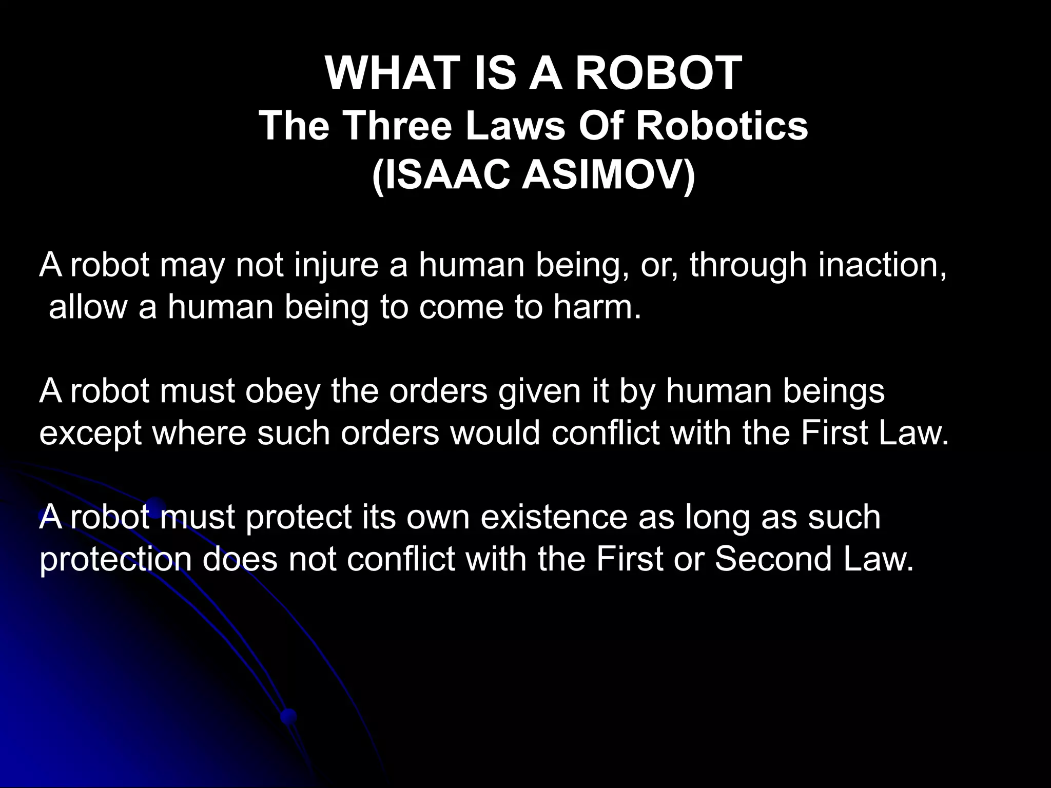
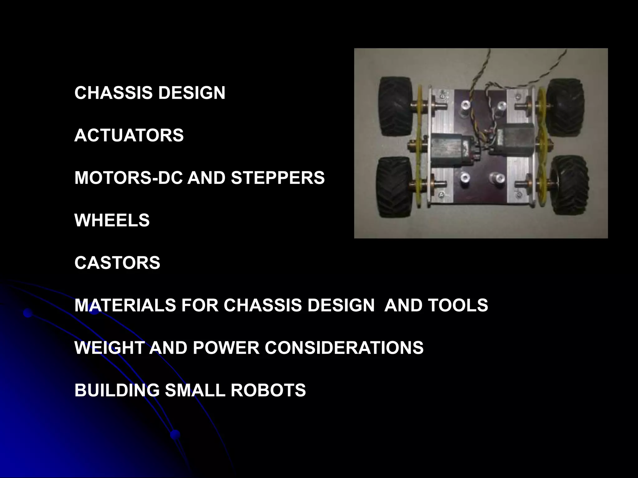
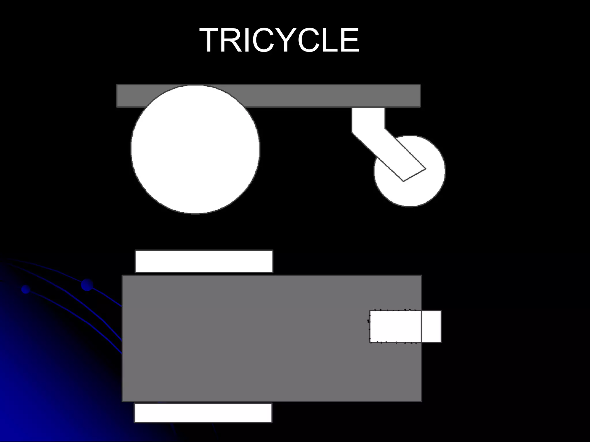
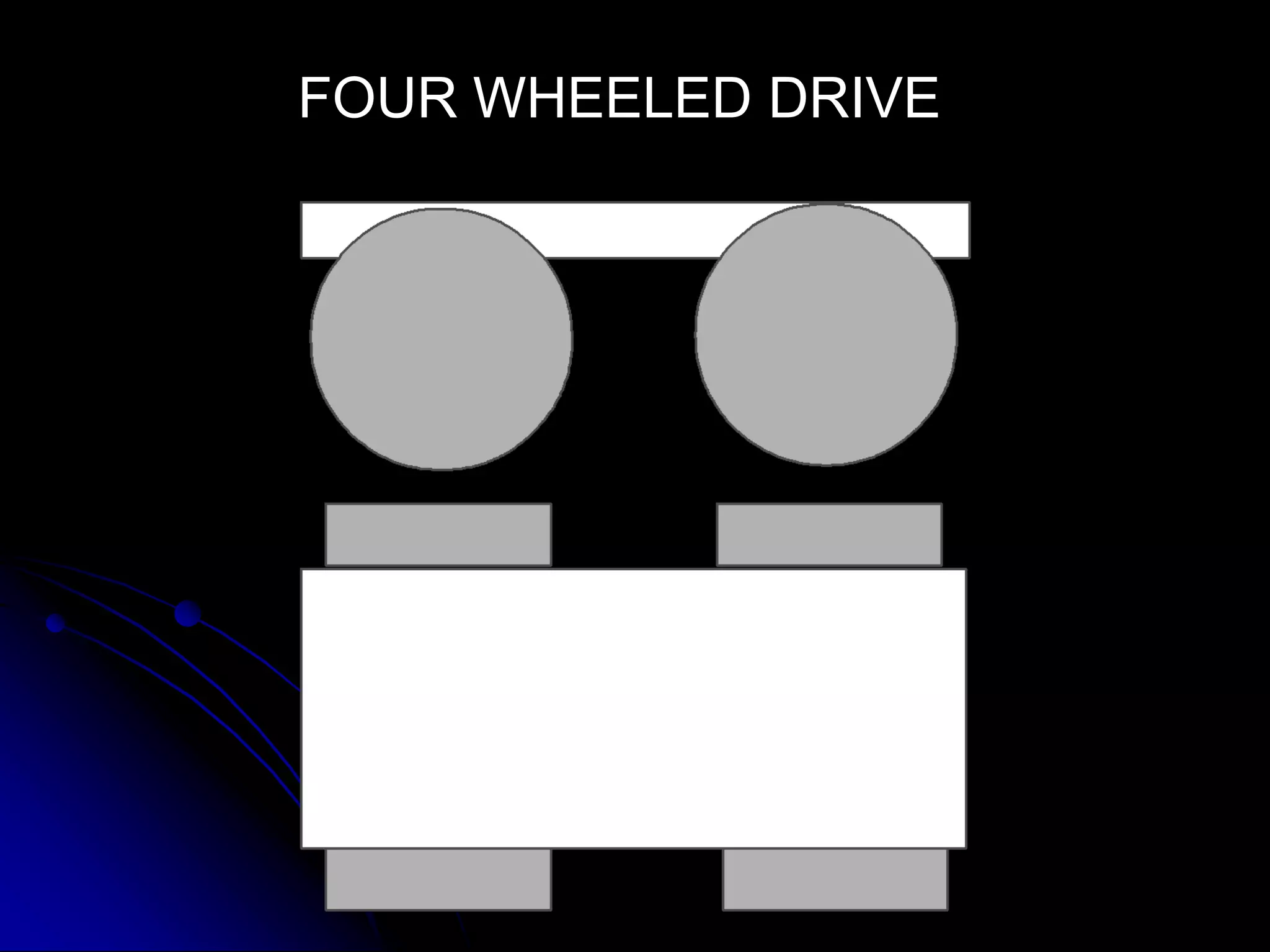
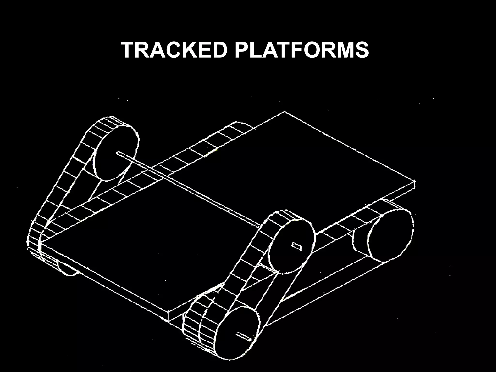
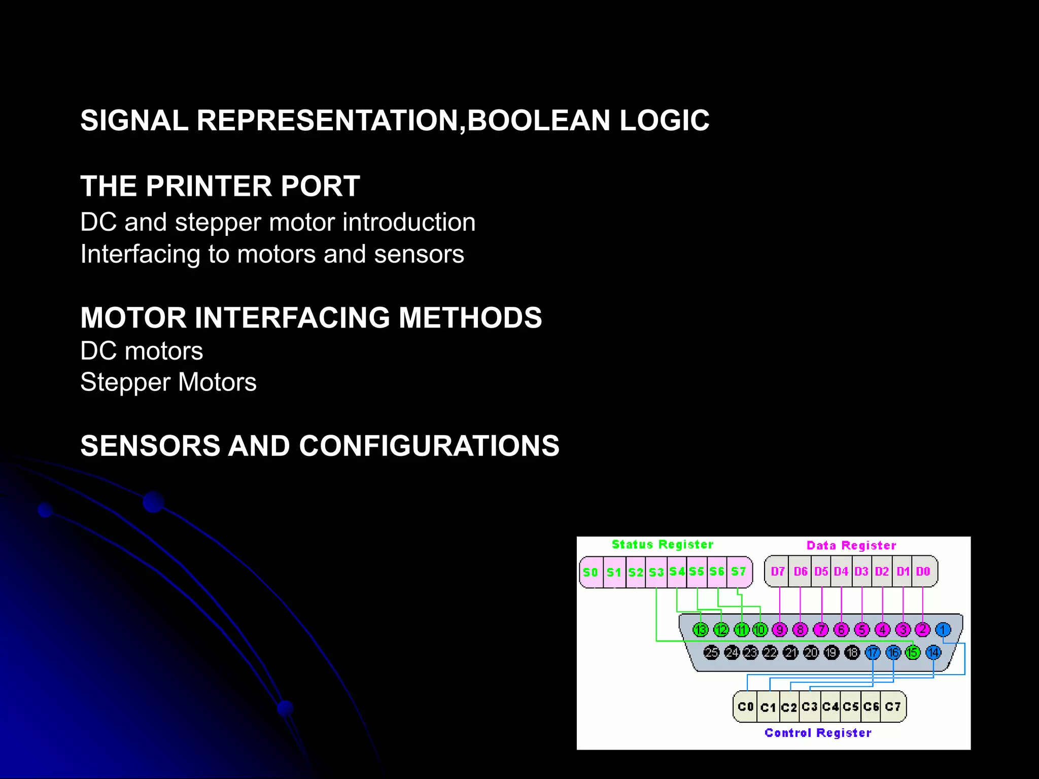
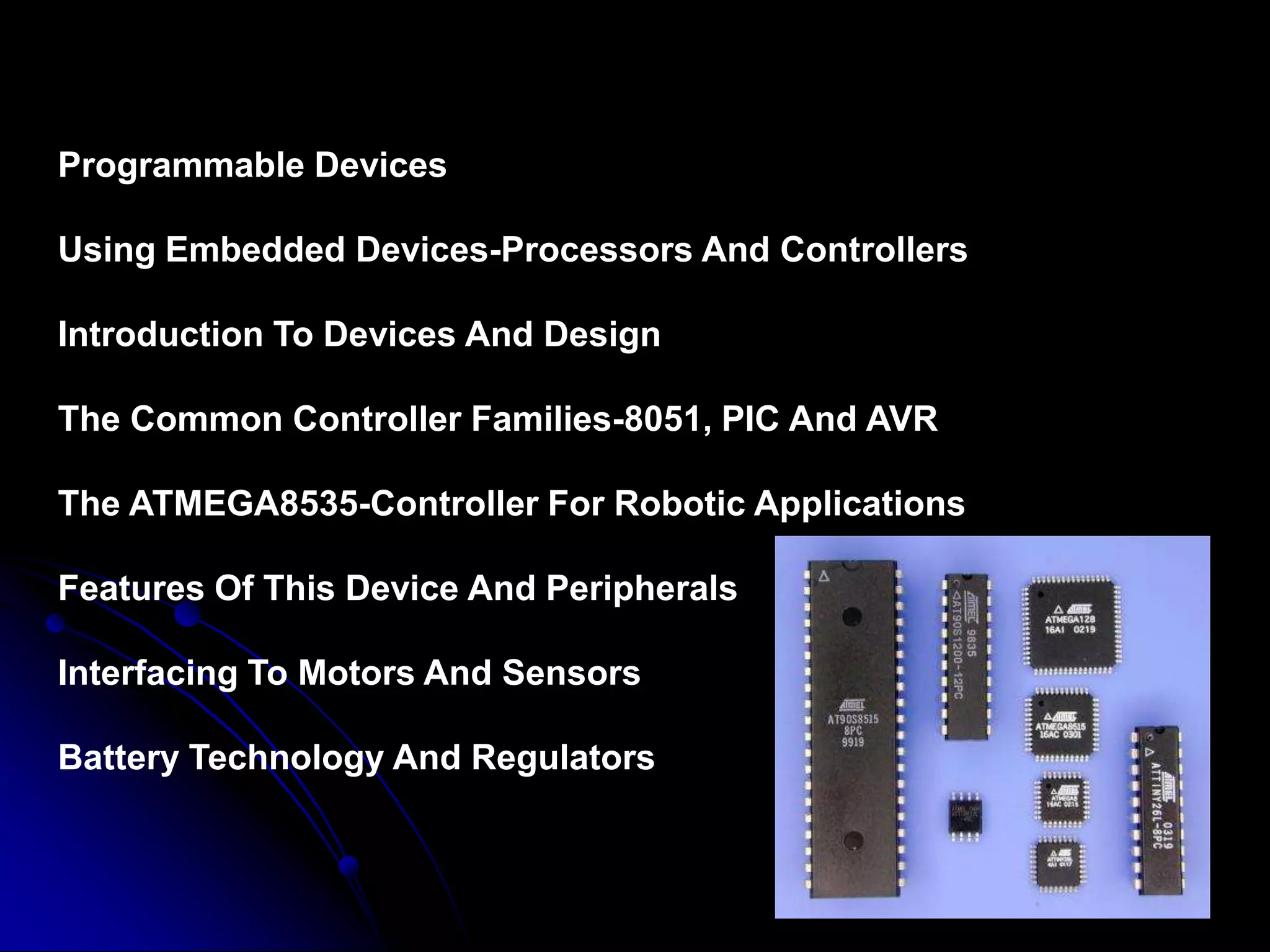
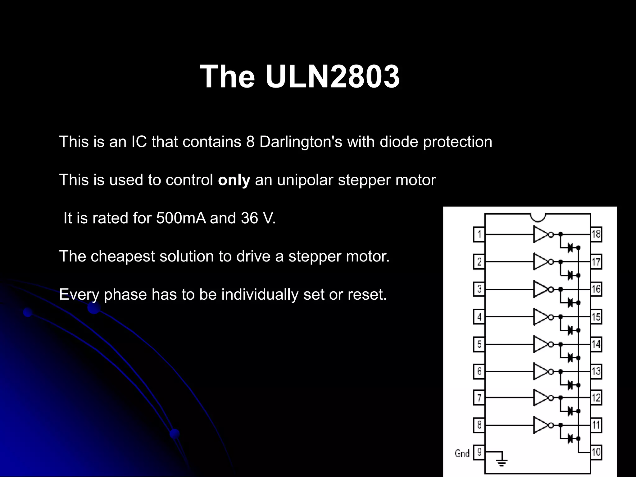
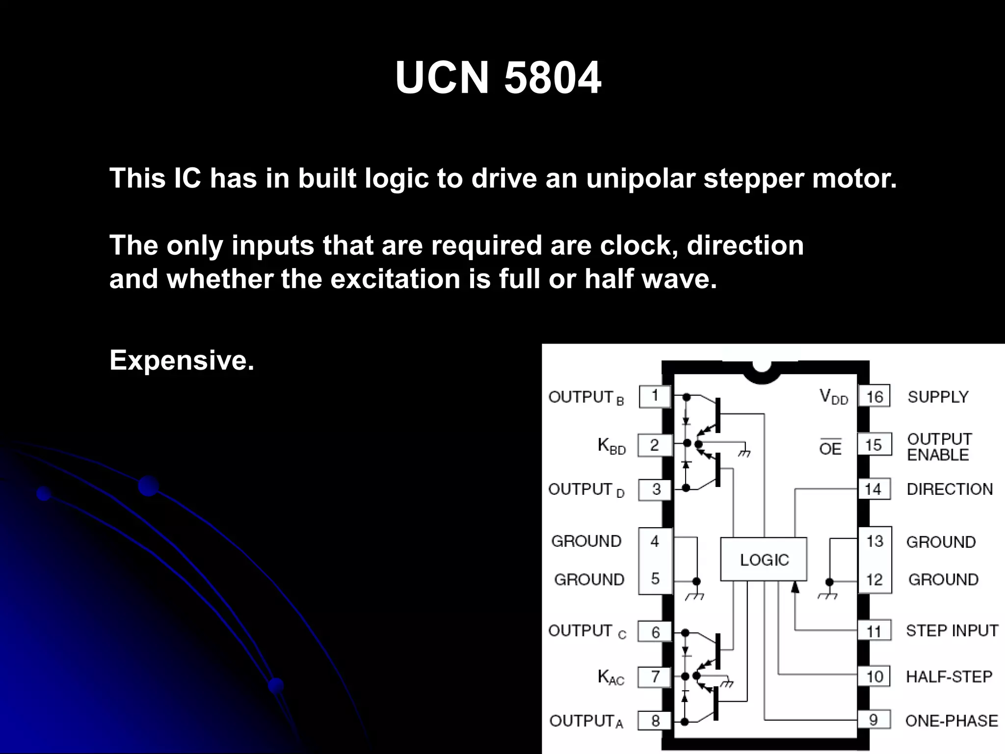
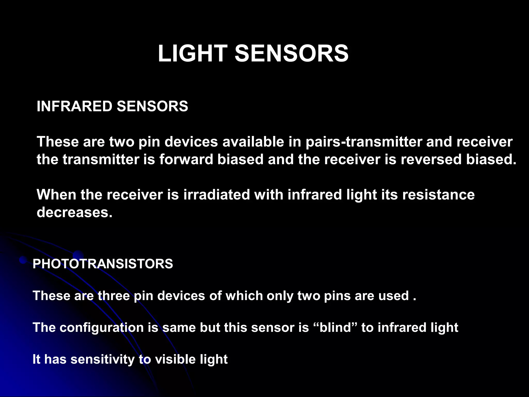
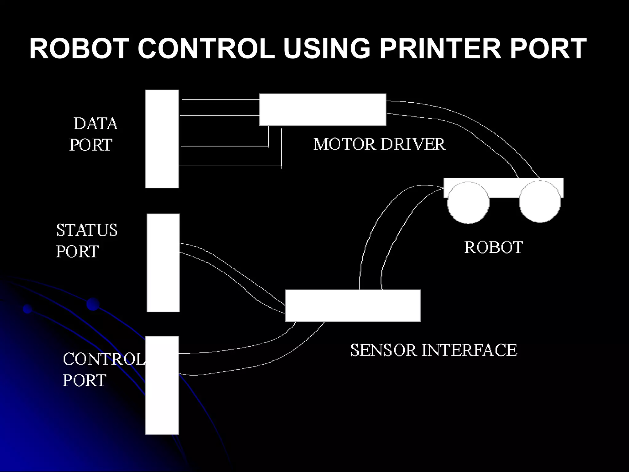
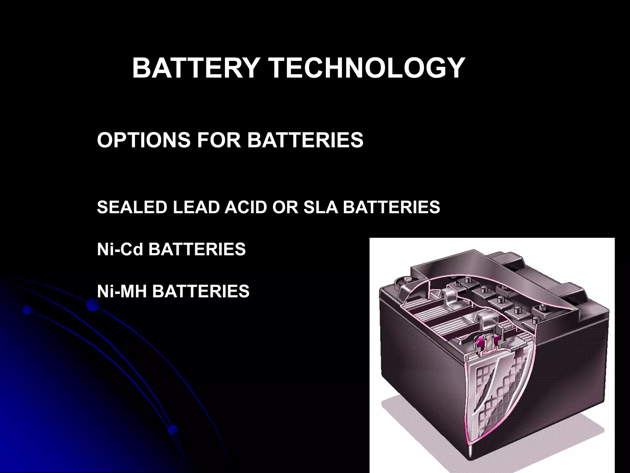
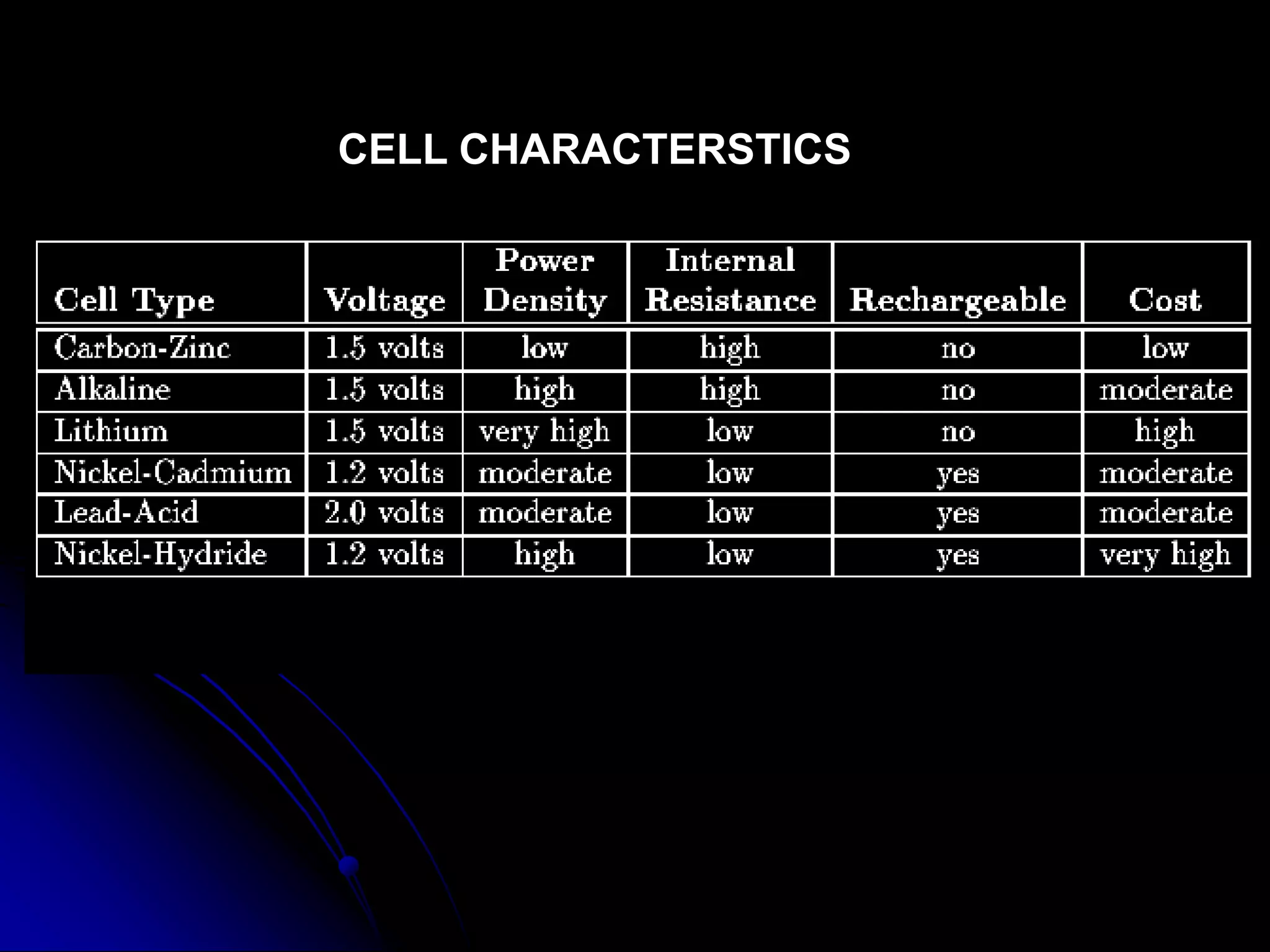
The document discusses various topics related to robotics including the Three Laws of Robotics, autonomous robots, robot chassis design, actuators like motors and wheels, materials for building robots, microcontrollers, battery technology, and voltage regulators. It provides information on different motor and sensor interfacing methods as well as programming microcontrollers to control robots.
The document describes the components, working, and applications of a line following robot. It consists of the following key components: IR sensors to detect the line, an Arduino UNO microcontroller, an L293D motor driver IC, and two geared motors. The IR sensors detect the visual line on the floor and send signals to the Arduino, which uses the motor driver IC to control the direction of the two motors accordingly. The line following robot is able to follow the line path, make turns when detecting breaks in the line, and has applications in industrial automation.
This document describes the design and functioning of a light following robot. The robot uses light dependent resistors (LDRs) to sense light and an op-amp circuit to compare the light readings from the LDRs. When more light falls on one LDR, the op-amp output activates the corresponding transistor which drives the motor on that side, causing the robot to turn towards the light source. The robot aims to follow a light source such as a flashlight by moving its motors based on the LDR sensor readings processed by the op-amp circuitry. Applications include uses in street lights, alarms, and devices that adjust screen brightness based on ambient lighting.
A robotic arm consists of linked segments connected by movable joints, similar to a human arm. The end of the kinematic chain that can grip or otherwise interact with its environment is called the end effector. The range of reachable positions for the end effector is defined as the robot's workspace. Proper selection of motors at each joint is important to ensure the arm can handle expected torques without failing. Common types of robot grippers include vacuum, hydraulic, pneumatic, and magnetic options, each with strengths for different applications.
This document describes a line follower robot. A line follower robot is a machine that can follow a visible or invisible path. It uses sensors to detect the line and a microcontroller to determine movements to follow the line. Key components include a chassis, wheels, batteries, motors, and electronic circuitry. Line follower robots have applications in industrial automation and transportation. The robot must be able to navigate various environments and conditions while precisely tracking the line.
The document discusses the design of a line following robot, including the components needed such as sensors, a microcontroller, motor drivers and motors. It describes how the robot uses sensor input to determine its position relative to a dark line and control its motors to follow the line while avoiding obstacles. Potential applications are discussed as well as limitations and areas for improvement in the design.
The document describes an engineering design project by a group of students to build a line following robot. The group includes 5 students and their project is to build a robot that can follow a black line on a white surface using 7 infrared sensors. The robot will use a PIC16F877A microcontroller to process sensor input and control 2 motors. The group's circuit design includes panels for analog to digital conversion, microcontroller simulation, and motor control. The robot is able to navigate and make turns at intersections using the sensor arrangement and programmed logic in the microcontroller.
The document describes an edge-avoiding robot that uses infrared (IR) sensors to detect edges and avoid falling off surfaces. It works by emitting IR rays from sensor modules and detecting the reflected rays. If both sensors receive rays, it continues forward. If one sensor detects an edge and stops receiving rays while the other still does, the robot turns away from the edge. The robot's hardware components include an Arduino, motor driver, DC motors, IR sensors, and other parts. It also explains how the ultrasonic sensor, servo motor, and motor driver circuit work.
This document outlines a semester project to build a line-following robot. It will use discrete electronic components like light dependent resistors and transistors to sense a white line on a black surface and motors to maneuver along the line. The project will have modules for mechanical design, motor control, and light sensing. It provides details on the components, circuit design, team responsibilities, timeline and potential risks.
This document presents information on a line follower robot and object detector. It discusses the components of the robots, including the motherboard, motors, sensors and programming. The motherboard contains the microcontroller, voltage regulator, motor driver and other components. It then describes how a line following robot works using infrared sensors to follow a black line, and potential applications like delivery vehicles. Finally, it briefly mentions object detection robots and concludes with potential future applications of robotics technology.
A line follower robot detects and follows a line on the floor using sensors. It uses a microcontroller like the AT89S52 to process sensor input and control motors to stay on the line. The hardware includes a power supply, sensors, motors, and other components. An embedded system combines both hardware and software to perform tasks. Line follower robots are used in manufacturing for transporting items between processes.
A line follower robot is designed to follow a predetermined path marked by a physical line or other markers. Various sensing schemes can detect these markers, ranging from simple low-cost line sensors to complex vision systems. Line follower robots are commonly used in manufacturing plants to move along specified paths and pick up and place components. They work by using sensors to detect the line path and feedback mechanisms to stay on course while correcting deviations.
This robot follows a black line on a bright surface or white line on a dark surface using IR sensors to detect the line. It uses a microcontroller, IR sensors, motor driver, and DC motors to sense the line and drive the wheels to stay on the line. When the sensors detect the line on one side, the microcontroller stops that side's motor to turn the robot.
These slides have been made by the members of roboVITics club - The Official Robotics Club of VIT. It deals with the basic concepts related to making a Line Follower Robot.
For details, visit http://maxEmbedded.com/
http://robovitics.in/
This document is a term paper report submitted by Priya Hada, a 5th semester B.Tech student in Electronics and Communication Engineering at Amity University Rajasthan. The report is about a line follower robot and includes an introduction, hardware description, working procedure, software skills used, and conclusions. The introduction provides background on line follower robots and describes their use in industrial applications to transport materials along predetermined paths. The hardware section details the basic components used including an AT89C51 microcontroller, IR sensors, motor driver circuitry, and a power supply.
Visiable Light is a robot that can sense and follow light. A user can shine a flashlight at its front and Light Rover will respond by following the light source. Light Rover uses a microcontroller for processing the sensor readings and responds by controlling the motors. The robot is designed with two sensors in mind, a left and a right. So when more light is detected on the left side, the robot will move towards it by rotating the right motor forward and the left motor backwards. The robot will know to move forward when both sensors receive about the same (by a margin we specify) amount of light.
The robot has two bipolar motors attached to front wheels of the robot. While rear wheels do not have any motor attached to them. The robot has two sensors fixed at its front panel separated by sufficient distance. It has a power supply & microcontroller circuitry placed inside the Light Rover.
We wanted to build a sensing light robot because microcontrollers are natural devices for sensing and responding to events.
The document provides an overview of the key components and working principle of a line-following robot, including:
1) Sensory systems that collect information about the outside world using sensors like photoresistors. 2) A data processing and motor control system that interprets sensor input signals and decides how to drive the motors. 3) Drive systems like DC motors that implement the motor control signals.
The line-following algorithm determines the robot's direction based on where the line is detected by the sensors - forward if centered, left if left of center, and right if right of center. If no line is detected, the robot circles until it finds the line again.
voice control robot using arduino,Bluetooth module and android application to driving it forward , backward,turn right,turn left,stop or automatic work to avoid obstacles with ultra-sonic sensor fixed on servo motor to detect distance in forward,right and left.
This project report summarizes the design and working of a line follower robot. It discusses the components used including an LM324 comparator IC, AT89C51 microprocessor, L293D H-bridge motor driver, and IR transmitter and receiver. It explains how the IR sensors detect the line and the microprocessor controls the motors to follow the line by turning when sensors detect line edges. The working principle section describes the robot's line detection and movement logic in detail. Applications mentioned include industrial transport, automated vehicles, and museum tour guides.
This document is an obstacle avoiding car project report submitted by three students - Utkarsh Bingewar, Shubham Thakur, and Rupesh Rote - to partially fulfill their project requirements for a bachelor's degree in electronics and telecommunications engineering. The report describes the design and implementation of a robotic vehicle that uses an ultrasonic sensor and microcontroller to detect and avoid obstacles in its path by controlling two DC motors through a motor driver. Experimental results show the car is able to successfully detect and navigate around obstacles.
The document describes a proposal for a line maze solver robot project. It includes an introduction to line mazes, the objectives of the project to build an autonomous robot that can solve a line maze, and the key components and methodology. The robot will use 6 light sensors to detect the black line on a white surface and make decisions at intersections. It will use an Arduino microcontroller to process sensor input and control the motors. The first run will record wrong turns to avoid on the second run when it can solve the maze quickly.
The document describes a line follower robot that uses infrared sensors to detect and follow a black line on a white surface. It uses an L293d motor driver IC to control two DC motors and drive the wheels. An LM324 comparator IC compares the output of the IR sensors to a reference voltage to determine if the sensor is over the black line or white surface. The robot also uses an L7805 voltage regulator to maintain a constant voltage supply for the components. The robot is able to navigate tight curves by sensing the line with the IR sensors and maneuvering accordingly using the closed-loop control system.
The document summarizes key components of a mobile robot including locomotion systems, power supplies, actuators, sensors, and control systems. It describes specific sensors like light dependent resistors and comparators that provide feedback. It also discusses actuators like DC motors and how their speed and direction can be controlled through H-bridge circuits and pulse width modulation.
The document describes a line following robot project submitted by four students to the Department of Mechanical Engineering at Jagannath University, Jaipur. It includes an acknowledgment, index, and sections on the circuit diagram, sensors, microcontroller, motor driver, source code, problems encountered, and applications of line following robots. The overall goal of the project is to build a robot that can sense a line and maneuver to stay on course using feedback from infrared sensors and a microcontroller to control motors via a motor driver.
The document provides instructions for building a line following robot. It begins with an overview of the system components and block diagram. It then covers the implementation details such as sensor circuits to read the line, motor control circuits, and the algorithm used. Source code for the microcontroller is also included. Finally, it suggests possible improvements and lists relevant references and resources.
This document describes an edge-detecting robot that uses an ATMega8 microcontroller. The robot has IR sensors on the left and right sides that detect edges and cause the robot to turn in the opposite direction. When an edge is detected, the appropriate motor is turned on via a motor driver IC to turn the robot away from the edge. The IR sensors send signals to comparators and then the microcontroller which controls the motor driver IC and decides which motor to power based on sensor input.
Software architecture of wheeled mobile robotsDmitry Suvorov
This document summarizes the key aspects of software architecture for wheeled mobile robots. It discusses common architectures including those without an OS, with a real-time OS, and with an embedded OS. It also covers important components like motion control using PID regulators, localization using odometry and lidar, and motion planning algorithms like A* and RRT Connect. The document provides advantages and disadvantages of the different approaches.
Motion Control of Differential Wheeled Robots with Joint Limit Constraints (S...obijuan_cube
The motion of wheeled mobile robots is inherently based on their wheels' rolling capabilities. The assumption is that each wheel can rotate indefinitely, backwards or forward. This is the starting point for all motion control mechanisms of wheeled robots. In this paper, a new motion capability of differential mobile robots with limited wheel rotation capabilities is presented. The robot will be able to travel any distance and change its direction of movement even if its wheels can not rotate within more than a certain range of angles. The proposed solution is based on the bio-inspired controller principles used for modular and legged robots, in which oscillations are generated for achieving motion. A total of two oscillators, one per wheel, are enough to generate well-coordinated rhythms on the wheels to control the robot motion. The kinematics of this new type of mobile robot motion is presented, and the relation between the oscillator's parameters and the trajectory is studied. Experiments with real robots will demonstrate the viability of this new locomotion gait.
Smart Home System Using Android ApplicationSiju Xavier
The document describes a smart home system that uses an Android application for control. The system allows appliances to be controlled remotely through a Bluetooth connection to a main control board. The main components of the control board are a PIC microcontroller, Bluetooth module, relays, and sensors. The system was designed to be low-cost and user-friendly, allowing disabled individuals to easily control home appliances from an Android device.
1. The document discusses different types of wheels used in mobile robots including fixed wheels, centered orientable wheels, off-centered orientable wheels, and Swedish wheels.
2. It also covers various locomotion methods for mobile wheeled robots including differential drive, tricycle drive, synchronous drive, and Ackerman steering.
3. Kinematics models are presented for different robot configurations to describe the relationship between the robot's motion and control inputs.
An introduction to Autonomous mobile robotsZahra Sadeghi
This document provides an introduction and overview of autonomous mobile robots and various techniques used in their development, including:
- Simulation studies allow researchers to test robot behaviors without building physical robots.
- The Khepera robot is a small, low-cost platform that has been used widely in research due its modularity and accessibility.
- Fuzzy logic, neuro-fuzzy systems, evolutionary robotics, and genetic programming are some methods explored for developing autonomous robot control systems without explicit programming. Co-evolution and complex environments can generate more advanced robot behaviors.
This document describes a proposed wireless AI-based industrial security robot project. The objectives are to build a wireless robot for industrial applications with live audio and video streaming to monitor areas that are difficult for people to access safely. The proposed system uses various sensors like fire, smoke, intruder, humidity and temperature sensors along with a wireless camera and Zigbee transmission to an ARM processor-controlled robot. If any abnormalities are detected, an alarm is sent to a remote PC and mobile phone via GSM. The robot is expected to move autonomously and avoid obstacles while transmitting real-time video and alerts. This intelligent robot could help improve safety and efficiency in hazardous industrial environments.
This document discusses home automation through an Android mobile device. It describes a system where a Bluetooth module and relays are used to allow an Android phone to remotely control home appliances. The phone acts as the host controller, communicating with client modules attached to devices via Bluetooth. The system allows users to control lights, temperature and other electronics from their mobile device.
1) The document describes the design and development of a 6 degree of freedom robotic arm to perform tasks requiring precision and endurance.
2) The mechanical hardware includes links cut from wood and connected by bearings, gear boxes, and stepper motors. The electrical hardware uses an Arduino Mega microcontroller, power supply, drivers, relays, and diodes.
3) The software includes forward and inverse kinematic models to control the position and orientation of the robotic arm from the joint angles. Simulations were also developed and presented.
This document discusses several techniques to reduce cogging torque in permanent magnet motors, which is an undesirable effect that prevents smooth rotor rotation. It describes classical and innovative techniques to minimize cogging torque through varying motor geometry while maintaining running torque. Some techniques discussed are skewing stator/magnets, fractional slots per pole, modulating drive current, and using optinet with magnets. Several industrial applications of cogging torque control are mentioned, like conveyor belts, CNC machines, and motorized vehicle braking. The document provides theoretical and practical justification for different cogging torque reduction techniques.
This comprises of compact yet detailed description about basic robotics. It gives description about different components that make up a robot and gives an idea on how to become advanced in robotics with an easy, user-friendly start.
A workshop to introduce everyone to manual robots, autonomous robots and robotic circuits while delving into the world of IoT with fun quiz segments and prizes.
Presentation for unit V in Mechatronics excluding case study. Stepper motor, servo motor, design procedure, Traditional and Mechatronic design approach
This document describes a pick and place robot that includes a metal detector and image/video transmission capabilities. It discusses the components of the robot, including a power supply, microcontroller, motors, grippers, communication modules, and a metal detector. The robot can pick and place objects, detect land mines, and transmit images and video to identify detected objects.
This document describes an Arduino-based obstacle avoiding robotic car. The car uses an ultrasonic sensor to detect obstacles and a micro servo to allow the sensor to scan the environment. It includes a motor shield and DC motors to control movement. The Arduino board processes sensor readings and sends signals to move around obstacles. Components are powered by a 9V battery. The goal is to autonomously navigate environments without human intervention.
The document describes the design of an electronics and programming project for a minor project involving an Atmega32 microcontroller, H-bridge circuit, DC motors, and programming in AVR Studio 4 to control the movement and direction of the motors through switches and sensors. Electronic components include an Atmega32 microcontroller, crystal oscillator, resistors, capacitors, diodes, and switches to operate the motors and LEDs according to programmed instructions loaded onto the microcontroller. The goal is to build a differentially-driven programmable robot using a basic H-bridge circuit design to reverse the polarity of the DC motors to control forward and backward movement.
PREFAC
The main aim of the Project was to make a Robot which is controlled by any mobile phone. The Detection of the Signal is done in Several Steps. Firstly, the Input Signal is sent to DTMF, which processes the signal and sends the 4 bit output to ROM which gives output to the Motor Driver IC on specific 4 bit inputs and the Motor Driver IC powers the motors of the car accordingly.
The Surveillance System is one which is used for the purpose of security system in intrude areas. This system is designed to develop a video monitoring, capturing the image and to store video frames in SD (Secure Digital) memory mounted on the ROBOT for further verification.
A Silicon valley startup is building a surveillance robot that it hope will help security and law enforcement personnel detect trouble while remaining out of harm’s way.
Robot are essentially a self-contained tribute to the wonders of technology. The most advance models use fast computer processing, high- definition cameras, artificial intelligence.
This document provides an overview of robotics components including motors, motor drivers, sensors and power supplies. It discusses how DC motors work and are controlled, including how H-bridge circuits and pulse-width modulation are used for direction and speed control. It also describes various sensors like LDRs, bump detectors and shaft encoders that provide feedback. An example of a line following robot is presented to illustrate how optical sensors and control algorithms are used for navigation.
A robot requires sensors, a microcontroller, motors, and a power source. Sensors like LDRs and phototransistors provide input to the microcontroller. The microcontroller processes the input and controls actuators like DC motors through motor drivers. Stepper motors provide accurate movement but require more complex control sequences. The document discusses various sensors, motors, and motor interfaces that can be used to build an automated robot.
An Experiment with circular saw blade – SPIKE RobotIJERD Editor
Robotics is an art which comprises of technology which deals with the design, construction, operation, and application of robots as well as computer systems for their control, sensory feedback, and information processing. This work gives the reader detail information about the Spike Robot that was created with basic wired robotics concept but reserves the capability to perform many actions, possible modifications will surely be going to enhance that capability
This document provides an overview of the system design and implementation of a semi-autonomous badminton playing robot. It describes the mechanical, electrical, and software systems that were developed including the robotic arm, dispenser, power management, microcontroller, sensors, motor drivers, and controls software. The overall goal was to develop an efficient robot that can compete in an annual competition by playing doubles badminton matches autonomously.
This document discusses the development of a microcontroller-based driver for stepper motors to control robotic movements and precision. It describes using an AT89c51 microcontroller to control a ULN2003 stepper motor driver through darlington pairs for high current gain. The driver allows precise control of stepper motors for applications in robotics, manufacturing, and other fields.
This document discusses the development of a microcontroller-based driver for stepper motors to control robotic movements. It describes using an AT89c51 microcontroller and ULN2003 driver chip to control a stepper motor through darlington pairs for high current gain. The driver allows precise control of stepper motors for applications in robotics, industry, and other fields.
A basic robotics workshop conducted for juniors at BIT Mesra in 2007. The presentation gives an overview of hobby robotics and necessary know how to get started building a robot.
This document discusses types of motors and motor controllers commonly used in robotics. It describes brushed DC motors, which are inexpensive and widely used in robots. A motor controller acts as an intermediary between a microcontroller and motor, providing the necessary current and voltage while taking instructions on motor control from the microcontroller. H-bridge motor controllers allow controlling both the speed and direction of DC motors by reversing current flow. The document provides details on brushed DC motor components and functioning, and how pulse-width modulation can be used to vary motor speed through a motor controller.
This document provides information about stepper motors, microcontrollers, and a stepper motor control project. It includes:
1) An overview of stepper motor types (permanent magnet, variable reluctance, hybrid), construction, and principles of operation. Stepper motors provide precise rotational control through discrete steps.
2) Details about the AT89C51 microcontroller used in the project, including its features and architecture. Microcontrollers integrate CPU and memory on a single chip for embedded control applications.
3) A description of the stepper motor control circuit using an AT89C51 microcontroller. The circuit allows controlling a DC stepper motor's rotation in clockwise and counterclockwise directions.
Automotive Engine Valve Manufacturing Plant Project Report.pptxSmith Anderson
The report provides a complete roadmap for setting up an Automotive Engine Valve. It covers a comprehensive market overview to micro-level information such as unit operations involved, raw material requirements, utility requirements, infrastructure requirements, machinery and technology requirements, manpower requirements, packaging requirements, transportation requirements, etc.
2. WHAT IS A ROBOT
The Three Laws Of Robotics
(ISAAC ASIMOV)
A robot may not injure a human being, or, through inaction,
allow a human being to come to harm.
A robot must obey the orders given it by human beings
except where such orders would conflict with the First Law.
A robot must protect its own existence as long as such
protection does not conflict with the First or Second Law.
3. An autonomous robot is simply a self-contained robot
that receives no assistance from outside, not even power.
WHAT IS AN AUTONOMOUS ROBOT
4. THE BUILDING BLOCKS OF A ROBOT
Mechanical Blocks
Electronics
Computer Code Or Firmware
Intelligence
Shall we start …
5.
6. CHASSIS DESIGN
ACTUATORS
MOTORS-DC AND STEPPERS
WHEELS
CASTORS
MATERIALS FOR CHASSIS DESIGN AND TOOLS
WEIGHT AND POWER CONSIDERATIONS
BUILDING SMALL ROBOTS
11. ACTUATORS
An actuator is a transducer that will convert one form
of energy to mechanical movement.
For example a motor, hydraulic cylinders, solenoids etc
12. MOTORS
A motor converts electrical energy to rotational movement.
TYPES OF MOTORS USEFUL FOR A ROBOT
DC MOTORS
STEPPER MOTORS
13. Consists of two wires externally.
Turn clockwise or anticlockwise when either wire
is at a higher potential than the other.
Normally have to be geared to provide working torque.
Robots that work autonomously should restrict
speeds over 100 rpm for driving motors.
More In The Electronics' Part Of Dc Motors…
14. These are motors that rotate in steps up on an
external command.
Excellent when accurate positioning is required.
Have very minimal torque and hence design
of the robot becomes critical
But are a good alternative to DC motors
They can consume larger currents as compared to DC
motors of comparable sizes.
More In The Electronics' Part Of Steppers…..
15. The next most important part of the robot is its wheels.
Wheels determine the pulling force of the robot, its speed, and
actually its height.
A back of the hand formula is that the larger the wheel the lower
the available force and higher the speed.
Select the lowest possible wheel diameter for the task at hand
16. The simple calculation comes from the torque formula
F=r x T
So a larger wheel calculates to a high speed but a low pulling force
17. WHEEL MATERIALS
Aluminium
Advantages
Looks very professional and robot looks neat.
Highly load bearing and stiff
Does not get corroded easily and will not sag or swell like wood.
Disadvantages
A little bit expensive but wheels last long.
Slightly difficult to work with and hence have to be machined
(actually bad when things fall off on last day)
Slightly heavy and have to be spoked to reduce weight.
18. NYLON
Advantages
Gives a clean look
Load bearing and stiff
Does not get corroded easily and will not sag or swell like wood.
Affordable and light weight.
Has to be machined
20. CASTORS
A castor is a free wheel that can rotate in any
direction in one plane
A castor is a wheel that normally attached to trolleys,
cabinets etc.
Such a wheel provides a third point of balance in tricycle
type chassis and turns in any direction thus allowing
smooth turns
21. MATERIALS FOR CHASSIS DESIGN
ALUMINIUM
Available in various cross sections.
Can be easily visualised in the requisite shape.
But can be time consuming and demanding to cut, drill and bend.
Chassis is very lightweight and durable.
22. ACRYLIC
Available in sheets of various thickness and sizes.
Can be cut, drilled very easily.
Cheap material for good design.
Brittle and not very strong.
Leaves irritating shavings after work.
23. TOOLS
Hacksaw for both wood and metal.
Small bench vice.
Hand drill with standard bit sizes.
Other tools like hammer, pliers ,spanners etc
25. SOME ADVICE
Mechanic assemblies are a one time investment
Build and machine good wheels and a stiff chassis
The best design is a two motor configuration with two
castors as front wheels
Choose the smallest diameter possible.
The alignment should be very accurate and the robot should not be
correcting itself every time because of misalignment.
Motors have to be dead straight.
Always this is achieved by a professional turner.
Weight of the robot should be as low as possible.
26.
27.
28. SIGNAL REPRESENTATION,BOOLEAN LOGIC
THE PRINTER PORT
DC and stepper motor introduction
Interfacing to motors and sensors
MOTOR INTERFACING METHODS
DC motors
Stepper Motors
SENSORS AND CONFIGURATIONS
29. Programmable Devices
Using Embedded Devices-Processors And Controllers
Introduction To Devices And Design
The Common Controller Families-8051, PIC And AVR
The ATMEGA8535-Controller For Robotic Applications
Features Of This Device And Peripherals
Interfacing To Motors And Sensors
Battery Technology And Regulators
30. SIGNAL REPRESENTATION
AND BOOLEAN LOGIC
Boolean logic is a branch of study that deals with quantities
represented by either yes(1) or no(0).
All decimal numbers can be broken down to digital numbers by using
base 2 computation.
In terms of voltages we assign 5V as logic 1 and 0V as logic 0 in
digital electronics.
31. THE PRINTER PORT
The printer port is a 25 pin female connector found on most
modern computers.
It is possible to command the printer port to set (1)or reset (0)
certain pins by writing a program on the computer. Such pins are
called output pins
It is also possible to read the value of certain pins on the port and
these can also be read by program. Such pins are called input pins
So if we configure the motors to be connected (via a motor driver) to
the output pins and sensors to input pins, and use a certain logic to
control the motors depending on the sensor values, it is possible to
control a robot whose parts are those sensors and motors.
33. OUTPUTTING VALUES FROM THE PORT
The data port is used as the output port.
The address of the data port is 0x378(base) on most computers.
In C if a command like
Outportb(0x378,4); // base=0x378
Is executed then the value of data port pins will be
(0 0 0 0 0 1 0 0) // binary for 4
34. INPUTTING VALUES FROM THE PORT
There are two input ports on the printer port
status port (base+1) and control port (base+2)
Both have less than 8 pins as inputs and have to be
used in conjunction for more inputs (upto 8)
A statement like
int c;
c=inportb(0x379); // 0x379=base+1
Will read the status port and store the read value in
variable c
35.
36. DRIVING MOTORS
The H-bridge
The H-bridge is a transistor based circuit that can input digital
logic value and switch a connected motor clockwise or anticlockwise.
37. If switches A and D are on then current flow from the supply ,
Switch A ,coil, switch D and ground.
If switches B and C are on then current flow from the supply ,
Switch B ,coil, switch C and ground.
38. THE L293 AND L298
Both these integrated circuits are two H-bridges in a single package.
They have 4 signal inputs that select witch transistor is on and 4
output pins to which we connect motors
Other pins include digital power, motor power, GND pins, inhibit
pins and current limit pins.
L293 is available in DIP package so has a rating of 1 AMP for both
bridges collectively.
The L298 is a beefy version and can have a total rating of 2 AMPS with
a heat sink to be connected externally.
40. STEPPER MOTORS
TYPES OF STEPPER MOTORS
Unipolar Motors(5 Wire Or 6 Wire)
Bipolar Motors(4 Wire)
All the above motors just about have the same internal windings
but the difference come in the way they are driven
Unipolar motors can be driven by either discrete transistors or H
bridges
Bipolar motors are exclusively driven by H-bridges
41. A stepper motor has four phase windings named
A B C D
When a phase is excited it means that that
phase has current flowing through it
A particular phase sequence imparts rotation
to the motor
The two excitation sequences are
HALF WAVE AND FULL WAVE
42. HALF WAVE EXCITATION
The phase sequence for a particular direction of rotation is
A-B-C-D-A-B-C-D-A-B …………
To reverse the direction of rotation the sequence is
D-C-B-A-D-C-B-A ……..
FULL WAVE EXCITATION
The phase sequence for a particular direction of rotation is
A- AB- B- BC- C- CD- D- DA- ……
To reverse the direction of rotation the sequence is
D- CD- C- BC- B- AB- A- ……
43. The ULN2803
This is an IC that contains 8 Darlington's with diode protection
This is used to control only an unipolar stepper motor
It is rated for 500mA and 36 V.
The cheapest solution to drive a stepper motor.
Every phase has to be individually set or reset.
44. UCN 5804
This IC has in built logic to drive an unipolar stepper motor.
The only inputs that are required are clock, direction
and whether the excitation is full or half wave.
Expensive.
45. SPEED CONTROL OF MOTORS
DC MOTORS
Speeds of dc motors can be controlled by using
Pulse width modulation or PWM
STEPPER MOTORS
Speed control can be done by changing the time
Interval between two successive steps.
46. SENSOR INTERFACING
The types of sensors are
Active and Passive
Depending on the type the configuration of the sensor
changes
For passive sensors the most common configuration is of a
potential divider.
47. LIGHT SENSORS
INFRARED SENSORS
These are two pin devices available in pairs-transmitter and receiver
the transmitter is forward biased and the receiver is reversed biased.
When the receiver is irradiated with infrared light its resistance
decreases.
PHOTOTRANSISTORS
These are three pin devices of which only two pins are used .
The configuration is same but this sensor is “blind” to infrared light
It has sensitivity to visible light
51. MICROPROCESSORS AND
MICROCONTROLLERS
A microprocessor is a device that does sequencing of
instruction that is written to its associated memory.
A microcontroller is same as a microprocessor but has its
memory and other peripherals associated with it in a single IC
package.
We will concentrate on microcontrollers but will dwell a little bit
into microprocessors.
Example 8085
52. COMMON MICROCONTROLLER
FAMILIES
8051
First microcontroller to be launched.
Very used and hence lots of programming resources.
8051 derivatives are also available with multiple
Features.
Not a good choice for robotics applications.
Messy programming interface.
Still in use today for embedded applications.
53. PIC-PERIPHERAL INTERFACE CONTROLLER
Good microcontroller family
Programming resources also available
Programmer mode is ICSP (In Circuit Serial Programmer)
One programmer fits all devices
Available in variety of cost and features
Suited for small robotic applications.
Never used it !!!
54. FEATURES OF ATMEGA8535
8 bit microcontroller with RISC architecture
On board 10 bit 8 channel ADC with highest sampling upto
15 kHz
Onboard UART with independent receive and transmit
registers
4 ports with high drive capability
8kb of on chip flash memory with ISP programmability
One programmer fits all devices
512 byte of SRAM and 512 bytes of EEPROM
3 timers with PWM function
58. VOLTAGE
REGULATORS
These are three pin devices whose output voltage is approximately a
constant over a large range of input conditions.
The 78XX series of voltage regulators is popular. The XX stands for
the output voltage that a certain device will deliver. For e.g.
A 7805 voltage regulator will deliver output voltage at 5 volts.
These devices at least need input voltage about 2 volts
higher than the output.
A 7805 regulator is required to provide constant voltage for
logic circuitry.