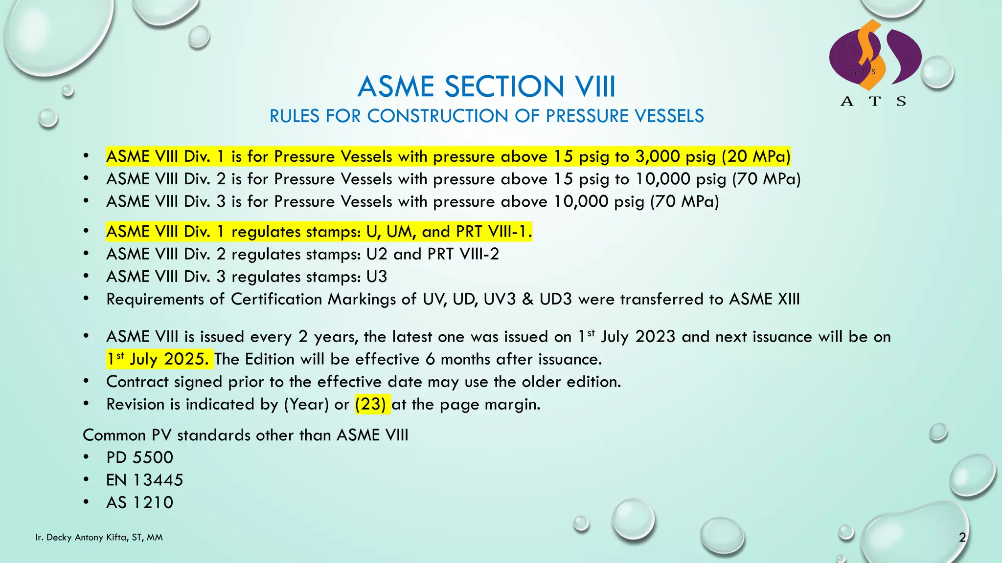
This document provides an introduction and overview of ASME Section VIII Division 1, which establishes rules for the construction of pressure vessels with pressures above 15 psig up to 3,000 psig. It discusses the scope and applicability of ASME VIII Div. 1, as well as key requirements for materials, fabrication, inspection, testing, and marking of pressure vessels. The document outlines requirements in areas such as material traceability, defect repair, forming, dimensional tolerances, impact testing, heat treatment, hydrostatic testing, and required marking of pressure vessels.
![[U-1] Vessels/pressure parts excluded from the scope are:
• Piping components (pipe, flange, fittings, valves, etc.)
• Vessels having an internal or external pressure not exceeding 15 psig.
• Vessels having inside diameter, width, height or cross-sectional diagram not exceeding 6-in.
• Pressure vessels for human occupancy.
• Vessels having design pressure exceeding 3,000 psig.
[U-1(j) The requirements of UM pressure vessels.
ASME SECTION VIII DIV. 1
[U-2] User’s Design form and involvement of RPE is required when below conditions are design requirements:
• Superimposed static reactions
• Cyclic or dynamic reactions
• Loadings due to wind, snow or seismic reactions
• Impact reactions
• Temperature effects
• Abnormal pressures
[U-4] Units of Measurements
• U.S. Customary, SI, or any local customary units may be used to demonstrate compliance with
requirements of this edition related to materials, fabrication, and overpressure protection, however, only
one or single system of units shall be used for all aspects of design except otherwise permitted by this
Division.
5
Ir. Decky Antony Kifta, ST, MM](https://image.slidesharecdn.com/introductiontoasmeviiidiv1ats-230705041220-f89f539f/75/Introduction-to-ASME-VIII-Div-1-ATS-pdf-5-2048.jpg)

![ASME SECTION VIII DIV. 1
[UG-4] General:
• Materials used shall conform with ASME Sect II Part D
• ASTM materials may be used provided conforming to
ASME Sect II Part A, Table II-200-1, i.e. within the
year specified in the table. This is also applicable for
SB materials.
[UG-10]
• Material identified with a specification not permitted by
this division and identified to a single production lot as
permitted by a permitted specification may be accepted
provided documentation is provided to the pressure
manufacturer that all applicable chemical and mechanical
properties meeting the permitted specification. When no
documentation is available the PV manufacturer can
perform chemical analysis and mechanical test and the
results are compared with a permitted specification.
[UG-5] Plate, [UG-6] Forgings, [UG-7] Castings, [UG-
8] Pipe and Tubes, and [UG-9] welding materials
7
Ir. Decky Antony Kifta, ST, MM
[UG-10] Cont’d.
• Pressure vessels manufacturer may re-certify and
mark the materials to the permitted specification.
• Material without identification shall not be used.](https://image.slidesharecdn.com/introductiontoasmeviiidiv1ats-230705041220-f89f539f/75/Introduction-to-ASME-VIII-Div-1-ATS-pdf-7-2048.jpg)
![ASME SECTION VIII DIV. 1
[UG-11] Prefabricated and preformed items may be
produced by other than PV manufacturer without a
certification mark as long as no permanent welding involved.
Permanent welding including weld overlay, except for
welded shell, heads or QOC, may be subcontracted to non-
ASME stamped shop provided the requirements specified in
this section are satisfied (UG-11(e).
[UG-12] Bolts & Studs, [UG-13] Nuts & Washers, [UG-14]
Rods & Bars, [UG-15] Product Specification
[UG-16 to UG-34] Design Issues (not discussed) except UG-
20(f) below
8
Ir. Decky Antony Kifta, ST, MM
[UG-20(f)] Impact test exemption for P-1
materials
• Impact test per UG-84 is not mandatory
for PV materials satisfying the bellow:
• The material shall be limited to P-1 gr. 1
& 2 and thickness shall not exceed:
• 13 mm materials for curve A
• 25 mm materials for curve B
• The PV shall be hydro-tested & designed
temp. Shall be from -29 to 345 °C.
[UG-35] Other Type of Closures
• Dished Covers (Dished head with bolting flanges)
• Quick Actuating Closures
• Quick Opening Closures (QOC) [UG-36 to UG-53] Design Issues (not discussed)](https://image.slidesharecdn.com/introductiontoasmeviiidiv1ats-230705041220-f89f539f/75/Introduction-to-ASME-VIII-Div-1-ATS-pdf-8-2048.jpg)
![ASME SECTION VIII DIV. 1
[UG-54] Supports:
All vessels shall be supported, and the supporting members shall be attached to withhold maximum imposed
loadings.
[UG-55] Lugs for platforms, ladders, and other attachments to vessel walls
Lugs or clips may be welded, brazed, or bolted to the outside or inside of the vessel support ladders,
platforms, etc.
[UG-76] Cutting plates and other stock
Plates, edges of heads, and other parts may be cut to shape and size by mechanical means such as
machining, shearing, grinding or by oxygen or arc cutting. After oxygen or arc cutting all slags and
detrimental discoloration shall be removed by mechanical means.
[UG-77] Material identification
The manufacturer shall maintain traceability of the materials to the original identification markings by either
or combination of: [1] accurate transfer of identification (heat no.), [2] use of coded marking (unique no.)
traceable to the original marking, [3] recording the material identification on the tabulation (traceability
sheet) or as built drawings which ensure that identification of each material during fabrication to vessel
completion.
9
Ir. Decky Antony Kifta, ST, MM](https://image.slidesharecdn.com/introductiontoasmeviiidiv1ats-230705041220-f89f539f/75/Introduction-to-ASME-VIII-Div-1-ATS-pdf-9-2048.jpg)
![ASME SECTION VIII DIV. 1
[UG-78] Repair of Defects in Materials
Defects in material may be repaired provided accepted by AI (Authorized Inspector)
[UG-79] Forming Pressure Parts
Shells or heads may be rolled or formed provided extreme fiber elongation (forming strains) are observed
and when required subsequent heat treatment shall be performed.
[UG-80] Permissible Out-of-Roundness of Cylindrical, Conical and Spherical Shells
The difference between the maximum and minimum inside diameters at any cross section shall not exceed
1% of the nominal diameter at the cross section under consideration.
10
Ir. Decky Antony Kifta, ST, MM](https://image.slidesharecdn.com/introductiontoasmeviiidiv1ats-230705041220-f89f539f/75/Introduction-to-ASME-VIII-Div-1-ATS-pdf-10-2048.jpg)
![ASME SECTION VIII DIV. 1
[UG-81] Tolerance for Formed Heads
The inner surface of head shall not deviate outside of the specified shape by more than 1-1/4% of D nor
inside of the specified the specified shape by more than 5/8% of D, where D is the nominal inside diameter
of the vessel shell at point of attachment.
[UG-82] Lugs & Fitting Attachments
[UG-84] Charpy Impact Test
• Test procedure to follow: ASME SA-370 or ISO 148
• Test specimen shall be as per Fig. UG-84 & Fig. UG-84.5
• Acceptance criteria shall be as per Fig. UG-84.1
• When impact test on production required one test plate shall be made for each welding procedure used
for Category A and B, however, when manufacturer uses same welding procedure for both categories,
only Category A can represent the test plate. [UG-84(i)(1) – (3)].
• For production weld impact test, the test to be performed on weld metal and heat affected zone.
[UG-85] Heat Treatment
Heat treatment of plate may be performed by PV manufacturer
11
Ir. Decky Antony Kifta, ST, MM](https://image.slidesharecdn.com/introductiontoasmeviiidiv1ats-230705041220-f89f539f/75/Introduction-to-ASME-VIII-Div-1-ATS-pdf-11-2048.jpg)
![ASME SECTION VIII DIV. 1
[UG-90] Inspection and Tests: Manufacturer’s responsibility
(1) Maintain Certificate of Authorization
(2) Prepare drawings & design calculations
(3) Materials identifications used for
Construction
(4) Obtain Partial Data Reports (if any)
(5) Prepare access for the Inspector
(6) Examination of materials, materials
identification, and traceability.
(7) Document impact tests and other tests
(8) Concurrence of the Inspector prior to any
base metal repairs.
(9) Examination of heads & shells are properly
formed.
(10) Qualification of welding procedures
(11) Qualification of welders & welding
operators
(12) Examination of all parts prior to joining for welding
(13) Examination of parts for material marking, defects,
and dimensional geometry.
(14) Provisions of controls to ensure that all required
heat treatments are performed.
(15) Provisions of records of NDT including RT images.
(16) Making the required hydrotest or pneumatic test &
arranging witness by the Inspector.
(17) Applying the required stamping/ nameplate to the
vessel
(18) Preparing the required Manufacturer’s Data
Reports & certifying by Inspector
(19) Providing the retention of RT & UT reports
Manufacturer’s Data Reports and other records.
12
Ir. Decky Antony Kifta, ST, MM](https://image.slidesharecdn.com/introductiontoasmeviiidiv1ats-230705041220-f89f539f/75/Introduction-to-ASME-VIII-Div-1-ATS-pdf-12-2048.jpg)
![ASME SECTION VIII DIV. 1
[UG-93] Inspection of Materials
• Plates shall require materials test reports
• All other product forms can be accepted when the product has the correct marking of specification
including grade, type and class of the materials.
[UG-92] Inspection of Materials
• Manufacturer shall arrange free access to AI for performing inspection on PV.
[UG-91] The Inspector
• Individual employed by ASME Accredited Authorized Inspection Agency (AIA) as per ASME QAI-1.
[UG-94] Marking on Materials
• If the material identifying marks are obliterated or material is divided into two or more parts, the marks
shall be properly transferred by the Manufacturer.
[UG-95] Examination of surfaces during fabrication, [UG-96] Dimensional check of component parts & [UG-
97] Inspection During Fabrication.
13
Ir. Decky Antony Kifta, ST, MM](https://image.slidesharecdn.com/introductiontoasmeviiidiv1ats-230705041220-f89f539f/75/Introduction-to-ASME-VIII-Div-1-ATS-pdf-13-2048.jpg)
![ASME SECTION VIII DIV. 1
[UG-98] Maximum Allowable working pressure
• MAWP is the maximum pressure permissible at the top of the vessel in its normal operating position at
the designated coincident temperature specified for that pressure.
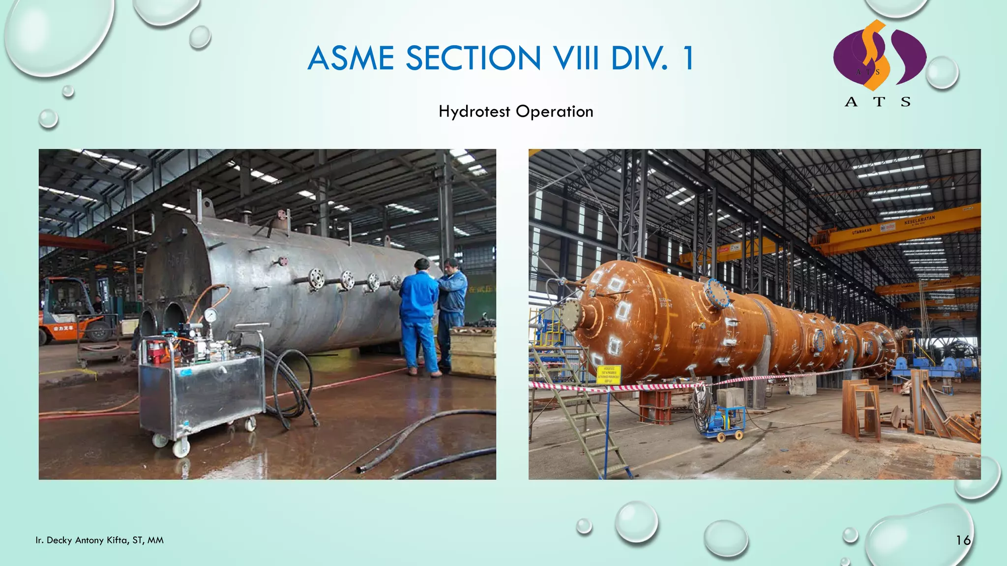
[UG-99] Standard Hydrostatic Test
• Vessels designed for internal pressure shall be subjected to a hydrostatic test pressure that at every point
in the vessel is at least equal to 1.3 x MAWP multiplied by LSR (Lowest Stress Ratio) for the pressure
boundary materials of which the vessel is constructed.
• The vessel shall not be hydrotested with paint or internal lining unless approved by user or his designated
agent.
• The minimum temperature during hydrotest shall be 17 °C warmer than MDMT and maximum test
temperature is 48 °C.
• Vessel with Lethal service shall not be painted or internally lined prior to hydrotest.
14
Ir. Decky Antony Kifta, ST, MM](https://image.slidesharecdn.com/introductiontoasmeviiidiv1ats-230705041220-f89f539f/75/Introduction-to-ASME-VIII-Div-1-ATS-pdf-14-2048.jpg)
![Ir. Decky Antony Kifta, ST, MM 15
[UG-100] Pneumatic Test
• Vessels shall be pneumatic tested that at every point in the vessel is at least equal to 1.1 x MAWP
multiplied by LSR (Lowest Stress Ratio) for the pressure boundary materials of which the vessel is
constructed.
• The vessel shall not be pneumatic tested with paint or internal lining unless approved by user or his
designated agent.
• The minimum temperature during hydrotest shall be 17 °C warmer than MDMT and maximum test
temperature is 48 °C.
• Vessel with Lethal service shall not be painted or internally lined prior to pneumatic testing.](https://image.slidesharecdn.com/introductiontoasmeviiidiv1ats-230705041220-f89f539f/75/Introduction-to-ASME-VIII-Div-1-ATS-pdf-15-2048.jpg)
![ASME SECTION VIII DIV. 1
[UG-101] Proof Tests to establish MAWP
• Where design rule do not exist in this Division therefore this proof test method to be performed [U-2
(g)(1)]
[UG-102] Test Gages
• Dial indicating pressure gage used in testing shall be graduated over a range of about doble the
intended maximum test pressure, but in no case shall the range be less than 1-1/2 nor 4 times that
pressure. Digital reading pressure gages having wider range of pressure may be used, provided the
readings give the same or greater degree of accuracy as obtained with dial pressure gage.
[UG-103] NDT
• MPI shall be performed as per Mandatory Appendix 6 and PT shall be as per Mandatory Appendix 8.
[UG-115] Marking and Reports
• The unit of measurement used in Manufacturer’s Data Reports (U Stamp), Manufacturer’s Certificates of
Compliance (UM Stamp) and capacity certification of pressure relief devices and in marking or stamping
pressure vessels, vessel parts and pressure relief devices, required by this Division, shall be either US
Customary Units or any local customary units and a single system of units shall be used for all aspects of
design [U-4(b)]
17
Ir. Decky Antony Kifta, ST, MM](https://image.slidesharecdn.com/introductiontoasmeviiidiv1ats-230705041220-f89f539f/75/Introduction-to-ASME-VIII-Div-1-ATS-pdf-17-2048.jpg)
![ASME SECTION VIII DIV. 1
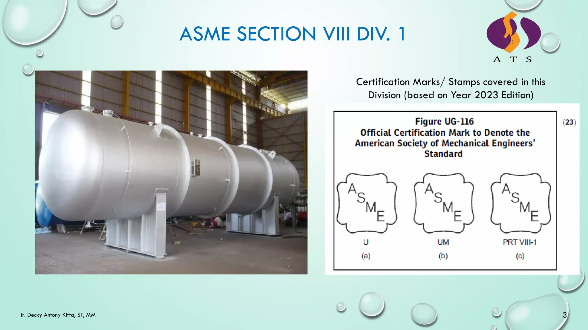
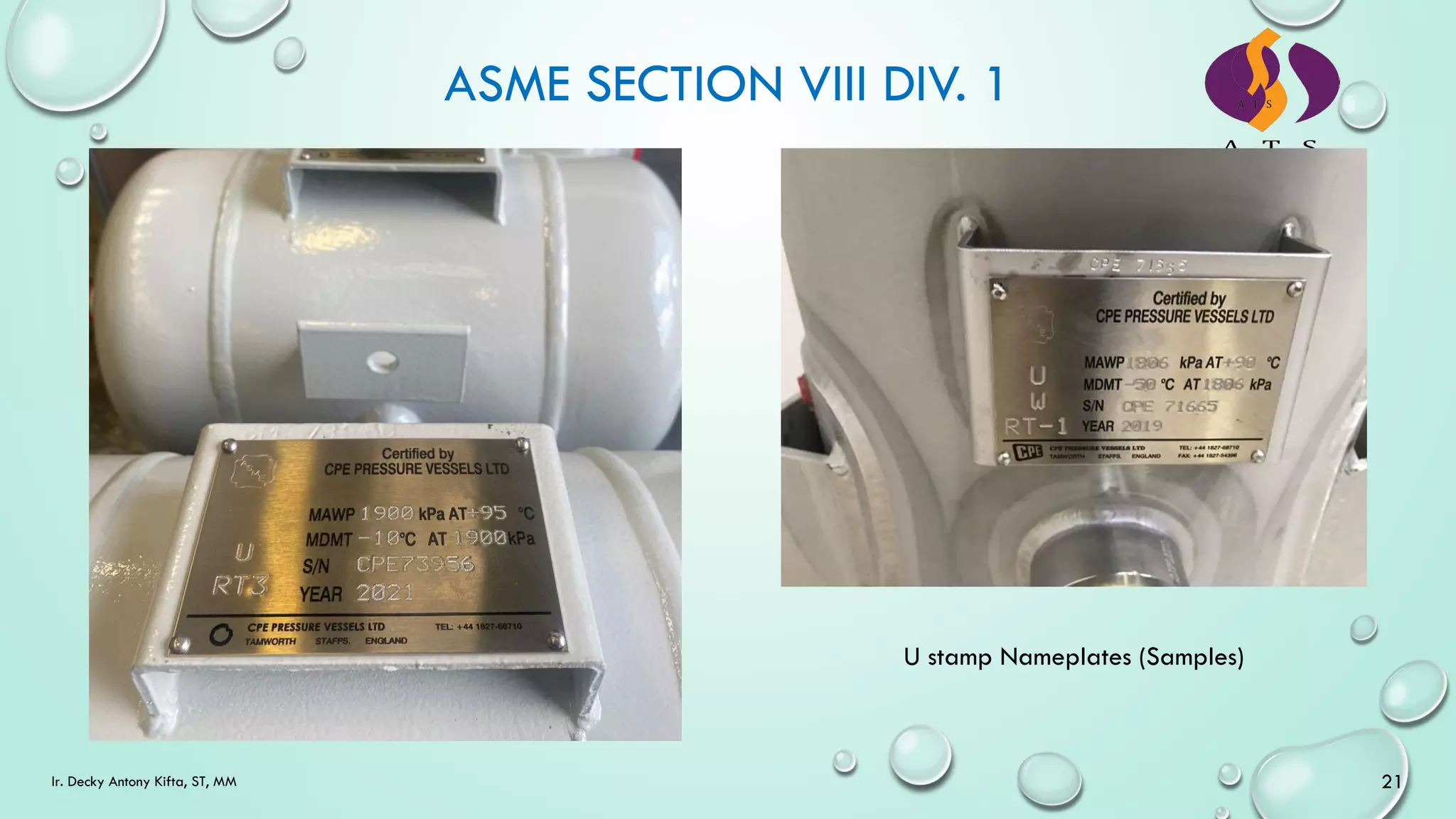
[UG-116] Required Marking
• Each PV shall be marked with the following
[UG-116] Required Marking
• When RT or UT examination has been performed
• RT-1 when all pertaining butt welds other than Category B and C butt welds associated with nozzles and
communicating chambers that neither exceeds NPS 10 nor 1-1/8 in. wall thickness satisfy the full RT
requirements for their full length [UW-11(a)]
18
Ir. Decky Antony Kifta, ST, MM](https://image.slidesharecdn.com/introductiontoasmeviiidiv1ats-230705041220-f89f539f/75/Introduction-to-ASME-VIII-Div-1-ATS-pdf-18-2048.jpg)
![ASME SECTION VIII DIV. 1
[UG-116] Required Marking (Cont’d)
• RT-2 when the complete vessel satisfies the
requirement UW-11(a)(5) (full RT on LS) and
when the spot radiography requirements of
UW-11(a)(5)(-b) (spot RT on circ seam which
intersect with LS) have been applied.
• RT-3 when the complete PV satisfies the spot RT
as per UW-11b.
• RT-4 when only part of the complete PV has
satisfied the RT [UW-11(a)] or where none of
the markings RT-1, RT-2 or RT-3 are applicable.
[UG-116] Required Marking (Cont’d)
• Parts of vessels for Which partial Data Reports
are required in UG-120 (c) shall be marked by
the manufacturer of the part, with a nameplate
or stamping, with the following:
• The U Designator shall stamp the word
‘PART’ below the Certification Mark.
• The PRT Designator shall stamp the name
of the manufacturer after/below the
words ‘certified by’ and the manufacturer’s
serial number. The word PART may not be
stamped.
19
Ir. Decky Antony Kifta, ST, MM](https://image.slidesharecdn.com/introductiontoasmeviiidiv1ats-230705041220-f89f539f/75/Introduction-to-ASME-VIII-Div-1-ATS-pdf-19-2048.jpg)
![ASME SECTION VIII DIV. 1
[UG-117] Certificates of Authorization and
Certification Marks
• UM Certification Mark is granted by the
Society and is used by the manufacturer
• UM Designator shall employ a Certified
Individual qualified to ASME CA-1 and meeting
the requirements of ASME QAI-1
• Certified Individual shall certify Form U-3, U-
3A or U-3P (Manufacturer’s Certificate of
Compliances)
• UM Designator shall already have S or U
certificate.
• UM certification is valid for 1 year but the 1st
and 2nd reviews can be done by AI and AI
Supervisor. The third review or joint review will
be performed after 3 years
• Any Manufacturer holding U, UM & PRT VIII-1
Certification marks shall have QC System
(Manual) as per Appendix 10 & ASME CA-1.
[UG-118 & 119] Methods of Stamping & Nameplate
• The required marking shall be applied by one of the
following methods:
• Nameplate
• Stamped directly on the vessel
• Electrochemically etched
20
Ir. Decky Antony Kifta, ST, MM](https://image.slidesharecdn.com/introductiontoasmeviiidiv1ats-230705041220-f89f539f/75/Introduction-to-ASME-VIII-Div-1-ATS-pdf-20-2048.jpg)
![ASME SECTION VIII DIV. 1
22
Ir. Decky Antony Kifta, ST, MM
[UG-120] Date Reports
• Manufacturer’s Data reports to be filled by U
Designator are:
• Form U-1, U-1A or U-1P (Plate Heat
Exchanger) and U-4 (attachment) when
required.
• Form U-5 for Fixed Tube Sheet Heat
Exchanger
• Manufacturer’s Certificate of Compliance to be
issued by UM Designator are:
• Form U-3, U-3A or U-3P
• Parts manufacturer shall fill in Form U-2 or U-
2A.
[UG-120] Date Reports (Cont’d)
• U Designator shall maintain the Manufacturer’s
Data Reports for at least 3 years
• UM Designator shall maintain the
Manufacturer’s Certificate of Compliance for at
least 5 years.
• Vessel (U or UM) to be registered to National
Board, the Manufacturer’s Data Reports or
Manufacturer’s Certificate of Compliance shall
be sent to National Board of Boiler and
Pressure Vessel Inspector in Ohio, USA.
[UG-150 to 156] regarding the pressure relieve valves or devices (not discussed)](https://image.slidesharecdn.com/introductiontoasmeviiidiv1ats-230705041220-f89f539f/75/Introduction-to-ASME-VIII-Div-1-ATS-pdf-22-2048.jpg)
![ASME SECTION VIII DIV. 1
24
Ir. Decky Antony Kifta, ST, MM
[UW-2] Service Restrictions
• PV contains lethal substances, all butt welds
shall be fully radiography
• When fabricated using carbon or low alloy
materials, PV shall be PWHT at any wall
thickness
• The meaning of lethal is liquid or gas that a
very small amount mixed or not mixed with air
is dangerous to life when inhaled.
[UW-3] Welded Joint Category
• Cat A = longitudinal welded joint (shell &
head) and circ seam shell to heads other than
the dished head.
• Cat B = circumferential welded joint
• Cat C = weld connecting flanges, flat head to
main shell.
• Cat D = weld connecting nozzles to main shells,
to heads](https://image.slidesharecdn.com/introductiontoasmeviiidiv1ats-230705041220-f89f539f/75/Introduction-to-ASME-VIII-Div-1-ATS-pdf-24-2048.jpg)
![ASME SECTION VIII DIV. 1
25
Ir. Decky Antony Kifta, ST, MM
[UW-5 & UW-6] Materials and Weld Consumables (not discussed)
[UW-8 & UW-9] Design (not discussed)
[UW-10] PWHT, refer to UW-40 and UCS-56 (for carbon and low
alloy steels)
[UW-11] Radiography and Ultrasonic Examination
• Full radiography to be performed on:
• All butt welds in the shell and heads of vessels to contain
lethal substances
• All butt welds in the shell and heads of vessels with
thickness exceed 1-1/2 in (38 mm) or for carbon and low
alloy steels as per Table UCS-57.
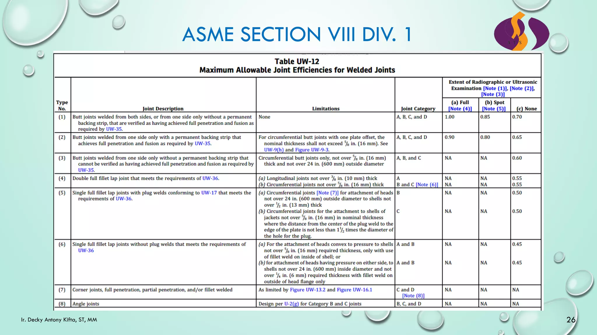
[UW-12] Joint Efficiencies
• Refer to Table UW-12 below
PAUT (Phased Array UT)](https://image.slidesharecdn.com/introductiontoasmeviiidiv1ats-230705041220-f89f539f/75/Introduction-to-ASME-VIII-Div-1-ATS-pdf-25-2048.jpg)
![Ir. Decky Antony Kifta, ST, MM 27
[UW-13] Attachment Details not designed
[UW-14] Openings in or adjacent to welds
• Single opening may be located in head-to-shell or Category B or C butt-welded joints, provided the weld
meets the radiographic requirements in UW-51 for a length equal to three times the diameter of the
opening with the center of the hole at midlength. Defects that are completely removed in cutting the hole
shall not be considered in judging the acceptability of the weld.
[UW-15 to UW-20] regarding design (not discussed)](https://image.slidesharecdn.com/introductiontoasmeviiidiv1ats-230705041220-f89f539f/75/Introduction-to-ASME-VIII-Div-1-ATS-pdf-27-2048.jpg)
![ASME SECTION VIII DIV. 1
28
Ir. Decky Antony Kifta, ST, MM
[UW-26] Fabrication
• Each manufacturer shall be responsible for the quality of the welding done by the organization
• All welding shall be performed in accordance with Manufacturer’s WPS in accordance with ASME IX.
• All welders shall be qualified by the manufacturer in accordance with ASME IX
• The manufacturer shall be responsible for Code compliance of the vessel or part, including Certification
Mark Stamping and providing Manufacturer’s Data Report Forms properly and countersigned by the
Inspector.
[UW-27] Welding Processes
• The welding processes that may be used in the construction of vessel are limited to those listed in ASME IX.
[UW-28] Qualification of welding procedure
• Each welding procedure used in joining pressure parts to pressure parts or joining pressure parts to load
carrying non-pressure parts, shall be recorded in detail by the manufacturer and qualified in accordance
with ASME IX.](https://image.slidesharecdn.com/introductiontoasmeviiidiv1ats-230705041220-f89f539f/75/Introduction-to-ASME-VIII-Div-1-ATS-pdf-28-2048.jpg)
![ASME SECTION VIII DIV. 1
29
Ir. Decky Antony Kifta, ST, MM
[UW-29] Tests of welders and welding operators
• The welders and welding operators used in
welding pressure parts and in joining load-
carrying non-pressure parts to pressure parts
shall be qualified in accordance with ASME
IX.
• Each welder and welding operator shall be
assigned an identifying number, letter, or
symbol by the manufacturer which shall be
used to identify the work of that welder or
welding operator.
• The manufacturer shall maintain a record of
the welders and welding operators showing
the date and results of tests and identification
mark assigned to each.
[UW-30] Lowest permissible temperature for
welding
• It is recommended that no welding of any
kind be done when the temperature of the
base metal is lower than -20 °C. At temp.
between 0 °C and -20 °C, the surface of all
areas within 75 mm of the point where a
weld is to be started should be heated to a
temp. at least warm to the hand (about 15
°C) before welding is started.
[UW-31] Cutting, Fitting, and Alignment
• When plates are shaped by oxygen or arc
cutting, the edges to be welded shall uniform
and smooth and shall be free of all loose
scale and slag accumulations before welding.](https://image.slidesharecdn.com/introductiontoasmeviiidiv1ats-230705041220-f89f539f/75/Introduction-to-ASME-VIII-Div-1-ATS-pdf-29-2048.jpg)
![ASME SECTION VIII DIV. 1
30
Ir. Decky Antony Kifta, ST, MM
[UW-32] Cleaning of Surfaces to be welded
• The surfaces to be welded shall be clean and
free of scale, rust, oil, grease, slag,
detrimental oxides, and other deleterious
foreign material.
[UW-33] Alignment Tolerance
• Alignment of sections at edges to be butt
welded shall be such that maximum offset is
not greater that the applicable amount for
the welded joint category under consideration
(Refer to Table UW-33).
• Any offset within the allowable tolerance
provided in the table above shall be faired
at a three to one taper over the width of the
finished weld, or if necessary, by adding
additional weld metal (buildup) beyond what
would otherwise be the edge of the weld.
Table UW-33
[UW-32] Finished Longitudinal and Circumferential
Joints
• Butt-welded joints shall have complete
penetration and full fusion. As-welded surfaces
are permitted, however, the surface of welds
shall be sufficiently free from coarse ripples,
grooves, overlaps, and abrupt ridges and
valleys to permit proper RT interpretation and
NDT inspections.](https://image.slidesharecdn.com/introductiontoasmeviiidiv1ats-230705041220-f89f539f/75/Introduction-to-ASME-VIII-Div-1-ATS-pdf-30-2048.jpg)
![ASME SECTION VIII DIV. 1
31
Ir. Decky Antony Kifta, ST, MM
[UW-32] Finished Longitudinal and Circumferential
Joints (Cont’d)
• Butt-welded joints shall have complete
penetration and full fusion. As-welded surfaces
are permitted, however, the surface of welds
shall be sufficiently free from coarse ripples,
grooves, overlaps, and abrupt ridges and
valleys to permit proper RT interpretation and
NDT inspections.
• Reduction in thickness shall not reduce the
material of adjoining surfaces below the design
thickness at any point.
• Reduction in thickness shall not exceed 1mm or
10% of the nominal thickness of the adjoining
surface, whichever is less.
• The thickness of the weld reinforcement on each
face shall not exceed the below table.
[UW-36] Fillet welds
• Fillet weld shall be deposited in such a way
that adequate penetration into the base
metal at the root of the weld is secured.](https://image.slidesharecdn.com/introductiontoasmeviiidiv1ats-230705041220-f89f539f/75/Introduction-to-ASME-VIII-Div-1-ATS-pdf-31-2048.jpg)
![ASME SECTION VIII DIV. 1
32
Ir. Decky Antony Kifta, ST, MM
[UW-37] Miscellaneous Welding Requirements
• Each welder and welding operator shall stamp
the identifying number, letter, or symbol
assigned by the manufacturer, on or adjacent to
and at intervals of the manufacturer, on or
adjacent to and intervals of not more than 1m
along the welds which he makes in steel plates
6mm and over in thickness and in nonferrous
plates 13mm and over in thickness; or a record
shall be kept by the Manufacturer of welders
and welding operators employed on each joint
which shall be available to the Inspector. For
identifying welds on vessels in wall thickness is
less than 6mm for steel material and less than
13mm for nonferrous material, suitable stencil
or other surface markings shall be used; or a
record shall be kept by the Manufacturer of
welders and welding operators employed on
each joint which shall be available to the
Inspector.
[UW-37] Miscellaneous Welding Requirements
• The Manufacturer’s Quality Control System (QC
Manual) includes a procedure that will identify
the welders or welding operators that made
such welds on each vessel so that the Inspector
can verify that the welders or welding
operators were all properly qualified.
• Permanent identification of welders or welding
operators making tack welds that become part
of the final pressure weld is not required
provided the manufacturer’s Quality Control
System includes a procedure to permit the
Inspector to verify that such tack welds were
made by qualified welders or welding
operators.](https://image.slidesharecdn.com/introductiontoasmeviiidiv1ats-230705041220-f89f539f/75/Introduction-to-ASME-VIII-Div-1-ATS-pdf-32-2048.jpg)
![ASME SECTION VIII DIV. 1
33
Ir. Decky Antony Kifta, ST, MM
[UW-38] Repair of Weld Defects
• Defects, such as cracks, pinholes, and incomplete
fusion, detected visually or by the hydrostatic or
pneumatic test or by the examination
prescribed in UW-11 shall be removed by
mechanical means or by thermal gouging
processes, after which the joint shall be
rewelded. Re-welded may use groove
WPS/PQR [ASME IX – QW-202.3]
[UW-39] Peening
• Weld metal and heat affected zones may be
peened by manual, electric, or pneumatic means
when it is deemed necessary or helpful to
control distortion, to relieve residual stresses, or
to improve the quality of the weld.
• Peening is not performed in lieu of any PWHT
required by this Code.
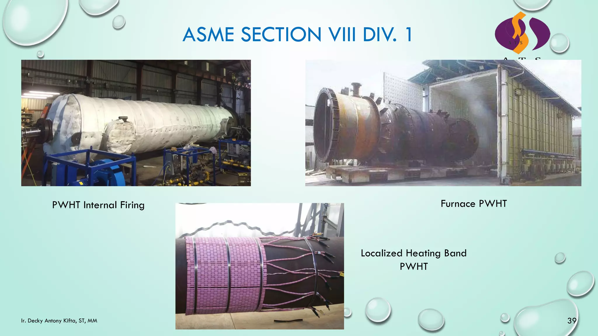
[UW-40] Procedures for PWHT
• Heating the vessel in an enclosed furnace
• Heating the vessel in more than one heat in a
furnace, provided the overlap of the heated
sections of the vessel is at least 5 feet (1.5 M).
• Partial PWHT
• Internal firing
• Localized heating
• PWHT shall be done before hydrostatic test
and after any welded repairs.
[UW-41] Sectioning of welded joints
• Welded joint may be examined by sectioning
when agreed by user and manufacturer.](https://image.slidesharecdn.com/introductiontoasmeviiidiv1ats-230705041220-f89f539f/75/Introduction-to-ASME-VIII-Div-1-ATS-pdf-33-2048.jpg)
![ASME SECTION VIII DIV. 1
34
Ir. Decky Antony Kifta, ST, MM
[UW-42] Weld Metal Buildup
• Weld metal buildup is permitted to be
performed on the construction base metal and
weld to restore the thickness of base metal for
strength consideration or to modify the
configuration of weld such as taper transition,
etc. provided that a groove welding procedure
qualification is available and covering the
thickness of weld metal deposited.
• All weld metal surfaces shall be buildup shall
be examined by MT or PT. When the buildup
incorporated into the weld joint requires RT (full
or spot), the weld metal buildup can be
included. Weld metal buildup welding shall may
use groove WPS/PQR [ASME IX – QW-202.3]
Inspection and Tests
[UW-47] Check of Welding Procedure
• The Inspector shall ensure that the Welding
Procedure employed in the construction has
been qualified to ASME IX.
[UW-48] Check of Welder and Welding Operator
Qualification
• The Manufacturer shall certify that all the
welders and welding operators employed in
construction are qualified for ASME IX.
• The Inspector shall have access to check the
welder’s or welding operator’s records.
[UW-49] Check of PWHT Practice
• The Inspector shall check and verify the PWHT
practice](https://image.slidesharecdn.com/introductiontoasmeviiidiv1ats-230705041220-f89f539f/75/Introduction-to-ASME-VIII-Div-1-ATS-pdf-34-2048.jpg)
![ASME SECTION VIII DIV. 1
35
Ir. Decky Antony Kifta, ST, MM
[UW-50] NDE on welds of Pneumatically tested
Vessels
• On welded vessels to be pneumatically tested
the MPI or PT to be tested on:
• All welds around the opening
• Fillet welds of pressure parts with throat
thickness of more than 6 mm
• Exemption may be given to vessels with
MAWP not greater than 500 psig.
[UW-51] RT of weld joints
• Examination to be performed as per ASME V,
Article 2.
• Defects revealed by RT exceeding the specified
criteria shall be repaired
• UT may be used as an alternative provided
complying with methods specified in UW-53(b)
[automated or semi-automated UT] and UW-
53(c) [PAUT]
[UW-52] Spot examination of weld joints
• One spot shall be examined on each vessel for
each 50 ft (15 m) increment of weld
• For identical vessels 50 ft (15 m) increment will
be taken across all vessels welds.
• The minimum length of the spot radiography
shall be 6 in. (150 mm)
• The acceptability of welds examined by spot
radiography shall be as per these paragraphs.
• When repair is found on the spot radiography,
two additional spots shall be radiography.
• If either of the two additional spots reveals
repair, the entire increment of weld represented
shall be rejected.
[UW-53] Ultrasonic examination of welded joints
• Ultrasonic examination of welds performed in
lieu of RT [as per UW-51(a)(4)] shall be as per
ASME VIII Div. 2 para 7.5.5 (automatic or semi-
auto UT) or by using of PAUT.](https://image.slidesharecdn.com/introductiontoasmeviiidiv1ats-230705041220-f89f539f/75/Introduction-to-ASME-VIII-Div-1-ATS-pdf-35-2048.jpg)
![ASME SECTION VIII DIV. 1
37
Ir. Decky Antony Kifta, ST, MM
Materials
[UCS-5] General
• All carbon and low alloy steel material used for
pressure vessels shall be as per ASME II and
limited to Table UCS-23 except as permitted in
UG-10 &UG-11
[UCS 6 to UCS-12] These paragraphs explain the
materials similar to UCS-5 requirements, therefore,
not discussed.
Design
[UCS-16 to UCS-33] Not discussed](https://image.slidesharecdn.com/introductiontoasmeviiidiv1ats-230705041220-f89f539f/75/Introduction-to-ASME-VIII-Div-1-ATS-pdf-37-2048.jpg)
![ASME SECTION VIII DIV. 1
38
Ir. Decky Antony Kifta, ST, MM
[UCS-56] Requirements for PWHT
• The temperature of the furnace shall not exceed
425 °C when the vessel is placed in the furnace
• Above 425 °C, the heating rate shall be not more
than 222 °C/hr divided by PV max. thickness.
During the heating, the temp variation shall be
max. 140 °C within any 4.6 m.
• Holding temp. shall be as per Table UCS-56-1
and the temp. variation during the holding temp.
shall be within 83 °C.
• Above 425 °C, the cooling rate shall be not more
than 280 °C/hr divided by PV max. thickness.
During the cooling, the temp variation shall be
max. 140 °C within any 4.6 m.
• Repair, after PWHT can be performed without
subsequent re-PWHT, provided the vessel is
made from P No. 1 Group 1, 2, and 3 materials
and total repair depth shall not exceed 1-1/2 in
thickness.](https://image.slidesharecdn.com/introductiontoasmeviiidiv1ats-230705041220-f89f539f/75/Introduction-to-ASME-VIII-Div-1-ATS-pdf-38-2048.jpg)
![ASME SECTION VIII DIV. 1
40
Ir. Decky Antony Kifta, ST, MM
Table UCS-56.1 Alternative Heat Treatment
Requirements for Carbon and Low Alloy Steels.
The holding temperature may be decreased,
however, the holding time will become longer.
[UCS-57] Radiography examination
• In addition to the requirement of UW-11, a
complete radiography examination is required
for PV with thickness: see below Table UCS-57](https://image.slidesharecdn.com/introductiontoasmeviiidiv1ats-230705041220-f89f539f/75/Introduction-to-ASME-VIII-Div-1-ATS-pdf-40-2048.jpg)
![ASME SECTION VIII DIV. 1
41
Ir. Decky Antony Kifta, ST, MM
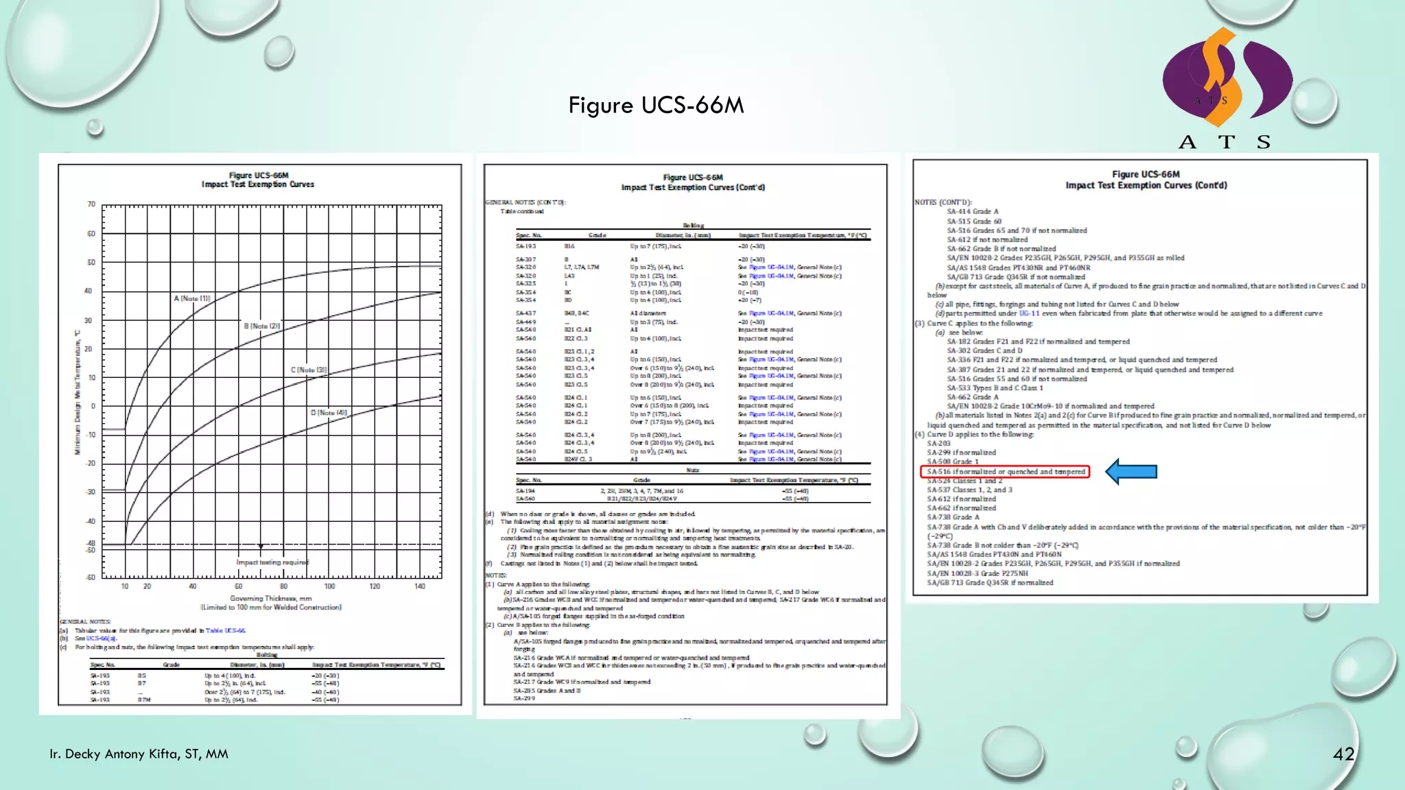
Low-Temperature Operation
[UCS-66 to UCS-68] Impact test Exemption
• Impact exemption based on UG-20(f)
• Impact exemption based on Fig. UCS-66 and
Table UCS-66.
• Reduction temp based on the coincident ratio
when the ratio < 1, a reduction to exemption may
be given as per Fig. UCS-66.1. Deduct the MDMT
from Table UCS to find the new MDMT exempted
from the impact test.
• [UCS-68(c)] allows reduction temp. by 17 °C
when the material is to be stress relieved (without
Code requirements)
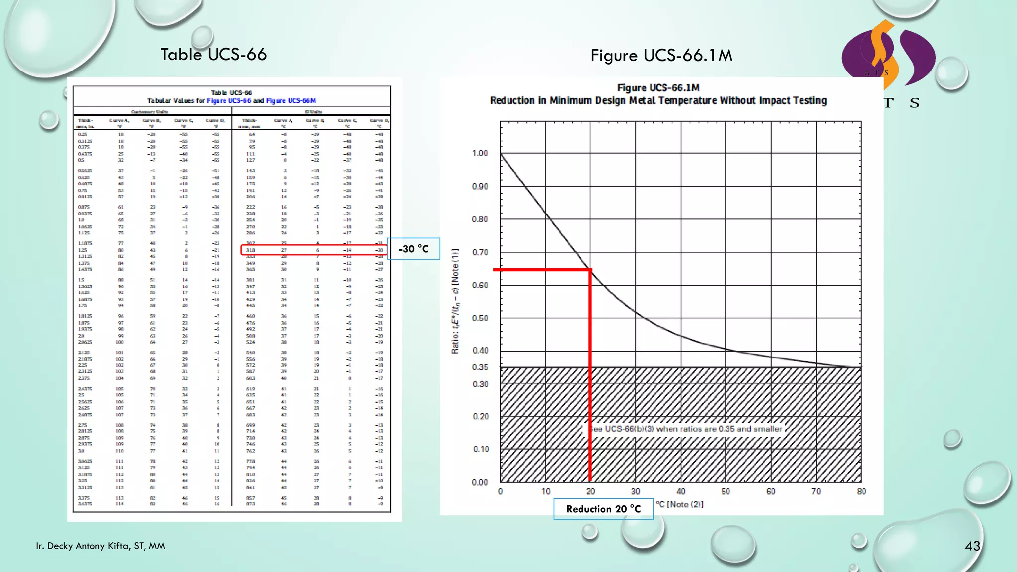
Low-Temperature Operation – for example
[UCS-66 to UCS-68] Impact test Exemption
• Material of SA 516-70 Normalized with thickness 32
mm, coincident ratio 0.64, and the vessel will be
PWHT as per Client request, what will be the MDMT?
• As per Fig.UCS-66 material SA 516-70 belongs
to Curve D
• Based on Table UCS-66 Curve D with a thickness
of 32 mm showing MDMT of -30 °C
• As per Fig. UCS-66.1 with the coincident ratio of
0.64 will give a reduction of 20 °C, this will give
new MDMT of -30 – 20 °C becomes -50 °
• The vessel will be heat treated and when
performed the final MDMT will be -50 -17 °C =
-67 °C [Refer to UCS 68(c)].](https://image.slidesharecdn.com/introductiontoasmeviiidiv1ats-230705041220-f89f539f/75/Introduction-to-ASME-VIII-Div-1-ATS-pdf-41-2048.jpg)
![ASME SECTION VIII DIV. 1
44
Ir. Decky Antony Kifta, ST, MM
Fabrication
[UCS-75 to UCS-79]
• Carbon & low alloy steel plates shall not be
formed cold by blows, however, may be formed
by blows at a forging temperature.
• P No. 1 Gr No. 1 & 2 materials heat treatment is
required when extreme fiber elongation of
forming exceeds 40% or if the extreme fiber
elongation exceeds 5% and any of the following
conditions exist:
• The vessel will contain lethal substances
• Material requires impact test
• Nominal thickness before cold forming
exceeds 16 mm.
• The thickness reduction by cold forming is
more than 10% at any location where the
extreme fiber elongation exceeds 5%.
[UCS-85]
• The material used in the vessel shall be
represented by test specimens that have been
subjected to the same heat treatments exceeding
900 °F (480 °C), except as exempted below:
• The materials belong to P No. 1 Gr. 1 & 2 and
all carbon and low alloy steels used in the
annealed condition as permitted by the material
specification are exempt from the above testing
requirement provided that heat treatments are
limited to PWHT at below lower transformation
temp. of the steel, except for SA-841.](https://image.slidesharecdn.com/introductiontoasmeviiidiv1ats-230705041220-f89f539f/75/Introduction-to-ASME-VIII-Div-1-ATS-pdf-44-2048.jpg)