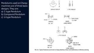
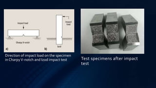
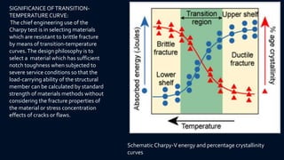
IMPACT TESTING
INTRODUCTION
• A simple tensile test does not reveal the brittle nature of the metals, and if only the tensile
test data are relied upon and the object is put into use, failure is certain.
• It is, therefore, necessary to test the material under shock or sudden loading conditions.
• The components like locomotive connecting rods, wheels etc., are subjected to impact(shock)
loads.These loads are applied suddenly.
• An impact test is used to observe the mechanics that a material will exhibit when it
experiences a shock loading that causes the specimen to immediately deform, fracture or
rupture completely.
• Notched-bar impact tests are subject to considerable scatter, particularly in the region of the
transition temperature. Most of this scatter is due to local variations in the properties of the
steel, while some is due to difficulties in preparing perfectly reproducible notches.
• Both notch shape and depth are critical variables, as is the proper placement of the specimen
in the impact machine.
Types of impact tests:
• For a single impact test the three most popular types of test are
1) the CharpyV-notch test,
2) the Izod test and
3) theTensile Impact test.
• These three tests all essentially determine the same characteristics of the
material but differ in the orientation of the test sample which causes the sample
to be stressed in different directions and involve a known weight released from
a known height colliding with the specimen in its test fixture. All of these tests
are useful in determining the impact mechanics of the test specimen.
SIGNIFICANCE OF NOTCHED-BAR IMPACT TESTING
NOTCH BEHAVIOUR:
• The notch behavior of the face-centered cubic metals and alloys, a large group of nonferrous
materials and the austenitic steels can be judged from their common tensile properties. If
they are brittle in tension, they will be brittle when notched, while if they are ductile in tension
they will be ductile when notched, except for unusually sharp or deep notches (much more
severe than the standard Charpy or Izod specimens). Even low temperatures do not alter this
characteristic of these materials.
• In contrast, the behavior of the ferritic steels under notch conditions cannot be predicted
from their properties as revealed by the tension test. For the study of these materials the
Charpy and Izod type tests are accordingly very useful. Some metals that display normal
ductility in the tension test may nevertheless break in brittle fashion when tested or when
used in the notched condition. Notched conditions include constraints to deformation in
directions perpendicular to the major stress, or multi axial stresses, and stress.
NOTCH EFFECT:
• The notch results in a combination of multi axial stresses associated with restraints to
deformation in directions perpendicular to the major stress, and a stress concentration at the
base of the notch.
• A severely notched condition is generally not desirable, and it becomes of real concern in
those cases in which it initiates a sudden and complete failure of the brittle type.
• Some metals can be deformed in a ductile manner even down to very low temperatures, while
others may crack. This difference in behavior can be best understood by considering the
cohesive strength of a material (or the property that holds it together) and its relation to the
yield point.
• In cases of brittle fracture, the cohesive strength is exceeded before significant plastic
deformation occurs and the fracture appears crystalline.
• In cases of the ductile or shear type of failure, considerable deformation precedes the final
fracture and the broken surface appears fibrous instead of crystalline.
• In intermediate cases, the fracture comes after a moderate amount of deformation and is part
crystalline and part fibrous in appearance.
CHARPY IMPACT TEST
• Charpy impact testing is a low-cost and reliable test method which is commonly required by the
construction codes for fracture-critical structures such as bridges and pressure vessels.
• It took from about 1900 to 1960 for impact-test technology and procedures to reach levels of accuracy and
reproducibility such that the procedures could be broadly applied as standard test methods.
• The Charpy impact test, also known as the Charpy V-notch test, is a high strain-rate test that involves
striking a standard notched specimen with a controlled weight pendulum swung from a set height. The
impact test helps measure the amount of energy absorbed by the specimen during fracture.
• Charpy tests show whether a metal can be classified as being either brittle or ductile. This is particularly
useful for ferritic steels that show a ductile to brittle transition with decreasing temperature. A brittle metal
will absorb a small amount of energy when impact tested, a tough ductile metal absorbs a large amount of
energy.
• The appearance of a fracture surface also gives information about the type of fracture that has occurred; a
brittle fracture is bright and crystalline, a ductile fracture is dull and fibrous. The percentage crystallinity is
determined by making a judgement of the amount of crystalline or brittle fracture on the surface of the
broken specimen, and is a measure of the amount of brittle fracture.
• Lateral expansion is a measure of the ductility of the specimen. When a ductile metal is broken, the test-
piece deforms before breaking, and material is squeezed out on the sides of the compression face. The
amount by which the specimen deforms in this way is measured and expressed as millimetres of lateral
expansion.
• The British Standard for Charpy testing is BS EN ISO 148-1:2009 and the American Standard is ASTM E23.
• The ASTM E23 Charpy testing standard uses a 2-2.5mm radius striker whereas BS ISO EN
148-1 can use either a 2mm or 8mm striker.
• Consequently, for materials with a high Charpy energy (above approx. 100J), more energy
will be absorbed by the 8mm striker than by the 2mm striker equivalent and tests carried out
using the 8mm striker will report higher impact energy.
• To carry out the test the standard specimen is supported at its two ends on an anvil and
struck on the opposite face to the notch by a pendulum .The specimen is fractured and the
pendulum swings through, the height of the swing being a measure of the amount of energy
absorbed in fracturing the specimen. Conventionally three specimens are tested at any one
temperature, and the results averaged.
• When reporting the results of a Charpy test, the absorbed energy (in Joules) is always
reported, while the percentage crystallinity and lateral expansion are optional on the test
report.
• It should be emphasised that Charpy tests are qualitative, the results can only be compared
with each other or with a requirement in a specification - they cannot be used to calculate the
fracture toughness of a metal.
TEST SPECIMEN OF CHARPY IMPACT TEST:
• The standard Charpy-V notch
specimen is 55mm long, 10mm square
and has a 2mm deep notch with a tip
radius of 0.25mm machined on one
face.
• The notch shall be carefully prepared so
that the root radius of the notch is free
of machining marks which could affect
the absorbed energy.
• The plane of symmetry of the notch
shall be perpendicular to the
longitudinal axis of the test piece.
• The specimens shown in Fig.1 are those
most widely used and most generally
satisfactory.They are particularly
suitable for ferrous metals, excepting
cast iron.
Pendulums used on Charpy
machines are of three basic
designs.They are:
a) C-type Pendulum
b) Compound Pendulum
c) U-type Pendulum
• A weighted pendulum, which is held
at some height h from the sample,
swings and impacts the sample at a
very high strain rate. The pendulum
then continues to swing until
reaching a final height of h′. The
difference between the potential
energies at height h and h′ is
considering to be the energy that
the sample absorbed upon impact.
Energy absorbed=mg(h-h’)
where;
m=mass of stricker hammer,
g=acceleration due to gravity
=9.8m/s2
Charpy testing machine
Test specimens after impact
test
Direction of impact load on the specimen
in CharpyV-notch and Izod impact test
1)The absorbed energy shall be taken as the difference between the energy in the striking member at the instant of
impact with the specimen and the energy remaining after breaking the specimen.This value is determined by the
machine’s scale reading which has been corrected for windage and friction losses.
2)Lateral expansion:
A measure of the ability of the material to resist fracture when subjected to triaxial stresses, such as those at the
root of the notch in a Charpy test piece, is the amount of deformation that occurs at this location.The deformation
in this case is contraction. Because of the difficulties in measuring this deformation, even after fracture, the
expansion that occurs at the opposite end of the fracture plane is customarily measured and used as a proxy for the
contraction.
3)Fracture appearance:
The fracture surface of Charpy test pieces is often rated by the percentage of shear fracture which occurs. The
greater the percentage of shear fracture, the greater the notch toughness of the material. The fracture surface of
most Charpy specimens exhibits a mixture of shear and flat fracture regions. The shear regions are assumed to be
fully ductile, but the flat fracture regions can be ductile, brittle, or a combination of these fracture modes. Because
the rating is extremely subjective, it is recommended that it is not to be used in specifications.
NOTE: The term fibrous-fracture appearance is often used as a synonym for shear fracture appearance. The terms
cleavage fracture appearance and crystallinity are often used to express the opposite of shear fracture.
Information Obtainable from Impact Tests
Schematic Charpy-V energy and percentage crystallinity
curves
SIGNIFICANCEOFTRANSITION-
TEMPERATURECURVE:
The chief engineering use of the
Charpy test is in selecting materials
which are resistant to brittle fracture
by means of transition-temperature
curves.The design philosophy is to
select a material which has sufficient
notch toughness when subjected to
severe service conditions so that the
load-carrying ability of the structural
member can be calculated by standard
strength of materials methods without
considering the fracture properties of
the material or stress concentration
effects of cracks or flaws.
ADVANTAGES OF IMPACT TESTING
• The principal advantages of the Charpy V-notch impact test is that it is a relatively
simple test that utilizes a relatively cheap, small test specimen.
• Tests can readily be carried out over a range of subambient temperatures.
• Moreover, the design of the test specimen is well suited for measuring differences in
notch toughness in low-strength materials such as structural steels.
• The test is used for comparing the influence of alloy studies and heat treatment on
notch toughness.
• It is frequently used for quality control and material acceptance purposes.
LIMITATIONS OF IMPACT TESTING
• These test methods do not address the problems associated with impact testing at
temperatures below –196 °C (–320 °F, 77 K).
• The results of the tests obtained are difficult to use in design.
• Since there is no measurement in terms of stress level, it is difficult to correlate CV (the
energy required for fracture of a Charpy specimen) data with service performance.
• Moreover, there is no correlation of Charpy data with flaw size.
• In addition, the large scatter inherent in the test may make it difficult to determine
well-defined transition-temperature curves.
• The chief deficiency of the Charpy impact test is that the small specimen is not always a
realistic model of the actual situation. Not only does the small specimen lead to
considerable scatter, but a specimen with a thickness of 10 mm cannot provide the
same constraint as would be found in a structure with a much greater thickness.
IZOD IMPACT TEST
• The Izod test has become the standard testing procedure for comparing the impact
resistances of plastics. While being the standard for plastics, it is also used on other materials.
• The Izod test is most commonly used to evaluate the relative toughness or impact toughness
of materials and as such is often used in quality control applications where it is a fast and
economical test. It is used more as a comparative test rather than a definitive test. This is also
in part due to the fact that the values do not relate accurately to the impact strength of
moulded parts or actual components under actual operational conditions.
• The Izod test involves striking a suitable test piece with a striker, mounted at the end of a
pendulum. The test piece is clamped vertically with the notch facing the striker. The striker
swings downwards impacting the test piece at the bottom of its swing.
Schematic diagram of Izod impact test
• The standard test piece of overall
length of 75mm and a square cross-
section of 10mm side with a standard
45° notch, 2mm deep is employed for
the test.The notch is at 28mm from
one end.
• The notch shall be carefully prepared
so that the root radius of the notch is
free of machining marks which could
affect the absorbed energy.
• The plane of symmetry of the notch
shall be perpendicular to the
longitudinal axis of the test piece.
• The specimen shown in Fig.2 is the
most widely used and most generally
satisfactory. It is particularly suitable
for ferrous metals, excepting cast iron.
TEST SPECIMEN OF IZOD IMPACT TEST:
THANK YOU

Impact testing

  • 1.
  • 2.
    INTRODUCTION • A simpletensile test does not reveal the brittle nature of the metals, and if only the tensile test data are relied upon and the object is put into use, failure is certain. • It is, therefore, necessary to test the material under shock or sudden loading conditions. • The components like locomotive connecting rods, wheels etc., are subjected to impact(shock) loads.These loads are applied suddenly. • An impact test is used to observe the mechanics that a material will exhibit when it experiences a shock loading that causes the specimen to immediately deform, fracture or rupture completely. • Notched-bar impact tests are subject to considerable scatter, particularly in the region of the transition temperature. Most of this scatter is due to local variations in the properties of the steel, while some is due to difficulties in preparing perfectly reproducible notches. • Both notch shape and depth are critical variables, as is the proper placement of the specimen in the impact machine.
  • 3.
    Types of impacttests: • For a single impact test the three most popular types of test are 1) the CharpyV-notch test, 2) the Izod test and 3) theTensile Impact test. • These three tests all essentially determine the same characteristics of the material but differ in the orientation of the test sample which causes the sample to be stressed in different directions and involve a known weight released from a known height colliding with the specimen in its test fixture. All of these tests are useful in determining the impact mechanics of the test specimen.
  • 4.
    SIGNIFICANCE OF NOTCHED-BARIMPACT TESTING NOTCH BEHAVIOUR: • The notch behavior of the face-centered cubic metals and alloys, a large group of nonferrous materials and the austenitic steels can be judged from their common tensile properties. If they are brittle in tension, they will be brittle when notched, while if they are ductile in tension they will be ductile when notched, except for unusually sharp or deep notches (much more severe than the standard Charpy or Izod specimens). Even low temperatures do not alter this characteristic of these materials. • In contrast, the behavior of the ferritic steels under notch conditions cannot be predicted from their properties as revealed by the tension test. For the study of these materials the Charpy and Izod type tests are accordingly very useful. Some metals that display normal ductility in the tension test may nevertheless break in brittle fashion when tested or when used in the notched condition. Notched conditions include constraints to deformation in directions perpendicular to the major stress, or multi axial stresses, and stress.
  • 5.
    NOTCH EFFECT: • Thenotch results in a combination of multi axial stresses associated with restraints to deformation in directions perpendicular to the major stress, and a stress concentration at the base of the notch. • A severely notched condition is generally not desirable, and it becomes of real concern in those cases in which it initiates a sudden and complete failure of the brittle type. • Some metals can be deformed in a ductile manner even down to very low temperatures, while others may crack. This difference in behavior can be best understood by considering the cohesive strength of a material (or the property that holds it together) and its relation to the yield point. • In cases of brittle fracture, the cohesive strength is exceeded before significant plastic deformation occurs and the fracture appears crystalline. • In cases of the ductile or shear type of failure, considerable deformation precedes the final fracture and the broken surface appears fibrous instead of crystalline. • In intermediate cases, the fracture comes after a moderate amount of deformation and is part crystalline and part fibrous in appearance.
  • 6.
    CHARPY IMPACT TEST •Charpy impact testing is a low-cost and reliable test method which is commonly required by the construction codes for fracture-critical structures such as bridges and pressure vessels. • It took from about 1900 to 1960 for impact-test technology and procedures to reach levels of accuracy and reproducibility such that the procedures could be broadly applied as standard test methods. • The Charpy impact test, also known as the Charpy V-notch test, is a high strain-rate test that involves striking a standard notched specimen with a controlled weight pendulum swung from a set height. The impact test helps measure the amount of energy absorbed by the specimen during fracture. • Charpy tests show whether a metal can be classified as being either brittle or ductile. This is particularly useful for ferritic steels that show a ductile to brittle transition with decreasing temperature. A brittle metal will absorb a small amount of energy when impact tested, a tough ductile metal absorbs a large amount of energy. • The appearance of a fracture surface also gives information about the type of fracture that has occurred; a brittle fracture is bright and crystalline, a ductile fracture is dull and fibrous. The percentage crystallinity is determined by making a judgement of the amount of crystalline or brittle fracture on the surface of the broken specimen, and is a measure of the amount of brittle fracture. • Lateral expansion is a measure of the ductility of the specimen. When a ductile metal is broken, the test- piece deforms before breaking, and material is squeezed out on the sides of the compression face. The amount by which the specimen deforms in this way is measured and expressed as millimetres of lateral expansion. • The British Standard for Charpy testing is BS EN ISO 148-1:2009 and the American Standard is ASTM E23.
  • 7.
    • The ASTME23 Charpy testing standard uses a 2-2.5mm radius striker whereas BS ISO EN 148-1 can use either a 2mm or 8mm striker. • Consequently, for materials with a high Charpy energy (above approx. 100J), more energy will be absorbed by the 8mm striker than by the 2mm striker equivalent and tests carried out using the 8mm striker will report higher impact energy. • To carry out the test the standard specimen is supported at its two ends on an anvil and struck on the opposite face to the notch by a pendulum .The specimen is fractured and the pendulum swings through, the height of the swing being a measure of the amount of energy absorbed in fracturing the specimen. Conventionally three specimens are tested at any one temperature, and the results averaged. • When reporting the results of a Charpy test, the absorbed energy (in Joules) is always reported, while the percentage crystallinity and lateral expansion are optional on the test report. • It should be emphasised that Charpy tests are qualitative, the results can only be compared with each other or with a requirement in a specification - they cannot be used to calculate the fracture toughness of a metal.
  • 8.
    TEST SPECIMEN OFCHARPY IMPACT TEST: • The standard Charpy-V notch specimen is 55mm long, 10mm square and has a 2mm deep notch with a tip radius of 0.25mm machined on one face. • The notch shall be carefully prepared so that the root radius of the notch is free of machining marks which could affect the absorbed energy. • The plane of symmetry of the notch shall be perpendicular to the longitudinal axis of the test piece. • The specimens shown in Fig.1 are those most widely used and most generally satisfactory.They are particularly suitable for ferrous metals, excepting cast iron.
  • 9.
    Pendulums used onCharpy machines are of three basic designs.They are: a) C-type Pendulum b) Compound Pendulum c) U-type Pendulum
  • 10.
    • A weightedpendulum, which is held at some height h from the sample, swings and impacts the sample at a very high strain rate. The pendulum then continues to swing until reaching a final height of h′. The difference between the potential energies at height h and h′ is considering to be the energy that the sample absorbed upon impact. Energy absorbed=mg(h-h’) where; m=mass of stricker hammer, g=acceleration due to gravity =9.8m/s2 Charpy testing machine
  • 11.
    Test specimens afterimpact test Direction of impact load on the specimen in CharpyV-notch and Izod impact test
  • 12.
    1)The absorbed energyshall be taken as the difference between the energy in the striking member at the instant of impact with the specimen and the energy remaining after breaking the specimen.This value is determined by the machine’s scale reading which has been corrected for windage and friction losses. 2)Lateral expansion: A measure of the ability of the material to resist fracture when subjected to triaxial stresses, such as those at the root of the notch in a Charpy test piece, is the amount of deformation that occurs at this location.The deformation in this case is contraction. Because of the difficulties in measuring this deformation, even after fracture, the expansion that occurs at the opposite end of the fracture plane is customarily measured and used as a proxy for the contraction. 3)Fracture appearance: The fracture surface of Charpy test pieces is often rated by the percentage of shear fracture which occurs. The greater the percentage of shear fracture, the greater the notch toughness of the material. The fracture surface of most Charpy specimens exhibits a mixture of shear and flat fracture regions. The shear regions are assumed to be fully ductile, but the flat fracture regions can be ductile, brittle, or a combination of these fracture modes. Because the rating is extremely subjective, it is recommended that it is not to be used in specifications. NOTE: The term fibrous-fracture appearance is often used as a synonym for shear fracture appearance. The terms cleavage fracture appearance and crystallinity are often used to express the opposite of shear fracture. Information Obtainable from Impact Tests
  • 14.
    Schematic Charpy-V energyand percentage crystallinity curves SIGNIFICANCEOFTRANSITION- TEMPERATURECURVE: The chief engineering use of the Charpy test is in selecting materials which are resistant to brittle fracture by means of transition-temperature curves.The design philosophy is to select a material which has sufficient notch toughness when subjected to severe service conditions so that the load-carrying ability of the structural member can be calculated by standard strength of materials methods without considering the fracture properties of the material or stress concentration effects of cracks or flaws.
  • 15.
    ADVANTAGES OF IMPACTTESTING • The principal advantages of the Charpy V-notch impact test is that it is a relatively simple test that utilizes a relatively cheap, small test specimen. • Tests can readily be carried out over a range of subambient temperatures. • Moreover, the design of the test specimen is well suited for measuring differences in notch toughness in low-strength materials such as structural steels. • The test is used for comparing the influence of alloy studies and heat treatment on notch toughness. • It is frequently used for quality control and material acceptance purposes.
  • 16.
    LIMITATIONS OF IMPACTTESTING • These test methods do not address the problems associated with impact testing at temperatures below –196 °C (–320 °F, 77 K). • The results of the tests obtained are difficult to use in design. • Since there is no measurement in terms of stress level, it is difficult to correlate CV (the energy required for fracture of a Charpy specimen) data with service performance. • Moreover, there is no correlation of Charpy data with flaw size. • In addition, the large scatter inherent in the test may make it difficult to determine well-defined transition-temperature curves. • The chief deficiency of the Charpy impact test is that the small specimen is not always a realistic model of the actual situation. Not only does the small specimen lead to considerable scatter, but a specimen with a thickness of 10 mm cannot provide the same constraint as would be found in a structure with a much greater thickness.
  • 17.
    IZOD IMPACT TEST •The Izod test has become the standard testing procedure for comparing the impact resistances of plastics. While being the standard for plastics, it is also used on other materials. • The Izod test is most commonly used to evaluate the relative toughness or impact toughness of materials and as such is often used in quality control applications where it is a fast and economical test. It is used more as a comparative test rather than a definitive test. This is also in part due to the fact that the values do not relate accurately to the impact strength of moulded parts or actual components under actual operational conditions. • The Izod test involves striking a suitable test piece with a striker, mounted at the end of a pendulum. The test piece is clamped vertically with the notch facing the striker. The striker swings downwards impacting the test piece at the bottom of its swing.
  • 18.
    Schematic diagram ofIzod impact test
  • 19.
    • The standardtest piece of overall length of 75mm and a square cross- section of 10mm side with a standard 45° notch, 2mm deep is employed for the test.The notch is at 28mm from one end. • The notch shall be carefully prepared so that the root radius of the notch is free of machining marks which could affect the absorbed energy. • The plane of symmetry of the notch shall be perpendicular to the longitudinal axis of the test piece. • The specimen shown in Fig.2 is the most widely used and most generally satisfactory. It is particularly suitable for ferrous metals, excepting cast iron. TEST SPECIMEN OF IZOD IMPACT TEST:
  • 20.