Downloaded 183 times


![5
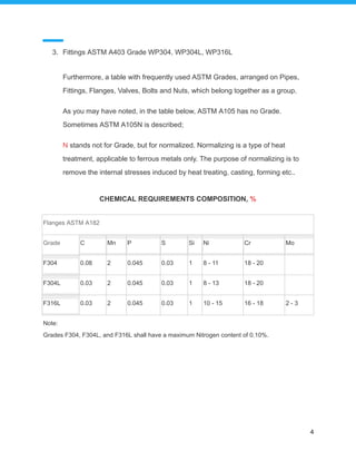
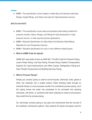
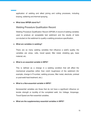
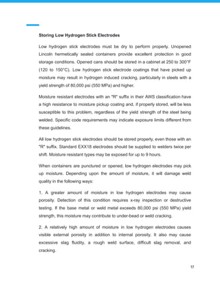
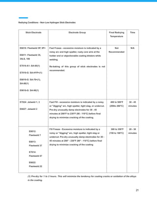
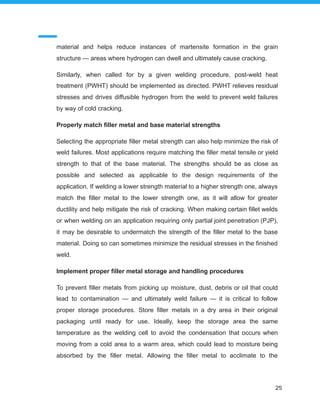
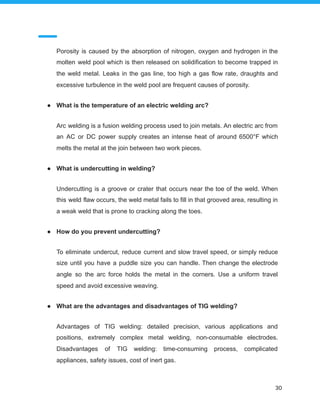
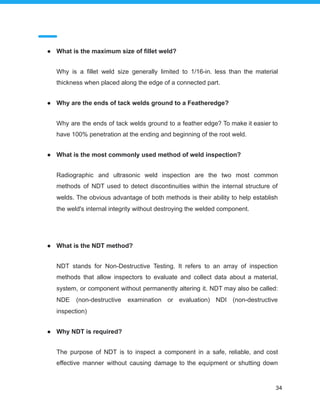
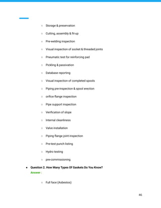
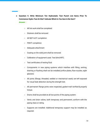
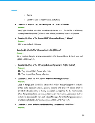
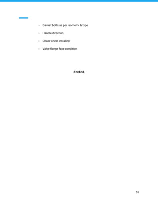
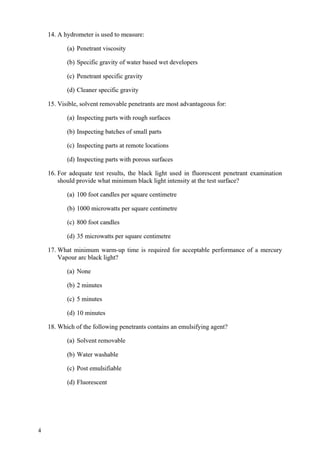
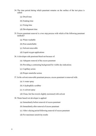
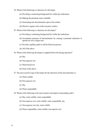
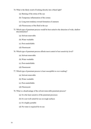
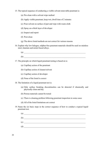
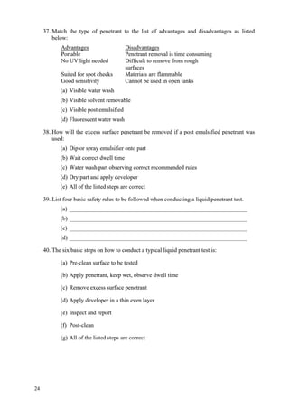
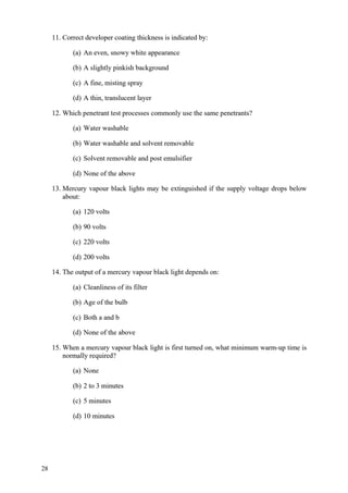
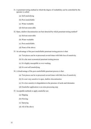
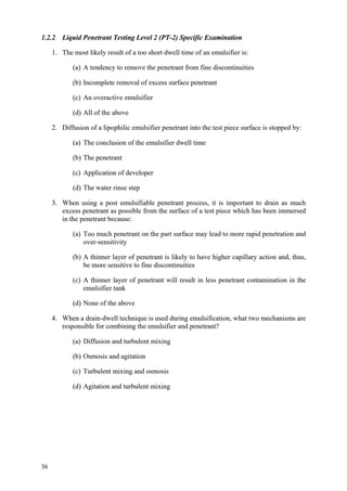
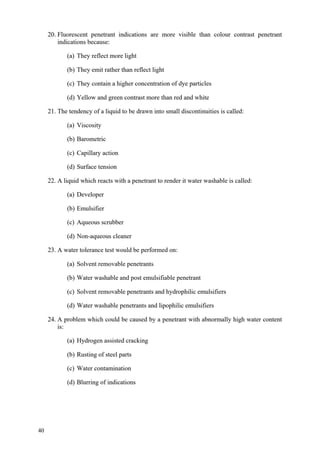
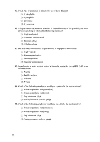
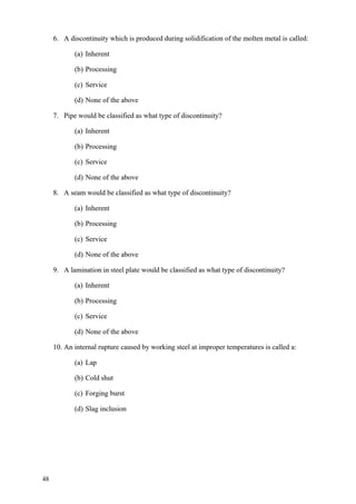
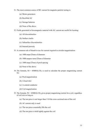
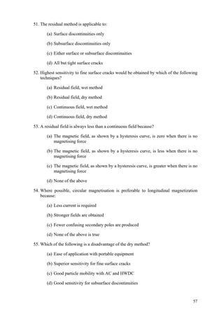
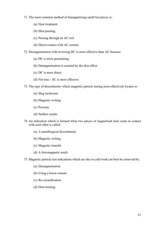
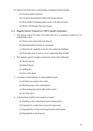
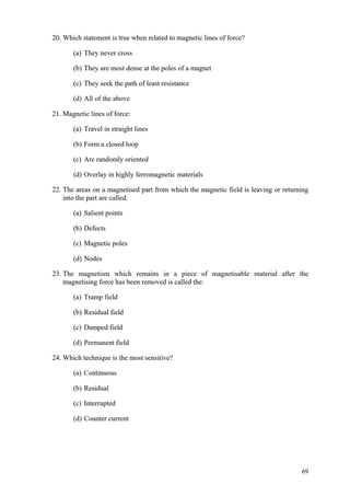
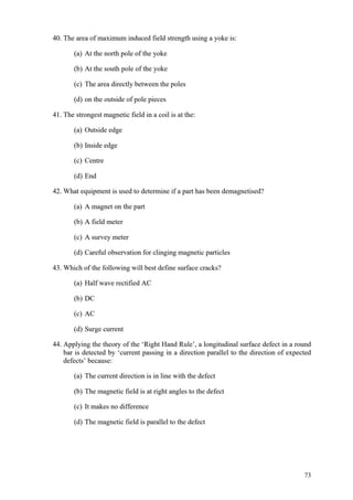
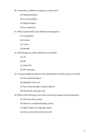
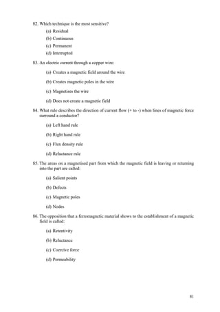
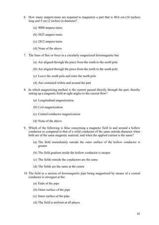
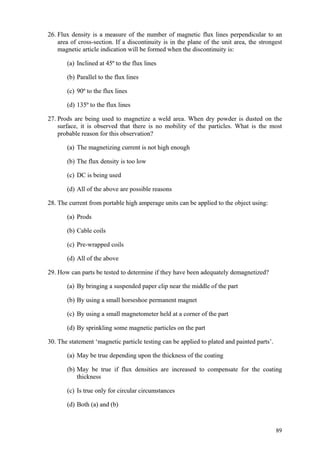
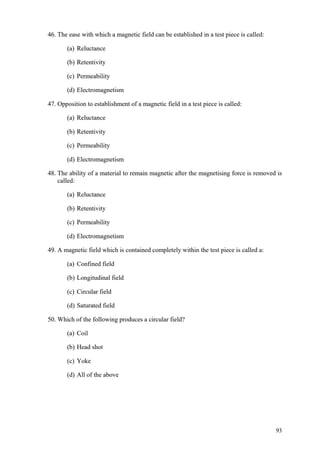
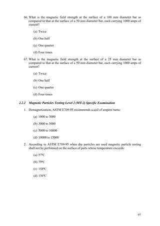
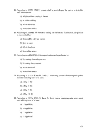
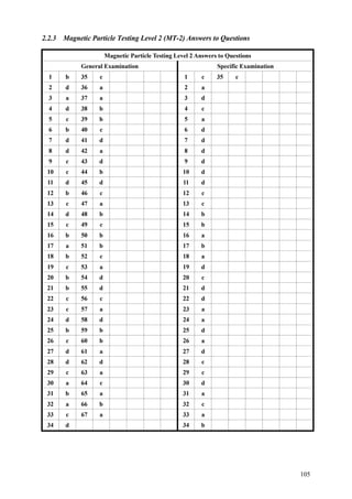
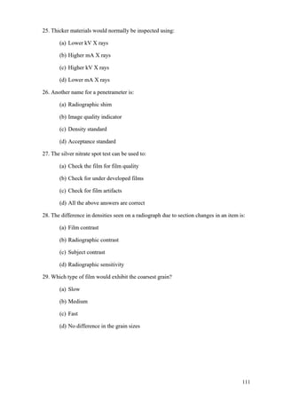
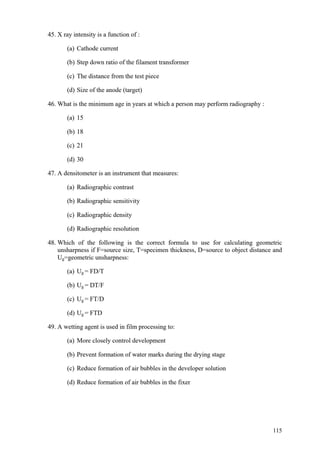
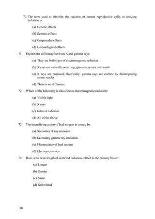
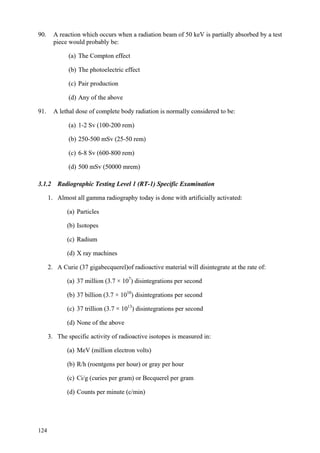
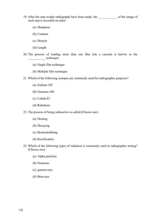
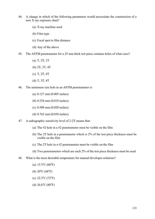
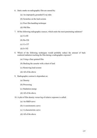
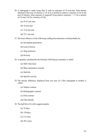
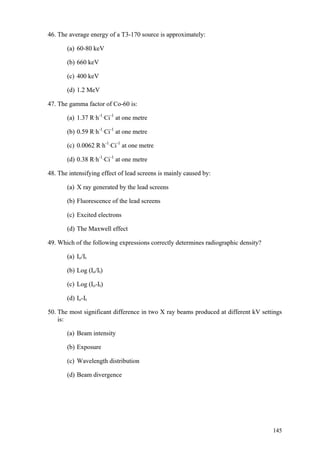
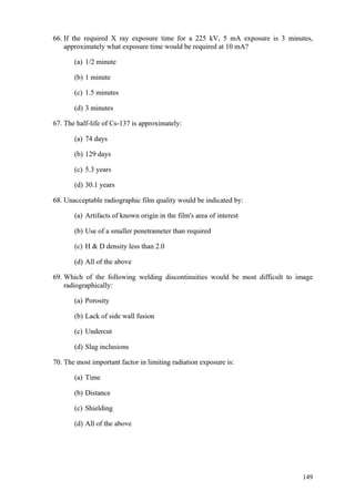
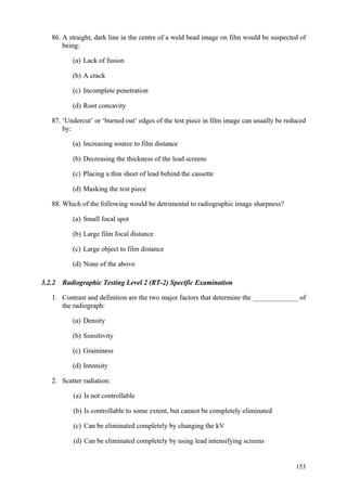
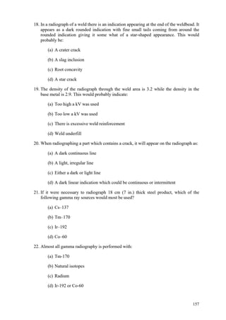
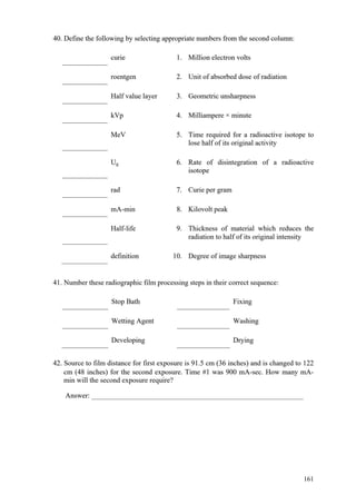
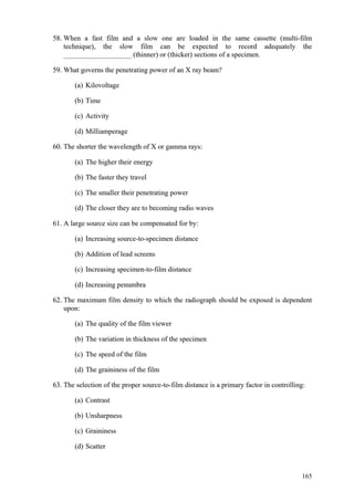
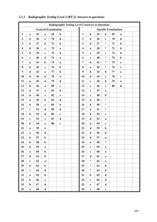
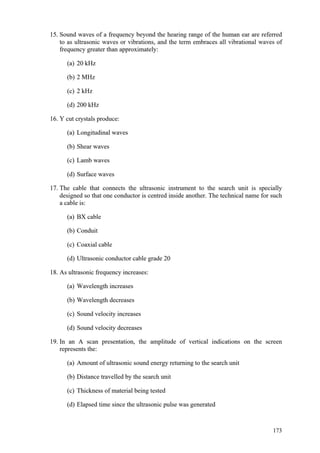
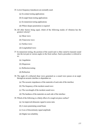
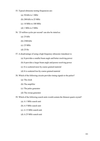
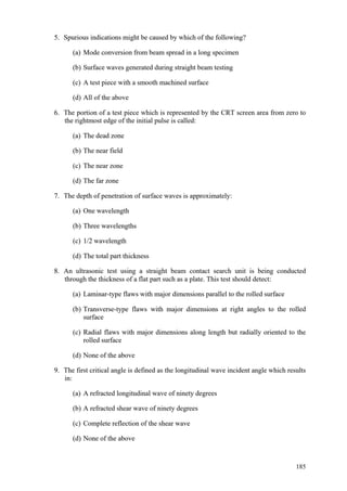
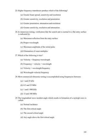
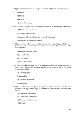
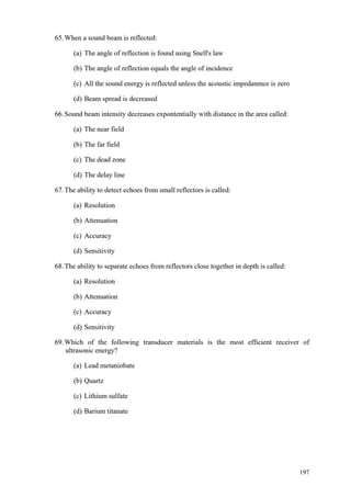
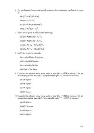
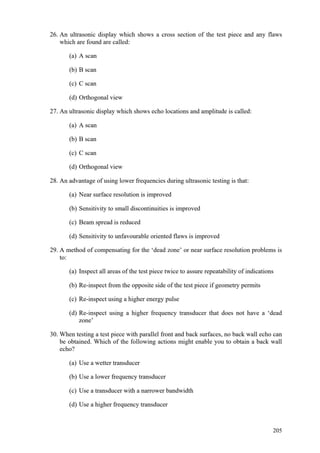
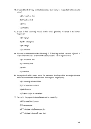
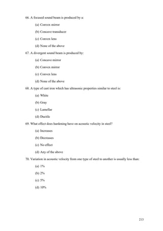
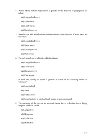
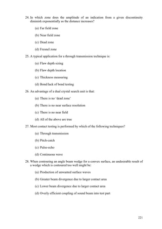
Pipes ASTM A312
Grade C Mn P S Si Cr Ni Mo
TP 304 0.08 2 0.045 0.03 1 18 - 20 8 - 11
TP 304L 0.035 2 0.045 0.03 1 18 - 20 8 - 13
TP 316L 0.035 2 0.045 0.03 1 16 - 18 10 - 14 2 - 3
Note:
For small diameter or thin walls or both, where many drawing passes are required, a Carbon
maximum of 0.040% is necessary in grades TP304L and TP316L. Small outside diameter tubes are
defined as those less than 0.50 in. [12.7 mm] in outside diameter and light wall tubes as those less
than 0.049 in. [1.20 mm] in average wall thickness (0.044 in. [1.10 mm] in minimum wall thickness).
Fittings ASTM A403
Grade C
(1)
Mn
(1)
P
(1)
S
(1)
Si
(1)
Ni Cr Mo
WP 304 0.08 2 0.045 0.03 1 8 - 11 18 - 20
WP 304L 0.03 (2) 2 0.045 0.03 1 8 - 12 18 - 20
WP 316L 0.03 (2) 2 0.045 0.03 1 10 - 14 (3) 16 - 18 2 - 3
Notes:
(1) Maximum, unless otherwise indicated.
(2) For small diameter or thin walls or both, where many drawing passes are required, a Carbon
maximum of 0.040% is necessary in grades TP304L and TP316L. Small outside diameter tubes are
defined as those less than 0.50 in. [12.7 mm] in outside diameter and light wall tubes as those less
than 0.049 in. [1.20 mm] in average wall thickness (0.044 in. [1.10 mm] in minimum wall thickness).](https://image.slidesharecdn.com/qcweldinginspectorinterviewquestionanswers-221217155906-c2427cec/85/QC-Welding-Inspector-Interview-Question-Answers-pdf-6-320.jpg)
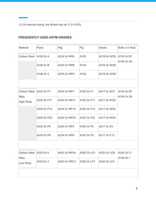
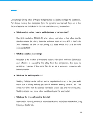
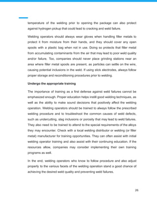
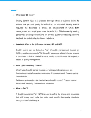
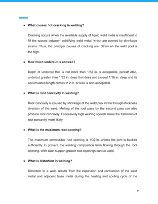
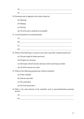
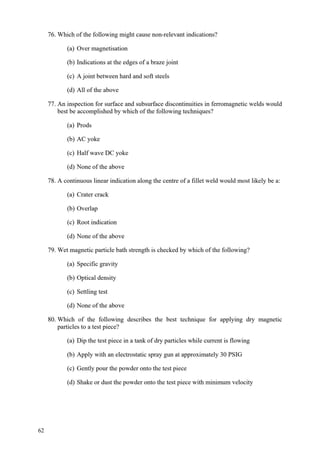
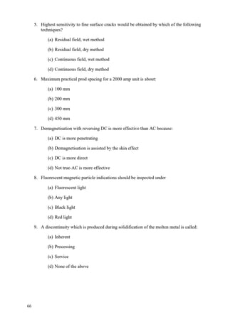
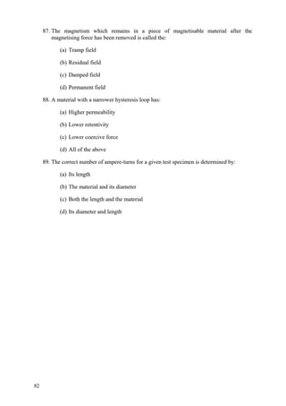
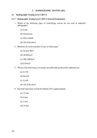
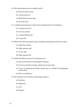
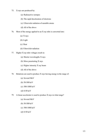
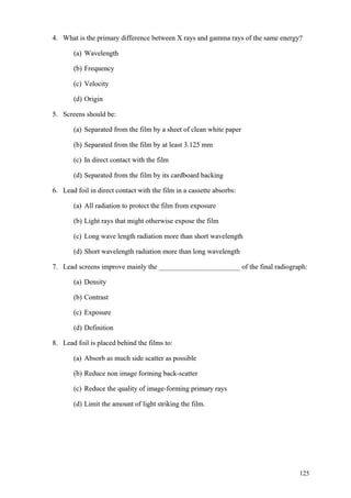
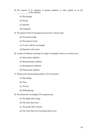
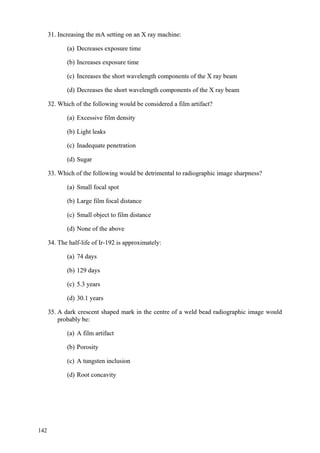
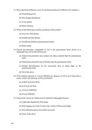
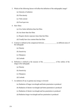
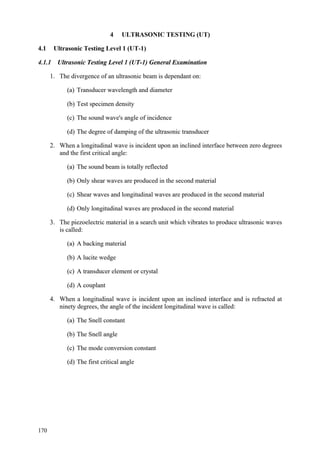
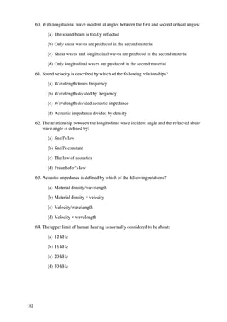
![select welding parameters (high current level, short arc length, not too high a
welding speed) to promote penetration into the joint side wall without causing
flooding
ensure the electrode/gun angle and manipulation technique will give adequate
side wall fusion
use weaving and dwell to improve side wall fusion providing there are no heat
input restrictions
if arc blow occurs, reposition the current return, use AC (in MMA [SMA]
welding) or demagnetise the steel
● What are inclusions in welding?
Slag inclusions are nonmetallic particles trapped in the weld metal or at the
weld interface. Slag inclusions result from faulty welding technique, improper
access to the joint, or both. Tungsten inclusions are tungsten particles trapped
in weld metal deposited with the gas tungsten arc welding process
● What is incomplete fusion in welding?
Incomplete fusion is a weld discontinuity in which fusion did not occur between
weld metal and fusion faces or adjoining weld beads. This absence of fusion
may occur at any location within the weld joint and may be present in fillet
welds and/or groove welds.
● What causes tungsten inclusion?
A tungsten inclusion is most often caused by dipping the tungsten electrode into
the weld pool or touching the filler metal rod to the tungsten while welding. It
28](https://image.slidesharecdn.com/qcweldinginspectorinterviewquestionanswers-221217155906-c2427cec/85/QC-Welding-Inspector-Interview-Question-Answers-pdf-29-320.jpg)
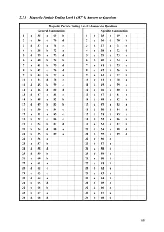
![specified amount of time. It is often referred to as being any heat treatment
performed after welding; however, within the oil, gas, petrochemical and nuclear
industries, it has a specific meaning. Industry codes, such as the ASME
Pressure Vessel and Piping Codes, often require mandatory performance of
PWHT on certain materials to ensure a safe design with optimal mechanical
and metallurgical properties.
The need for PWHT is mostly due to the residual stresses and micro-structural
changes that occur after welding has been completed.[2] During the welding
process, a high temperature gradient is experienced between the weld metal
and the parent material. As the weld cools, residual stress is formed.[2] For
thicker materials, these stresses can reach an unacceptable level and exceed
design stresses. Therefore, the part is heated to a specified temperature for a
given amount of time to reduce these stresses to an acceptable level.[1] In
addition to residual stresses, microstructural changes occur due to the high
temperatures induced by the welding process.[1] These changes can increase
hardness of the material and reduce toughness and ductility. The use of PWHT
can help reduce any increased hardness levels and improve toughness and
ductility to levels acceptable for design.[1]
The requirements specified within various pressure vessels and piping codes
are mostly due to the chemical makeup and thickness of the material.[1] Codes
such as ASME Section VIII and ASME B31.3 will require that a specified
material be post weld heat treated if it is over a given thickness.[1] Codes also
require PWHT based solely on the micro-structural make-up of the material.[1]
A final consideration in deciding the need for PWHT is based on the
components' intended service, such as one with a susceptibility to stress
corrosion cracking. In such cases, PWHT is mandatory regardless of
thickness.[4]
37](https://image.slidesharecdn.com/qcweldinginspectorinterviewquestionanswers-221217155906-c2427cec/85/QC-Welding-Inspector-Interview-Question-Answers-pdf-38-320.jpg)
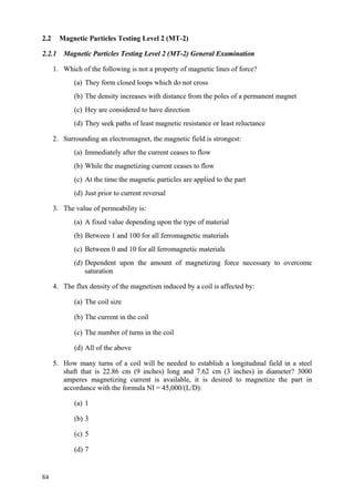
![Rate of heating, hold times and temperatures, and rate of cooling are all
important variables that need to be controlled and monitored precisely, or the
desired effects may not be achieved.[3] When PWHT is mandatory by a given
industry code, requirements for these variables will be specified.[3][4][5]
Heating
The rate of heating when PWHT is performed is typically based on the
component’s thickness and is specified by the governing codes.[1][6] If the rate
of heating is not performed properly, either by heating too quickly or unevenly,
temperature gradients within the component can become detrimental to the
component. As a result, stress cracks may occur and residual stresses not
previously created can form when the component is cooled to ambient
temperatures.[4]
Holding temperature and time
Holding temperature and time are governed by the material and thickness
respectively.[4][6] Regarding material thickness, longer holding times are
needed for thicker materials.[4] This is to allow the material to reach a stable
condition where the distribution and levels of stresses become more uniform
and decrease.[2][6] The specified holding temperature is one that is at a high
enough temperature to relieve high residual stress levels, yet is still below the
lower transformation temperature.[1][2] In addition to the reduction of stress,
high hold temperatures below the transformation temperature allow for
microstructural transformations, therein reducing hardness and improving
ductility.[6] Great care should be taken as to not heat the component above the
lower transformation temperature, as detrimental metallurgical effects and
impaired mechanical properties can result.[6] In addition, the holding
temperature should not be greater than the original tempering temperature
unless later mechanical testing is performed. Holding above the original
38](https://image.slidesharecdn.com/qcweldinginspectorinterviewquestionanswers-221217155906-c2427cec/85/QC-Welding-Inspector-Interview-Question-Answers-pdf-39-320.jpg)
![tempering temperature can reduce the strength of the material to below ASME
required minimums.[4]
Cooling
As with the heating rate, the cooling rate must be controlled, as to avoid any
detrimental temperature gradients that could cause cracking or introduce new
stresses during cooling.[4] In addition to this, rapid cooling rates can increase
hardness, which may increase the susceptibility of a brittle fracture.[7]
Monitoring technique
Thermocouples are typically attached to the component undergoing PWHT to
check and ensure that heating rates, hold temperatures, and cooling rates meet
code specification. Computer software is typically used in conjunction with the
thermocouples to monitor the fore-mentioned variables and provide
documentation that the PWHT was performed properly.[5]
Why do we preheat before welding?
Preheating is the process applied to raise the temperature of the parent steel
before welding. It is used for the following main reasons:
The slower cooling rate encourages hydrogen diffusion from the weld area by
extending the time period over which it is at elevated temperature (particularly
the time at temperatures above approximately 100°C) at which temperatures
hydrogen diffusion rates are significantly higher than at ambient temperature.
The reduction in hydrogen reduces the risk of cracking.
To slow the cooling rate of the weld and the base material, potentially resulting
in softer weld metal and heat affected zone microstructures with a greater
resistance to fabrication hydrogen cracking.
39](https://image.slidesharecdn.com/qcweldinginspectorinterviewquestionanswers-221217155906-c2427cec/85/QC-Welding-Inspector-Interview-Question-Answers-pdf-40-320.jpg)
![Preheat can be applied through various means. The choice of method of
applying preheat will depend on the material thickness, weldment size and the
heating equipment available at the time of welding. The methods can include
furnace heating for small production assemblies or, for large structural
components, arrays of torches, electrical strip heaters, induction heaters or
radiation heaters.
It is important to apply preheat correctly, with appropriate monitors and controls,
and also to monitor the interpass temperature (the temperature of the
workpiece between welding the first and subsequent passes), to ensure that it
does not fall below the preheat temperature. (See FAQ: Which is important -
Preheat or interpass?).
Common techniques for monitoring preheat are temperature indicating crayons
(see FAQ: What is a Tempil stick?) and thermocouples or contact
thermometers. Preheat should be monitored at a distance of 4t (where t is the
thickness of the material to be joined) away from the longitudinal edge of the
groove for t<50mm [1] or at a minimum distance of 75mm from the joint
preparation for t>50mm and on the reverse side of the plate to the heat source
[1,2].
How many thermocouples are required during PWHT?
For pipes up to and including 10 inches, one thermocouple attached to the 6
o'clock position in horizontal pipes is sufficient. For pipes 12 inches and larger,
two thermocouples, one on the 6 o'clock and the other one on the 12 o'clock
positions are necessary. Never attach them on the 3 o'clock nor on the 9 o'clock
positions. In vertical pipes, of course, you can attach them in any position.
40](https://image.slidesharecdn.com/qcweldinginspectorinterviewquestionanswers-221217155906-c2427cec/85/QC-Welding-Inspector-Interview-Question-Answers-pdf-41-320.jpg)
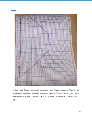


This document provides concise summaries of key terms and concepts for a QC welding inspector interview. It defines common quality control terms like QA, QC, QAP, ITP, and explains the differences between them. It also summarizes welding concepts such as the four main welding types, the purpose of welding procedures like WPS and PQR, essential versus non-essential variables, and what organizations like ASME and AWS stand for.