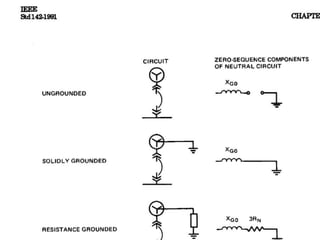
1. Medium voltage systems can use different neutral grounding methods including solid grounding, impedance grounding, and high resistance grounding.
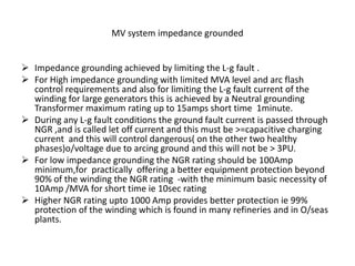
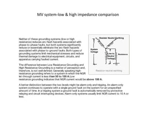
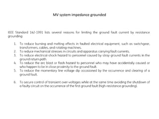
2. Impedance grounding limits line-to-ground fault current using a neutral grounding resistor or transformer, while high resistance grounding is used to control arc flash hazards in mines.
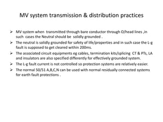
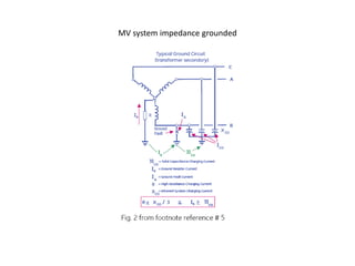
3. The neutral grounding method affects protection schemes, equipment ratings, and overvoltage stresses on the system. Core balancing CTs and open delta PTs are commonly used for earth fault detection on impedance grounded systems.