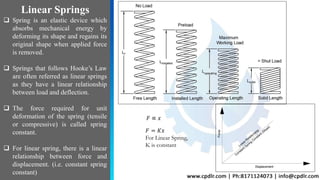
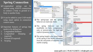
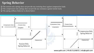
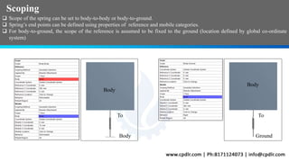
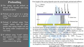
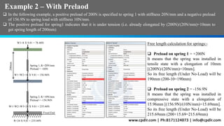
SlideShare a Scribd company logo
SIMULATING LINEAR SPRING
BEHAVIOR USING SPRING
CONNECTION IN ANSYS FEA
Linear Springs
 Spring is an elastic device which
absorbs mechanical energy by
deforming its shape and regains its
original shape when applied force
is removed.
 Springs that follows Hooke’s Law
are often referred as linear springs
as they have a linear relationship
between load and deflection.
 The force required for unit
deformation of the spring (tensile
or compressive) is called spring
constant.
 For linear spring, there is a linear
relationship between force and
displacement. (i.e. constant spring
constant)
𝐹 ∝ 𝑥
𝐹 = 𝐾𝑥
For Linear Spring,
K is constant
 Longitudinal springs can be
defined using ANSYS connections
to connect a body to ground or a
body to another body.
 It can be added to your CAD model
using insert option in connection
context menu.
 Important features of springs that
needs to be defined are:
1. Longitudinal Stiffness
2. Longitudinal Damping (If
required)
3. Preload (If required)
4. Scoping
Spring Connection
 The spring-type and the spring-
behavior are read-only fields.
 The spring behavior can be
modifiable (to both, compression-
only or tension-only) for rigid and
explicit dynamics studies.
 The spring length is the actual length
of the spring in the model calculated
from the end points of reference and
mobile scoping.
Spring Behavior
 The tension-only springs does not provide any restoring force against compression loads.
 The compression-only springs does not provide any resistance against tensile loads.
 The spring stiffness behavior is shown below:
Tension-Only
Spring Behavior
Compression-Only
Spring Behavior
Scoping
 Scope of the spring can be set to body-to-body or body-to-ground.
 Spring’s end points can be defined using properties of reference and mobile categories.
 For body-to-ground, the scope of the reference is assumed to be fixed to the ground (location defined by global co-ordinate
system)
Body
Body
GroundBody
To To
 The spring can be defined as
already in the “loaded” state using
the prelaod option.
 Preload can be given to a spring
using “Free Length” or a specific
“Load”.
 Preload if defined using “Free
Length” option, then the value
greater than spring length will put
the spring under compression and
vice-versa.
 If defined using “Load” option,
then positive value creates tension
and negative value creates
compression in the spring.
Preloading Free length of the spring depends upon the actual length, preload and stiffness
1. No preload means the spring is already in its free state and the actual length displayed in
the spring definition details will be equal to its free length. (Lactual = Lfreelength =200mm)
2. If +500N preload is defined, it means the actual length (i.e. 200mm) displayed is after the
elongation created in the spring by 500N. (Lfreelength = 200-(500/10)=150mm)
3. Similarly, if -500N preload is defined, it means the actual length (i.e. 200mm) displayed
is after the compression created in the spring by 500N. (Lfreelength =
200+(500/10)=250mm)
4. If preload defined using “length” option, then free length>200mm (say 250mm) will put
the spring under the compression state. (Spring is compressed by 50mm)
5. If free length<200mm (say 150mm), then the spring is under tension and it is supposed to
be elongated by 50mm to reach 200mm (actual length)
Lactual = 200mm
K = 10N/mm
 Consider a simple case with three set of plates (mass 8kg each) separated by 200mm.
 Under spring definition, two springs are defined between these three plates of stiffness 20N/mm (Upper) and 10N/mm
(Lower) and No Preload is defined.
 Under such conditions, the spring length (i.e.200mm) will be the free length of the spring.
 Load due to self-weight (gravity) is considered only.
Example 1-No Preload
W1=8 X 9.81 = 78.48N
W1+W2=16 X 9.81 = 156.96N
W1+W2+W3=24 X 9.81 = 235.44N
R=24 X 9.81 = 235.44N
Fixed End
200mm
Spring 1, K=20N/mm
Spring 2, K=10N/mm
Expected Results:-
 Load on spring1 = 78.48N
Expected compression = 78.48/20
= 3.924mm
 Load on spring2 = 156.96N
Expected compression = 156.96/10
= 15.7mm
 Net movement of top plate due
to compression of spring 1 and 2
= (15.7+3.924) = 19.624mm
 Reaction at the fixed end will be
the total weight on it = 8 X 9.81
= 235.44N
 The spring probe for both the springs shows elongation (3.9mm and 15.7mm) as expected.
 The contours for directional deformation shows the net deformation imposed on the plates (19.6mm for upper and 15.7mm
for middle plate).
 The reaction probe indicates the reaction force of 235.4N as calculated.
Example 1(No Prelaod) – FEA Results
 In the spring probe, the restoring or resisting force developed inside the spring due
to compressive or tensile load is shown along with the spring elongation.
 The negative sign before force indicates that the spring is under compressive state
and vice-versa.
 The negative sign before elongation value indicates that there is reduction in
spring length and vice-versa.
Example 2 – With Prelaod
 In the following example, a positive preload of 200N is specified to spring 1 with stiffness 20N/mm and a negative preload
of 156.9N to spring load with stiffness 10N/mm.
 The positive preload for spring1 indicates that it is under tension (i.e. already elongated by (200N)/(20N/mm)=10mm to
get spring length of 200mm)
W1=8 X 9.81 = 78.48N
W1+W2=16 X 9.81 = 156.96N
W1+W2+W3=24 X 9.81 = 235.44N
R=24 X 9.81 = 235.44N
Fixed End
200mm
Spring 1, K=20N/mm
Preload = +60N
Spring 2, K=10N/mm
Preload = -156.96N
Free length calculation for springs:-
 Preload on spring 1 = +200N
It means that the spring was installed in
tensile state with a elongation of 10mm
[(200N)/(20N/mm)=10mm].
So its free length (Under No-Load) will be
190mm (200-10=190mm)
 Preload on spring 2 = -156.9N
It means that the spring was installed in
compressive state with a elongation of
15.96mm [(156.9N)/(10N/mm)=15.69mm].
So its free length (Under No-Load) will be
215.69mm (200+15.69=215.69mm)
Example 2 (With Prelaod) - FEA Results
 Spring1 was in tensile state, so first it moved back to its neutral position first and then compressed further by
3.9mm due to weight of the plate above.(Net movement of spring 1 = 10mm + [(78.48N)/(20N/mm)]= 13.9mm)
 The spring 2 was in the compressive state of 156.9N which has balanced the weight of the two plates above it. So
it has zero net movement as shown by the spring probe.
 In this case, the corresponding free lengths for spring1 and spring2 will be 190mm
and 215.69mm respectively which can also be defined as the preload using the free
length option.
 The free length of 190mm will indicate that the spring is under tension of 10mm to
get spring length of 200mm in the model.
 The free length of 215.69mm will indicate that the spring is under the compression
state of 15.69mm to get spring length of 200mm in the model.
 Springs in which the stiffness value
changes with the applied force are
termed as non-linear springs.
 Non-Linear spring can also be
simulated using spring connections
which requires combin39 elements.
 To define non-linear springs, we
can:
1. either use the APDL command in
the context menu of spring
2. or by providing stiffness in tabular
format using force v/s
displacement data of the spring.
Non-Linear Springs Non-Linear Spring Defined Using Tabular Input In Stiffness Option
Non-Linear Spring Defined Using APDL Command
Conclusion
 Spring connection can be used to simulate the behavior of a spring in ANSYS mechanical.
 Spring connection can be used to connect two bodies or single body to ground using options as body-to-body or
body-to-ground.
 To define a simple linear spring, we need to specify its stiffness, behavior, preload (if needed) and the scope.
 The spring behavior can be defined as compression-only, tension-only or both. In static structural, the spring
behavior is a read-only option which is set to both. It is modifiable only for rigid and explicit dynamic analyses.
 The restoring or resistive force developed inside the spring and its elongation can be seen in the “spring probe” in
the post-processing.
 Springs defined using connections can also be used to simulate a non-linear whose stiffness is not constant.

More Related Content

What's hot

Introduction to finite element method(fem)
Introduction to finite element method(fem)Introduction to finite element method(fem)
Introduction to finite element method(fem)
Sreekanth G
 
Tutorial #1 - SACS Basic
Tutorial #1 - SACS BasicTutorial #1 - SACS Basic
Tutorial #1 - SACS Basic
Faisal Purnawarman
 
CFD Introduction using Ansys Fluent
CFD Introduction using Ansys FluentCFD Introduction using Ansys Fluent
CFD Introduction using Ansys Fluent
savani4611
 
A tension leg platform
A tension leg platformA tension leg platform
A tension leg platform
Dr. Mir Tareque Ali
 
Refrigeration system 2
Refrigeration system 2Refrigeration system 2
Refrigeration system 2
Yuri Melliza
 
185817220 7e chapter5sm-final-newfrank-white-fluid-mechanics-7th-ed-ch-5-solu...
185817220 7e chapter5sm-final-newfrank-white-fluid-mechanics-7th-ed-ch-5-solu...185817220 7e chapter5sm-final-newfrank-white-fluid-mechanics-7th-ed-ch-5-solu...
185817220 7e chapter5sm-final-newfrank-white-fluid-mechanics-7th-ed-ch-5-solu...
Abrar Hussain
 
Lec5 torsion of thin walled beams
Lec5 torsion of thin walled beamsLec5 torsion of thin walled beams
Lec5 torsion of thin walled beams
Mahdi Damghani
 
Engineering Fluid Mechanics 10th Edition Elger Solutions Manual
Engineering Fluid Mechanics 10th Edition Elger Solutions ManualEngineering Fluid Mechanics 10th Edition Elger Solutions Manual
Engineering Fluid Mechanics 10th Edition Elger Solutions Manual
Nortoner
 
Dnv 2.22
Dnv 2.22Dnv 2.22
Advanced structures - wing section, beams, bending, shear flow and shear center
Advanced structures - wing section, beams, bending, shear flow and shear centerAdvanced structures - wing section, beams, bending, shear flow and shear center
Advanced structures - wing section, beams, bending, shear flow and shear center
Rohan M Ganapathy
 
GE Drilling Systems Brochure
GE Drilling Systems BrochureGE Drilling Systems Brochure
GE Drilling Systems Brochure
Rosendo Ramirez
 
Design of machine elements - DESIGN FOR SIMPLE STRESSES
Design of machine elements - DESIGN FOR SIMPLE STRESSESDesign of machine elements - DESIGN FOR SIMPLE STRESSES
Design of machine elements - DESIGN FOR SIMPLE STRESSES
Akram Hossain
 
CFX:Mixing T-Junction
CFX:Mixing T-JunctionCFX:Mixing T-Junction
CFX:Mixing T-Junction
Preeda Prakotmak
 
Design review of a car seat for ergonomics
Design review of a car seat for ergonomicsDesign review of a car seat for ergonomics
Design review of a car seat for ergonomics
Samiksha Rajput
 
PPT-2 Starting with hypermesh - Meshing
PPT-2 Starting with hypermesh - MeshingPPT-2 Starting with hypermesh - Meshing
PPT-2 Starting with hypermesh - Meshing
Akshay Mistri
 
Padeye calculation example
Padeye calculation examplePadeye calculation example
Padeye calculation example
Jhon Keliat
 
12 transient analysis theory
12 transient analysis theory12 transient analysis theory
12 transient analysis theory
chowdavaramsaiprasad
 
Me2353 finite-element-analysis-lecture-notes
Me2353 finite-element-analysis-lecture-notesMe2353 finite-element-analysis-lecture-notes
Me2353 finite-element-analysis-lecture-notes
Amit Ghongade
 
01. steps involved, merits, demerits & limitations of fem
01. steps involved, merits, demerits & limitations of fem01. steps involved, merits, demerits & limitations of fem
01. steps involved, merits, demerits & limitations of fem
Sura Venkata Mahesh
 
Axisymmetric
Axisymmetric Axisymmetric
Axisymmetric
Raj Kumar
 

What's hot (20)

Introduction to finite element method(fem)
Introduction to finite element method(fem)Introduction to finite element method(fem)
Introduction to finite element method(fem)
 
Tutorial #1 - SACS Basic
Tutorial #1 - SACS BasicTutorial #1 - SACS Basic
Tutorial #1 - SACS Basic
 
CFD Introduction using Ansys Fluent
CFD Introduction using Ansys FluentCFD Introduction using Ansys Fluent
CFD Introduction using Ansys Fluent
 
A tension leg platform
A tension leg platformA tension leg platform
A tension leg platform
 
Refrigeration system 2
Refrigeration system 2Refrigeration system 2
Refrigeration system 2
 
185817220 7e chapter5sm-final-newfrank-white-fluid-mechanics-7th-ed-ch-5-solu...
185817220 7e chapter5sm-final-newfrank-white-fluid-mechanics-7th-ed-ch-5-solu...185817220 7e chapter5sm-final-newfrank-white-fluid-mechanics-7th-ed-ch-5-solu...
185817220 7e chapter5sm-final-newfrank-white-fluid-mechanics-7th-ed-ch-5-solu...
 
Lec5 torsion of thin walled beams
Lec5 torsion of thin walled beamsLec5 torsion of thin walled beams
Lec5 torsion of thin walled beams
 
Engineering Fluid Mechanics 10th Edition Elger Solutions Manual
Engineering Fluid Mechanics 10th Edition Elger Solutions ManualEngineering Fluid Mechanics 10th Edition Elger Solutions Manual
Engineering Fluid Mechanics 10th Edition Elger Solutions Manual
 
Dnv 2.22
Dnv 2.22Dnv 2.22
Dnv 2.22
 
Advanced structures - wing section, beams, bending, shear flow and shear center
Advanced structures - wing section, beams, bending, shear flow and shear centerAdvanced structures - wing section, beams, bending, shear flow and shear center
Advanced structures - wing section, beams, bending, shear flow and shear center
 
GE Drilling Systems Brochure
GE Drilling Systems BrochureGE Drilling Systems Brochure
GE Drilling Systems Brochure
 
Design of machine elements - DESIGN FOR SIMPLE STRESSES
Design of machine elements - DESIGN FOR SIMPLE STRESSESDesign of machine elements - DESIGN FOR SIMPLE STRESSES
Design of machine elements - DESIGN FOR SIMPLE STRESSES
 
CFX:Mixing T-Junction
CFX:Mixing T-JunctionCFX:Mixing T-Junction
CFX:Mixing T-Junction
 
Design review of a car seat for ergonomics
Design review of a car seat for ergonomicsDesign review of a car seat for ergonomics
Design review of a car seat for ergonomics
 
PPT-2 Starting with hypermesh - Meshing
PPT-2 Starting with hypermesh - MeshingPPT-2 Starting with hypermesh - Meshing
PPT-2 Starting with hypermesh - Meshing
 
Padeye calculation example
Padeye calculation examplePadeye calculation example
Padeye calculation example
 
12 transient analysis theory
12 transient analysis theory12 transient analysis theory
12 transient analysis theory
 
Me2353 finite-element-analysis-lecture-notes
Me2353 finite-element-analysis-lecture-notesMe2353 finite-element-analysis-lecture-notes
Me2353 finite-element-analysis-lecture-notes
 
01. steps involved, merits, demerits & limitations of fem
01. steps involved, merits, demerits & limitations of fem01. steps involved, merits, demerits & limitations of fem
01. steps involved, merits, demerits & limitations of fem
 
Axisymmetric
Axisymmetric Axisymmetric
Axisymmetric
 

Similar to Analysis of Linear Spring system

MEP 209: Design of Machine elements LEC 11
MEP 209: Design of Machine elements LEC 11MEP 209: Design of Machine elements LEC 11
MEP 209: Design of Machine elements LEC 11
Dr Mohamed Elfarran
 
Mpe 209 lec 11 springs
Mpe 209 lec 11 springs Mpe 209 lec 11 springs
Mpe 209 lec 11 springs
Dr Mohamed Elfarran
 
Module 5.pdf
Module 5.pdfModule 5.pdf
Module 5.pdf
Shahnawaz742629
 
Spring test
Spring testSpring test
Spring test
yashdeep nimje
 
SPRING Design & Design parameters details
SPRING Design & Design parameters detailsSPRING Design & Design parameters details
SPRING Design & Design parameters details
DeepakRamachandra2
 
Bars subjected to multiple loads
Bars subjected to multiple loadsBars subjected to multiple loads
Bars subjected to multiple loads
sushma chinta
 
Friction devices-notes-tom-11
Friction devices-notes-tom-11Friction devices-notes-tom-11
Friction devices-notes-tom-11
md neshat
 
10.01.03.034
10.01.03.034 10.01.03.034
10.01.03.034
Susmita Bhowmik
 
10.01.03.034
10.01.03.034 10.01.03.034
10.01.03.034
Pixy Afrina
 
10.01.03.034
10.01.03.034 10.01.03.034
10.01.03.034
Susmita Bhowmik
 
sandwik calculos.pdf
sandwik calculos.pdfsandwik calculos.pdf
sandwik calculos.pdf
SirWilliamMaltez
 
Final year project
Final year projectFinal year project
Final year project
RohitMeshram15
 
Review of Compression Helical Spring for Two Wheeler Suspension Systems
Review of Compression Helical Spring for Two Wheeler Suspension SystemsReview of Compression Helical Spring for Two Wheeler Suspension Systems
Review of Compression Helical Spring for Two Wheeler Suspension Systems
IJSRD
 
Shaft subjected to bending moment only
Shaft subjected to bending moment onlyShaft subjected to bending moment only
Shaft subjected to bending moment only
abdul ahad noohani
 
Shaft subjected to bending moment only (2)
Shaft subjected to bending moment only (2)Shaft subjected to bending moment only (2)
Shaft subjected to bending moment only (2)
abdul ahad noohani
 
DESIGN OF SPRINGS-UNIT4.pptx
DESIGN OF SPRINGS-UNIT4.pptxDESIGN OF SPRINGS-UNIT4.pptx
DESIGN OF SPRINGS-UNIT4.pptx
gopinathcreddy
 
Shafts and Shafts Components
Shafts and Shafts ComponentsShafts and Shafts Components
Shafts and Shafts Components
V-Motech
 
Design and Standardization of Toggle Jack
Design and Standardization of Toggle JackDesign and Standardization of Toggle Jack
Design and Standardization of Toggle Jack
IJARIIE JOURNAL
 
introduction, drawing, calculation for winch design
introduction, drawing, calculation for winch designintroduction, drawing, calculation for winch design
introduction, drawing, calculation for winch design
Aman Huri
 
1. Flat belt.pdf
1. Flat belt.pdf1. Flat belt.pdf
1. Flat belt.pdf
saiashwindran
 

Similar to Analysis of Linear Spring system (20)

MEP 209: Design of Machine elements LEC 11
MEP 209: Design of Machine elements LEC 11MEP 209: Design of Machine elements LEC 11
MEP 209: Design of Machine elements LEC 11
 
Mpe 209 lec 11 springs
Mpe 209 lec 11 springs Mpe 209 lec 11 springs
Mpe 209 lec 11 springs
 
Module 5.pdf
Module 5.pdfModule 5.pdf
Module 5.pdf
 
Spring test
Spring testSpring test
Spring test
 
SPRING Design & Design parameters details
SPRING Design & Design parameters detailsSPRING Design & Design parameters details
SPRING Design & Design parameters details
 
Bars subjected to multiple loads
Bars subjected to multiple loadsBars subjected to multiple loads
Bars subjected to multiple loads
 
Friction devices-notes-tom-11
Friction devices-notes-tom-11Friction devices-notes-tom-11
Friction devices-notes-tom-11
 
10.01.03.034
10.01.03.034 10.01.03.034
10.01.03.034
 
10.01.03.034
10.01.03.034 10.01.03.034
10.01.03.034
 
10.01.03.034
10.01.03.034 10.01.03.034
10.01.03.034
 
sandwik calculos.pdf
sandwik calculos.pdfsandwik calculos.pdf
sandwik calculos.pdf
 
Final year project
Final year projectFinal year project
Final year project
 
Review of Compression Helical Spring for Two Wheeler Suspension Systems
Review of Compression Helical Spring for Two Wheeler Suspension SystemsReview of Compression Helical Spring for Two Wheeler Suspension Systems
Review of Compression Helical Spring for Two Wheeler Suspension Systems
 
Shaft subjected to bending moment only
Shaft subjected to bending moment onlyShaft subjected to bending moment only
Shaft subjected to bending moment only
 
Shaft subjected to bending moment only (2)
Shaft subjected to bending moment only (2)Shaft subjected to bending moment only (2)
Shaft subjected to bending moment only (2)
 
DESIGN OF SPRINGS-UNIT4.pptx
DESIGN OF SPRINGS-UNIT4.pptxDESIGN OF SPRINGS-UNIT4.pptx
DESIGN OF SPRINGS-UNIT4.pptx
 
Shafts and Shafts Components
Shafts and Shafts ComponentsShafts and Shafts Components
Shafts and Shafts Components
 
Design and Standardization of Toggle Jack
Design and Standardization of Toggle JackDesign and Standardization of Toggle Jack
Design and Standardization of Toggle Jack
 
introduction, drawing, calculation for winch design
introduction, drawing, calculation for winch designintroduction, drawing, calculation for winch design
introduction, drawing, calculation for winch design
 
1. Flat belt.pdf
1. Flat belt.pdf1. Flat belt.pdf
1. Flat belt.pdf
 

More from CPDLR

Design & CFD Analysis of Heat Exchanger
Design & CFD Analysis of Heat ExchangerDesign & CFD Analysis of Heat Exchanger
Design & CFD Analysis of Heat Exchanger
CPDLR
 
HPEA Filters Simulation using Fluent
HPEA Filters Simulation using Fluent HPEA Filters Simulation using Fluent
HPEA Filters Simulation using Fluent
CPDLR
 
Pem fuel cell simulation using Ansys
Pem fuel cell simulation using AnsysPem fuel cell simulation using Ansys
Pem fuel cell simulation using Ansys
CPDLR
 
Nucleate Boiling simulation
Nucleate Boiling simulationNucleate Boiling simulation
Nucleate Boiling simulation
CPDLR
 
Temperature management of Room
Temperature management of RoomTemperature management of Room
Temperature management of Room
CPDLR
 
Tank Sloshing Simulation
Tank Sloshing SimulationTank Sloshing Simulation
Tank Sloshing Simulation
CPDLR
 
Centrifugal Pump Analysis CFD case Study
Centrifugal Pump Analysis CFD case Study Centrifugal Pump Analysis CFD case Study
Centrifugal Pump Analysis CFD case Study
CPDLR
 

More from CPDLR (7)

Design & CFD Analysis of Heat Exchanger
Design & CFD Analysis of Heat ExchangerDesign & CFD Analysis of Heat Exchanger
Design & CFD Analysis of Heat Exchanger
 
HPEA Filters Simulation using Fluent
HPEA Filters Simulation using Fluent HPEA Filters Simulation using Fluent
HPEA Filters Simulation using Fluent
 
Pem fuel cell simulation using Ansys
Pem fuel cell simulation using AnsysPem fuel cell simulation using Ansys
Pem fuel cell simulation using Ansys
 
Nucleate Boiling simulation
Nucleate Boiling simulationNucleate Boiling simulation
Nucleate Boiling simulation
 
Temperature management of Room
Temperature management of RoomTemperature management of Room
Temperature management of Room
 
Tank Sloshing Simulation
Tank Sloshing SimulationTank Sloshing Simulation
Tank Sloshing Simulation
 
Centrifugal Pump Analysis CFD case Study
Centrifugal Pump Analysis CFD case Study Centrifugal Pump Analysis CFD case Study
Centrifugal Pump Analysis CFD case Study
 

Recently uploaded

AI assisted telemedicine KIOSK for Rural India.pptx
AI assisted telemedicine KIOSK for Rural India.pptxAI assisted telemedicine KIOSK for Rural India.pptx
AI assisted telemedicine KIOSK for Rural India.pptx
architagupta876
 
Optimizing Gradle Builds - Gradle DPE Tour Berlin 2024
Optimizing Gradle Builds - Gradle DPE Tour Berlin 2024Optimizing Gradle Builds - Gradle DPE Tour Berlin 2024
Optimizing Gradle Builds - Gradle DPE Tour Berlin 2024
Sinan KOZAK
 
Welding Metallurgy Ferrous Materials.pdf
Welding Metallurgy Ferrous Materials.pdfWelding Metallurgy Ferrous Materials.pdf
Welding Metallurgy Ferrous Materials.pdf
AjmalKhan50578
 
Generative AI leverages algorithms to create various forms of content
Generative AI leverages algorithms to create various forms of contentGenerative AI leverages algorithms to create various forms of content
Generative AI leverages algorithms to create various forms of content
Hitesh Mohapatra
 
ITSM Integration with MuleSoft.pptx
ITSM  Integration with MuleSoft.pptxITSM  Integration with MuleSoft.pptx
ITSM Integration with MuleSoft.pptx
VANDANAMOHANGOUDA
 
Mechanical Engineering on AAI Summer Training Report-003.pdf
Mechanical Engineering on AAI Summer Training Report-003.pdfMechanical Engineering on AAI Summer Training Report-003.pdf
Mechanical Engineering on AAI Summer Training Report-003.pdf
21UME003TUSHARDEB
 
Curve Fitting in Numerical Methods Regression
Curve Fitting in Numerical Methods RegressionCurve Fitting in Numerical Methods Regression
Curve Fitting in Numerical Methods Regression
Nada Hikmah
 
CEC 352 - SATELLITE COMMUNICATION UNIT 1
CEC 352 - SATELLITE COMMUNICATION UNIT 1CEC 352 - SATELLITE COMMUNICATION UNIT 1
CEC 352 - SATELLITE COMMUNICATION UNIT 1
PKavitha10
 
CompEx~Manual~1210 (2).pdf COMPEX GAS AND VAPOURS
CompEx~Manual~1210 (2).pdf COMPEX GAS AND VAPOURSCompEx~Manual~1210 (2).pdf COMPEX GAS AND VAPOURS
CompEx~Manual~1210 (2).pdf COMPEX GAS AND VAPOURS
RamonNovais6
 
Certificates - Mahmoud Mohamed Moursi Ahmed
Certificates - Mahmoud Mohamed Moursi AhmedCertificates - Mahmoud Mohamed Moursi Ahmed
Certificates - Mahmoud Mohamed Moursi Ahmed
Mahmoud Morsy
 
integral complex analysis chapter 06 .pdf
integral complex analysis chapter 06 .pdfintegral complex analysis chapter 06 .pdf
integral complex analysis chapter 06 .pdf
gaafergoudaay7aga
 
Comparative analysis between traditional aquaponics and reconstructed aquapon...
Comparative analysis between traditional aquaponics and reconstructed aquapon...Comparative analysis between traditional aquaponics and reconstructed aquapon...
Comparative analysis between traditional aquaponics and reconstructed aquapon...
bijceesjournal
 
一比一原版(CalArts毕业证)加利福尼亚艺术学院毕业证如何办理
一比一原版(CalArts毕业证)加利福尼亚艺术学院毕业证如何办理一比一原版(CalArts毕业证)加利福尼亚艺术学院毕业证如何办理
一比一原版(CalArts毕业证)加利福尼亚艺术学院毕业证如何办理
ecqow
 
An improved modulation technique suitable for a three level flying capacitor ...
An improved modulation technique suitable for a three level flying capacitor ...An improved modulation technique suitable for a three level flying capacitor ...
An improved modulation technique suitable for a three level flying capacitor ...
IJECEIAES
 
An Introduction to the Compiler Designss
An Introduction to the Compiler DesignssAn Introduction to the Compiler Designss
An Introduction to the Compiler Designss
ElakkiaU
 
Embedded machine learning-based road conditions and driving behavior monitoring
Embedded machine learning-based road conditions and driving behavior monitoringEmbedded machine learning-based road conditions and driving behavior monitoring
Embedded machine learning-based road conditions and driving behavior monitoring
IJECEIAES
 
Data Control Language.pptx Data Control Language.pptx
Data Control Language.pptx Data Control Language.pptxData Control Language.pptx Data Control Language.pptx
Data Control Language.pptx Data Control Language.pptx
ramrag33
 
4. Mosca vol I -Fisica-Tipler-5ta-Edicion-Vol-1.pdf
4. Mosca vol I -Fisica-Tipler-5ta-Edicion-Vol-1.pdf4. Mosca vol I -Fisica-Tipler-5ta-Edicion-Vol-1.pdf
4. Mosca vol I -Fisica-Tipler-5ta-Edicion-Vol-1.pdf
Gino153088
 
Properties Railway Sleepers and Test.pptx
Properties Railway Sleepers and Test.pptxProperties Railway Sleepers and Test.pptx
Properties Railway Sleepers and Test.pptx
MDSABBIROJJAMANPAYEL
 
Data Driven Maintenance | UReason Webinar
Data Driven Maintenance | UReason WebinarData Driven Maintenance | UReason Webinar
Data Driven Maintenance | UReason Webinar
UReason
 

Recently uploaded (20)

AI assisted telemedicine KIOSK for Rural India.pptx
AI assisted telemedicine KIOSK for Rural India.pptxAI assisted telemedicine KIOSK for Rural India.pptx
AI assisted telemedicine KIOSK for Rural India.pptx
 
Optimizing Gradle Builds - Gradle DPE Tour Berlin 2024
Optimizing Gradle Builds - Gradle DPE Tour Berlin 2024Optimizing Gradle Builds - Gradle DPE Tour Berlin 2024
Optimizing Gradle Builds - Gradle DPE Tour Berlin 2024
 
Welding Metallurgy Ferrous Materials.pdf
Welding Metallurgy Ferrous Materials.pdfWelding Metallurgy Ferrous Materials.pdf
Welding Metallurgy Ferrous Materials.pdf
 
Generative AI leverages algorithms to create various forms of content
Generative AI leverages algorithms to create various forms of contentGenerative AI leverages algorithms to create various forms of content
Generative AI leverages algorithms to create various forms of content
 
ITSM Integration with MuleSoft.pptx
ITSM  Integration with MuleSoft.pptxITSM  Integration with MuleSoft.pptx
ITSM Integration with MuleSoft.pptx
 
Mechanical Engineering on AAI Summer Training Report-003.pdf
Mechanical Engineering on AAI Summer Training Report-003.pdfMechanical Engineering on AAI Summer Training Report-003.pdf
Mechanical Engineering on AAI Summer Training Report-003.pdf
 
Curve Fitting in Numerical Methods Regression
Curve Fitting in Numerical Methods RegressionCurve Fitting in Numerical Methods Regression
Curve Fitting in Numerical Methods Regression
 
CEC 352 - SATELLITE COMMUNICATION UNIT 1
CEC 352 - SATELLITE COMMUNICATION UNIT 1CEC 352 - SATELLITE COMMUNICATION UNIT 1
CEC 352 - SATELLITE COMMUNICATION UNIT 1
 
CompEx~Manual~1210 (2).pdf COMPEX GAS AND VAPOURS
CompEx~Manual~1210 (2).pdf COMPEX GAS AND VAPOURSCompEx~Manual~1210 (2).pdf COMPEX GAS AND VAPOURS
CompEx~Manual~1210 (2).pdf COMPEX GAS AND VAPOURS
 
Certificates - Mahmoud Mohamed Moursi Ahmed
Certificates - Mahmoud Mohamed Moursi AhmedCertificates - Mahmoud Mohamed Moursi Ahmed
Certificates - Mahmoud Mohamed Moursi Ahmed
 
integral complex analysis chapter 06 .pdf
integral complex analysis chapter 06 .pdfintegral complex analysis chapter 06 .pdf
integral complex analysis chapter 06 .pdf
 
Comparative analysis between traditional aquaponics and reconstructed aquapon...
Comparative analysis between traditional aquaponics and reconstructed aquapon...Comparative analysis between traditional aquaponics and reconstructed aquapon...
Comparative analysis between traditional aquaponics and reconstructed aquapon...
 
一比一原版(CalArts毕业证)加利福尼亚艺术学院毕业证如何办理
一比一原版(CalArts毕业证)加利福尼亚艺术学院毕业证如何办理一比一原版(CalArts毕业证)加利福尼亚艺术学院毕业证如何办理
一比一原版(CalArts毕业证)加利福尼亚艺术学院毕业证如何办理
 
An improved modulation technique suitable for a three level flying capacitor ...
An improved modulation technique suitable for a three level flying capacitor ...An improved modulation technique suitable for a three level flying capacitor ...
An improved modulation technique suitable for a three level flying capacitor ...
 
An Introduction to the Compiler Designss
An Introduction to the Compiler DesignssAn Introduction to the Compiler Designss
An Introduction to the Compiler Designss
 
Embedded machine learning-based road conditions and driving behavior monitoring
Embedded machine learning-based road conditions and driving behavior monitoringEmbedded machine learning-based road conditions and driving behavior monitoring
Embedded machine learning-based road conditions and driving behavior monitoring
 
Data Control Language.pptx Data Control Language.pptx
Data Control Language.pptx Data Control Language.pptxData Control Language.pptx Data Control Language.pptx
Data Control Language.pptx Data Control Language.pptx
 
4. Mosca vol I -Fisica-Tipler-5ta-Edicion-Vol-1.pdf
4. Mosca vol I -Fisica-Tipler-5ta-Edicion-Vol-1.pdf4. Mosca vol I -Fisica-Tipler-5ta-Edicion-Vol-1.pdf
4. Mosca vol I -Fisica-Tipler-5ta-Edicion-Vol-1.pdf
 
Properties Railway Sleepers and Test.pptx
Properties Railway Sleepers and Test.pptxProperties Railway Sleepers and Test.pptx
Properties Railway Sleepers and Test.pptx
 
Data Driven Maintenance | UReason Webinar
Data Driven Maintenance | UReason WebinarData Driven Maintenance | UReason Webinar
Data Driven Maintenance | UReason Webinar
 

Analysis of Linear Spring system

  • 1. SIMULATING LINEAR SPRING BEHAVIOR USING SPRING CONNECTION IN ANSYS FEA
  • 2. Linear Springs  Spring is an elastic device which absorbs mechanical energy by deforming its shape and regains its original shape when applied force is removed.  Springs that follows Hooke’s Law are often referred as linear springs as they have a linear relationship between load and deflection.  The force required for unit deformation of the spring (tensile or compressive) is called spring constant.  For linear spring, there is a linear relationship between force and displacement. (i.e. constant spring constant) 𝐹 ∝ 𝑥 𝐹 = 𝐾𝑥 For Linear Spring, K is constant
  • 3.  Longitudinal springs can be defined using ANSYS connections to connect a body to ground or a body to another body.  It can be added to your CAD model using insert option in connection context menu.  Important features of springs that needs to be defined are: 1. Longitudinal Stiffness 2. Longitudinal Damping (If required) 3. Preload (If required) 4. Scoping Spring Connection  The spring-type and the spring- behavior are read-only fields.  The spring behavior can be modifiable (to both, compression- only or tension-only) for rigid and explicit dynamics studies.  The spring length is the actual length of the spring in the model calculated from the end points of reference and mobile scoping.
  • 4. Spring Behavior  The tension-only springs does not provide any restoring force against compression loads.  The compression-only springs does not provide any resistance against tensile loads.  The spring stiffness behavior is shown below: Tension-Only Spring Behavior Compression-Only Spring Behavior
  • 5. Scoping  Scope of the spring can be set to body-to-body or body-to-ground.  Spring’s end points can be defined using properties of reference and mobile categories.  For body-to-ground, the scope of the reference is assumed to be fixed to the ground (location defined by global co-ordinate system) Body Body GroundBody To To
  • 6.  The spring can be defined as already in the “loaded” state using the prelaod option.  Preload can be given to a spring using “Free Length” or a specific “Load”.  Preload if defined using “Free Length” option, then the value greater than spring length will put the spring under compression and vice-versa.  If defined using “Load” option, then positive value creates tension and negative value creates compression in the spring. Preloading Free length of the spring depends upon the actual length, preload and stiffness 1. No preload means the spring is already in its free state and the actual length displayed in the spring definition details will be equal to its free length. (Lactual = Lfreelength =200mm) 2. If +500N preload is defined, it means the actual length (i.e. 200mm) displayed is after the elongation created in the spring by 500N. (Lfreelength = 200-(500/10)=150mm) 3. Similarly, if -500N preload is defined, it means the actual length (i.e. 200mm) displayed is after the compression created in the spring by 500N. (Lfreelength = 200+(500/10)=250mm) 4. If preload defined using “length” option, then free length>200mm (say 250mm) will put the spring under the compression state. (Spring is compressed by 50mm) 5. If free length<200mm (say 150mm), then the spring is under tension and it is supposed to be elongated by 50mm to reach 200mm (actual length) Lactual = 200mm K = 10N/mm
  • 7.  Consider a simple case with three set of plates (mass 8kg each) separated by 200mm.  Under spring definition, two springs are defined between these three plates of stiffness 20N/mm (Upper) and 10N/mm (Lower) and No Preload is defined.  Under such conditions, the spring length (i.e.200mm) will be the free length of the spring.  Load due to self-weight (gravity) is considered only. Example 1-No Preload W1=8 X 9.81 = 78.48N W1+W2=16 X 9.81 = 156.96N W1+W2+W3=24 X 9.81 = 235.44N R=24 X 9.81 = 235.44N Fixed End 200mm Spring 1, K=20N/mm Spring 2, K=10N/mm Expected Results:-  Load on spring1 = 78.48N Expected compression = 78.48/20 = 3.924mm  Load on spring2 = 156.96N Expected compression = 156.96/10 = 15.7mm  Net movement of top plate due to compression of spring 1 and 2 = (15.7+3.924) = 19.624mm  Reaction at the fixed end will be the total weight on it = 8 X 9.81 = 235.44N
  • 8.  The spring probe for both the springs shows elongation (3.9mm and 15.7mm) as expected.  The contours for directional deformation shows the net deformation imposed on the plates (19.6mm for upper and 15.7mm for middle plate).  The reaction probe indicates the reaction force of 235.4N as calculated. Example 1(No Prelaod) – FEA Results  In the spring probe, the restoring or resisting force developed inside the spring due to compressive or tensile load is shown along with the spring elongation.  The negative sign before force indicates that the spring is under compressive state and vice-versa.  The negative sign before elongation value indicates that there is reduction in spring length and vice-versa.
  • 9. Example 2 – With Prelaod  In the following example, a positive preload of 200N is specified to spring 1 with stiffness 20N/mm and a negative preload of 156.9N to spring load with stiffness 10N/mm.  The positive preload for spring1 indicates that it is under tension (i.e. already elongated by (200N)/(20N/mm)=10mm to get spring length of 200mm) W1=8 X 9.81 = 78.48N W1+W2=16 X 9.81 = 156.96N W1+W2+W3=24 X 9.81 = 235.44N R=24 X 9.81 = 235.44N Fixed End 200mm Spring 1, K=20N/mm Preload = +60N Spring 2, K=10N/mm Preload = -156.96N Free length calculation for springs:-  Preload on spring 1 = +200N It means that the spring was installed in tensile state with a elongation of 10mm [(200N)/(20N/mm)=10mm]. So its free length (Under No-Load) will be 190mm (200-10=190mm)  Preload on spring 2 = -156.9N It means that the spring was installed in compressive state with a elongation of 15.96mm [(156.9N)/(10N/mm)=15.69mm]. So its free length (Under No-Load) will be 215.69mm (200+15.69=215.69mm)
  • 10. Example 2 (With Prelaod) - FEA Results  Spring1 was in tensile state, so first it moved back to its neutral position first and then compressed further by 3.9mm due to weight of the plate above.(Net movement of spring 1 = 10mm + [(78.48N)/(20N/mm)]= 13.9mm)  The spring 2 was in the compressive state of 156.9N which has balanced the weight of the two plates above it. So it has zero net movement as shown by the spring probe.  In this case, the corresponding free lengths for spring1 and spring2 will be 190mm and 215.69mm respectively which can also be defined as the preload using the free length option.  The free length of 190mm will indicate that the spring is under tension of 10mm to get spring length of 200mm in the model.  The free length of 215.69mm will indicate that the spring is under the compression state of 15.69mm to get spring length of 200mm in the model.
  • 11.  Springs in which the stiffness value changes with the applied force are termed as non-linear springs.  Non-Linear spring can also be simulated using spring connections which requires combin39 elements.  To define non-linear springs, we can: 1. either use the APDL command in the context menu of spring 2. or by providing stiffness in tabular format using force v/s displacement data of the spring. Non-Linear Springs Non-Linear Spring Defined Using Tabular Input In Stiffness Option Non-Linear Spring Defined Using APDL Command
  • 12. Conclusion  Spring connection can be used to simulate the behavior of a spring in ANSYS mechanical.  Spring connection can be used to connect two bodies or single body to ground using options as body-to-body or body-to-ground.  To define a simple linear spring, we need to specify its stiffness, behavior, preload (if needed) and the scope.  The spring behavior can be defined as compression-only, tension-only or both. In static structural, the spring behavior is a read-only option which is set to both. It is modifiable only for rigid and explicit dynamic analyses.  The restoring or resistive force developed inside the spring and its elongation can be seen in the “spring probe” in the post-processing.  Springs defined using connections can also be used to simulate a non-linear whose stiffness is not constant.