Download as PDF, PPTX

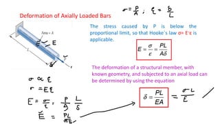


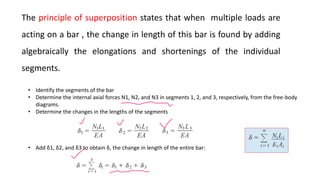


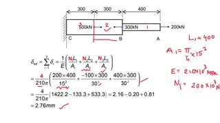
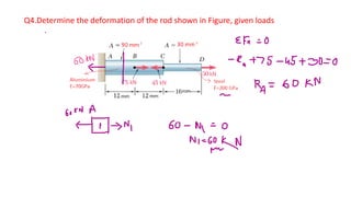
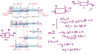
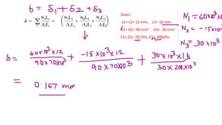

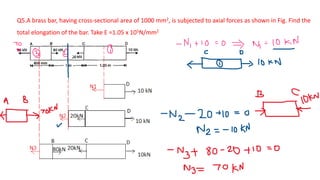


The document discusses deformation of axially loaded bars. It defines key terms like stress, strain, Hooke's law, stiffness, compliance, and axial rigidity. It also describes how to calculate deformation of bars with multiple loads or non-uniform properties by dividing the bar into segments and using the principle of superposition. Several example problems are given to illustrate calculating deformation of bars under different loading conditions.


