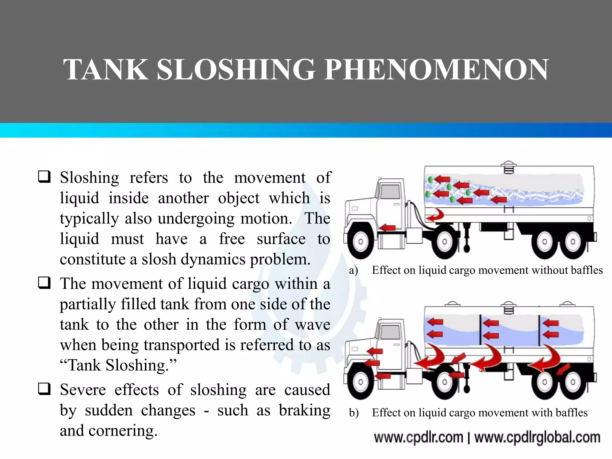
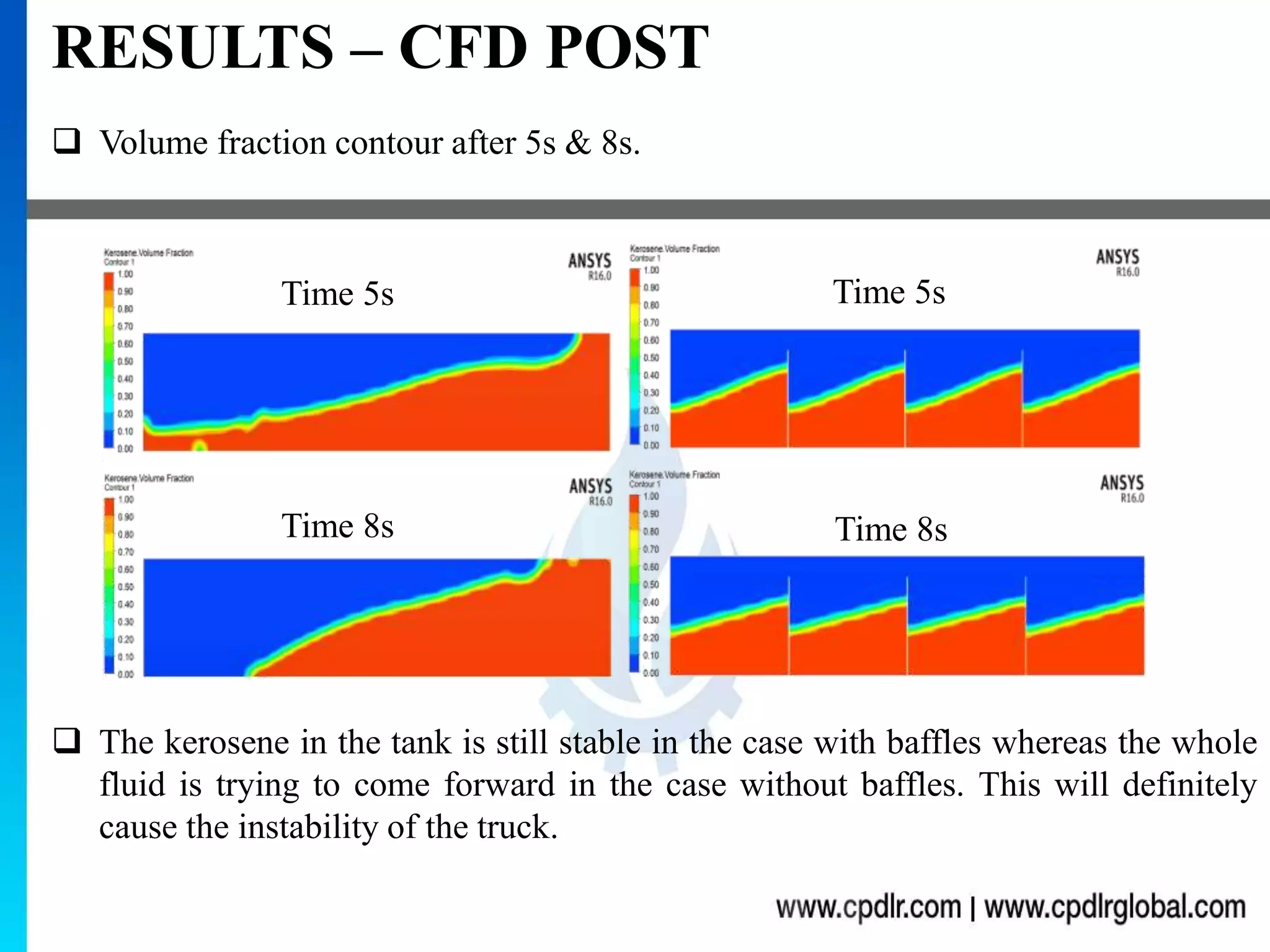
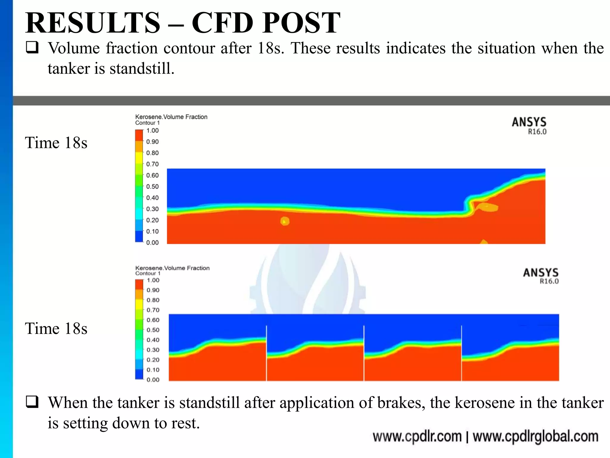
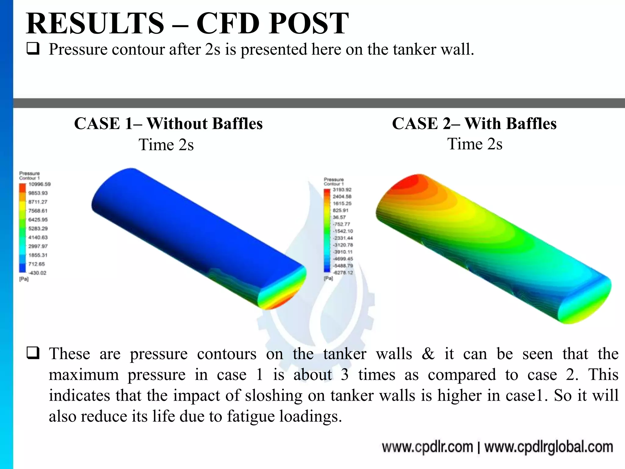
TANK SLOSHING SIMULATION
USING VOF MULTIPHASE MODEL
ANSYS FLUENT
a) Effect on liquid cargo movement without baffles
b) Effect on liquid cargo movement with baffles
TANK SLOSHING PHENOMENON
 Sloshing refers to the movement of
liquid inside another object which is
typically also undergoing motion. The
liquid must have a free surface to
constitute a slosh dynamics problem.
 The movement of liquid cargo within a
partially filled tank from one side of the
tank to the other in the form of wave
when being transported is referred to as
“Tank Sloshing.”
 Severe effects of sloshing are caused
by sudden changes - such as braking
and cornering.
INDUSTRIAL NEED
 Liquid cargo sloshing strongly affects the
directional stability and safety performance
of highway tank vehicles in a highly
adverse manner.
 Hydrodynamic forces and moments arising
from liquid cargo oscillations in the tank
under steering and braking maneuvers
reduce the stability and controllability of
partially-filled resulting into rollover or
jackknifing.
 Proper design of baffles is necessary to
avoid such hazardous accidents.
PROBLEM STATEMENT
 An elliptical tank which is half-filled
with kerosene is undergoing following
motions :-
1. First, accelerating at 2 m/s2 for 10.5
seconds,
2. Then decelerating at 4.2m/s2 for 5
seconds to come at rest &
3. Then standstill for 3 seconds.
 Study requires simulation of oil tank
under such conditions in the absence of
baffles first (CASE1) & then reducing
the sloshing intensity by providing
baffles (CASE2).
0
5
10
15
20
25
0 5 10 15 20
Time (s)
Velocity Vs Time Chart
Velocity(m/s)
GEOMETRY
 The 3D geometry of the elliptical tank was created in Design Modeler.
 Length of the tank (L) = 9.6m
 Length of the major axis (Lma)= 2.85m
 Length of minor axis (Lmi)= 1.81m
 Volume of tank = 43.35m3
 Filled volume of kerosene =21.675m3
 Baffle height is taken 0.8 times tank height.
KEROSENE
AIR
Lma
Lmi
L L/4
CASE 1– Without Baffles CASE 2– With Baffles
MESH
 A high quality hexahedral grid was
generated using the slicing technique in
ANSYS Mesh Tool. Conformal mesh
between the sliced parts were
confirmed.
 Total number of elements achieved was
40,106. The mesh is kept coarse
otherwise the computational time
would go much higher.
 The maximum skewness was 0.65
which indicates that the quality of the
grid is very good.
NUMERICAL SETUP
Properties Air Kerosene
Density (Kg/m3) 1.225 780
Viscosity (Kg/m-s) 0.000017894 0.0024
 Vof (Volume Of Fluid) is the most suitable multiphase model for this case
because the two participating fluids are immiscible & there will be clear
interface between them.
 Air is used as primary phase and the kerosene was used as secondary
phase.
 Standard k-epsilon turbulence model was used for the case.
 Energy equation was not used as the case was assumed isothermal and
there were no heat exchange.
 The transient simulation was run for 18.5s with time-dependent velocity.
 In the contour of volume fraction, the red color indicates the kerosene & the blue
color indicates the air.
RESULTS – CFD POST
 Due to acceleration, the kerosene in the container is moving forward in both
cases. But due to presence of baffles in second case the kerosene is much stable
as compared to the first case. It can be clearly seen in the pictures below.
 These are the volume fraction contours after 1s & 2s of acceleration.
CASE 1– Without Baffles CASE 2– With Baffles
Time 1s
Time 2s
Time 1s
Time 2s
 Volume fraction contour after 5s & 8s.
RESULTS – CFD POST
 The kerosene in the tank is still stable in the case with baffles whereas the whole
fluid is trying to come forward in the case without baffles. This will definitely
cause the instability of the truck.
Time 5s
Time 8s
Time 5s
Time 8s
 Volume fraction contour after 13s & 15s. These results indicates the situation
after application of brakes. Kerosene is suddenly moving backward due to change
in inertia of truck.
RESULTS – CFD POST
 The kerosene in the tank is still stable in the case with baffles whereas the whole
fluid is trying to move backward in the case without baffles. So we can say that
the center of gravity of truck is drastically shifting from time to time in case
without baffles. So this leads to instability & difficulty in handling.
Time 13s
Time 15s
Time 13s
Time 15s
 Volume fraction contour after 18s. These results indicates the situation when the
tanker is standstill.
RESULTS – CFD POST
 When the tanker is standstill after application of brakes, the kerosene in the tanker
is setting down to rest.
Time 18s
Time 18s
 Pressure contour after 2s is presented here on the tanker wall.
RESULTS – CFD POST
 These are pressure contours on the tanker walls & it can be seen that the
maximum pressure in case 1 is about 3 times as compared to case 2. This
indicates that the impact of sloshing on tanker walls is higher in case1. So it will
also reduce its life due to fatigue loadings.
Time 2s Time 2s
CASE 1– Without Baffles CASE 2– With Baffles
 Pressure chart between Maximum Pressure & Time on the tanker walls.
RESULTS – CFD POST
 From the chart it can be seen that the impact of sloshing in case 1 is always
higher as compared to case 2. After breaking, the maximum impact on the wall
can be observed.
 Sloshing phenomenon in oil tanker was simulated using Vof (Volume Of
Fluid) multiphase model in ANSYS Fluent.
 Volume fraction of kerosene oil was studied at different time for both the
cases & it was concluded that the stability of the tanker can be increased by
the introduction of baffles in the tanker.
 The maximum pressure on the walls were also studies with time and it was
concluded that the pressure on the wall can be reduced by application of
baffles.
CONCLUSION

Tank Sloshing Simulation

  • 1.
    TANK SLOSHING SIMULATION USINGVOF MULTIPHASE MODEL ANSYS FLUENT
  • 2.
    a) Effect onliquid cargo movement without baffles b) Effect on liquid cargo movement with baffles TANK SLOSHING PHENOMENON  Sloshing refers to the movement of liquid inside another object which is typically also undergoing motion. The liquid must have a free surface to constitute a slosh dynamics problem.  The movement of liquid cargo within a partially filled tank from one side of the tank to the other in the form of wave when being transported is referred to as “Tank Sloshing.”  Severe effects of sloshing are caused by sudden changes - such as braking and cornering.
  • 3.
    INDUSTRIAL NEED  Liquidcargo sloshing strongly affects the directional stability and safety performance of highway tank vehicles in a highly adverse manner.  Hydrodynamic forces and moments arising from liquid cargo oscillations in the tank under steering and braking maneuvers reduce the stability and controllability of partially-filled resulting into rollover or jackknifing.  Proper design of baffles is necessary to avoid such hazardous accidents.
  • 4.
    PROBLEM STATEMENT  Anelliptical tank which is half-filled with kerosene is undergoing following motions :- 1. First, accelerating at 2 m/s2 for 10.5 seconds, 2. Then decelerating at 4.2m/s2 for 5 seconds to come at rest & 3. Then standstill for 3 seconds.  Study requires simulation of oil tank under such conditions in the absence of baffles first (CASE1) & then reducing the sloshing intensity by providing baffles (CASE2). 0 5 10 15 20 25 0 5 10 15 20 Time (s) Velocity Vs Time Chart Velocity(m/s)
  • 5.
    GEOMETRY  The 3Dgeometry of the elliptical tank was created in Design Modeler.  Length of the tank (L) = 9.6m  Length of the major axis (Lma)= 2.85m  Length of minor axis (Lmi)= 1.81m  Volume of tank = 43.35m3  Filled volume of kerosene =21.675m3  Baffle height is taken 0.8 times tank height. KEROSENE AIR Lma Lmi L L/4 CASE 1– Without Baffles CASE 2– With Baffles
  • 6.
    MESH  A highquality hexahedral grid was generated using the slicing technique in ANSYS Mesh Tool. Conformal mesh between the sliced parts were confirmed.  Total number of elements achieved was 40,106. The mesh is kept coarse otherwise the computational time would go much higher.  The maximum skewness was 0.65 which indicates that the quality of the grid is very good.
  • 7.
    NUMERICAL SETUP Properties AirKerosene Density (Kg/m3) 1.225 780 Viscosity (Kg/m-s) 0.000017894 0.0024  Vof (Volume Of Fluid) is the most suitable multiphase model for this case because the two participating fluids are immiscible & there will be clear interface between them.  Air is used as primary phase and the kerosene was used as secondary phase.  Standard k-epsilon turbulence model was used for the case.  Energy equation was not used as the case was assumed isothermal and there were no heat exchange.  The transient simulation was run for 18.5s with time-dependent velocity.
  • 8.
     In thecontour of volume fraction, the red color indicates the kerosene & the blue color indicates the air. RESULTS – CFD POST  Due to acceleration, the kerosene in the container is moving forward in both cases. But due to presence of baffles in second case the kerosene is much stable as compared to the first case. It can be clearly seen in the pictures below.  These are the volume fraction contours after 1s & 2s of acceleration. CASE 1– Without Baffles CASE 2– With Baffles Time 1s Time 2s Time 1s Time 2s
  • 9.
     Volume fractioncontour after 5s & 8s. RESULTS – CFD POST  The kerosene in the tank is still stable in the case with baffles whereas the whole fluid is trying to come forward in the case without baffles. This will definitely cause the instability of the truck. Time 5s Time 8s Time 5s Time 8s
  • 10.
     Volume fractioncontour after 13s & 15s. These results indicates the situation after application of brakes. Kerosene is suddenly moving backward due to change in inertia of truck. RESULTS – CFD POST  The kerosene in the tank is still stable in the case with baffles whereas the whole fluid is trying to move backward in the case without baffles. So we can say that the center of gravity of truck is drastically shifting from time to time in case without baffles. So this leads to instability & difficulty in handling. Time 13s Time 15s Time 13s Time 15s
  • 11.
     Volume fractioncontour after 18s. These results indicates the situation when the tanker is standstill. RESULTS – CFD POST  When the tanker is standstill after application of brakes, the kerosene in the tanker is setting down to rest. Time 18s Time 18s
  • 12.
     Pressure contourafter 2s is presented here on the tanker wall. RESULTS – CFD POST  These are pressure contours on the tanker walls & it can be seen that the maximum pressure in case 1 is about 3 times as compared to case 2. This indicates that the impact of sloshing on tanker walls is higher in case1. So it will also reduce its life due to fatigue loadings. Time 2s Time 2s CASE 1– Without Baffles CASE 2– With Baffles
  • 13.
     Pressure chartbetween Maximum Pressure & Time on the tanker walls. RESULTS – CFD POST  From the chart it can be seen that the impact of sloshing in case 1 is always higher as compared to case 2. After breaking, the maximum impact on the wall can be observed.
  • 14.
     Sloshing phenomenonin oil tanker was simulated using Vof (Volume Of Fluid) multiphase model in ANSYS Fluent.  Volume fraction of kerosene oil was studied at different time for both the cases & it was concluded that the stability of the tanker can be increased by the introduction of baffles in the tanker.  The maximum pressure on the walls were also studies with time and it was concluded that the pressure on the wall can be reduced by application of baffles. CONCLUSION