1. A spring is an elastic element that deflects under load and returns to its original shape when the load is removed. Springs are commonly used to absorb shocks, measure forces, store energy, and apply or control motion.
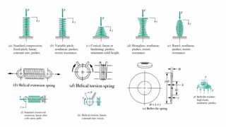
2. The main types of springs are helical coil springs, torsion bar springs, leaf springs, volute springs, pneumatic springs, and Belleville springs. Helical coil springs can be compression or extension springs and can have standard, variable pitch, or conical coil designs.
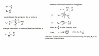
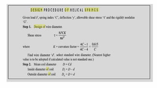
3. The stress, deflection, and rate of springs is calculated based on factors like wire diameter, mean coil diameter, shear modulus, and spring index. Higher spring indices provide