1) Optical amplifiers are needed in long-distance optical communications to compensate for signal power loss and pulse broadening.
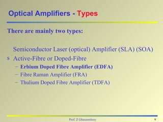
2) There are two main types of optical amplifiers - semiconductor optical amplifiers and doped-fiber amplifiers such as erbium doped fiber amplifiers.
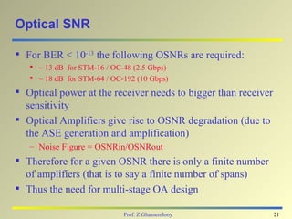
3) Optical amplifiers amplify signals through stimulated emission and introduce noise in the form of amplified spontaneous emission. They must have high gain, wide bandwidth, low noise figure and high saturation power to be used effectively in optical communication systems.
![Optical Amplifiers: Multi-Stage
Er3+
Doped Fiber
Input Signal Output Signal
Optical
Isolator
Pump Pump
1st Active stage co-pumped: 2nd stage counter-pumped:
optimized for low noise figure optimized for high output power
NF 1st/2nd stage = Pin - SNRo [dB] - 10 Log (hc2∆λ / λ3)
NFtotal = NF1+NF2/G1
Prof. Z Ghassemlooy 22](https://image.slidesharecdn.com/opticalamp-120313130149-phpapp01/85/Opticalamp-22-320.jpg)