Downloaded 199 times

![Internship July 13 – July 24 2016
42
Keltron Controls -Aroor
REFERENCES
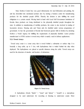
[1] The Class-room sessions & Practical sessions in Keltron Controls Aroor.
[2] website- www.keltron.org/aboutkeltron.php
[3] website- https://en.wikipedia.org/wiki/K._P._P._Nambiar](https://image.slidesharecdn.com/internshipreportmain-160912070556/85/Internship-report-main-42-320.jpg)

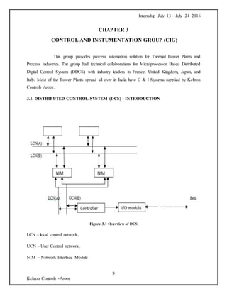
Keltron Controls was established in 1979 as the control and instrumentation division of KSEDC to introduce state-of-the-art control and instrumentation technology to India's power and process industries. It commenced operations through a technical collaboration with Controle Bailey of France. For many years, Keltron Controls specialized in design, manufacturing, software, erection and commissioning of control and instrumentation systems. However, due to industry reforms in the 1990s, the control and instrumentation business declined. Keltron Controls restructured into four strategic business units to utilize infrastructure - Control and Instrumentation, Pneumatic Products, Information Technology, and Strategic Services Group. It continues to provide automation solutions while diversifying into new areas like defense, shipping instrumentation


