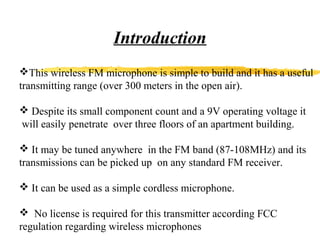
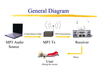
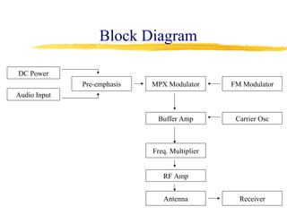
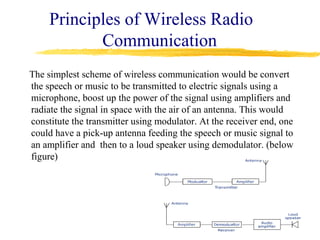
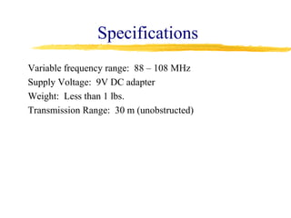
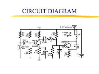
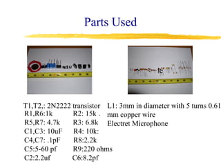
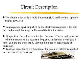
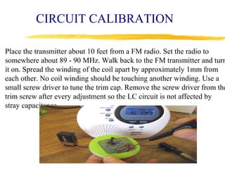
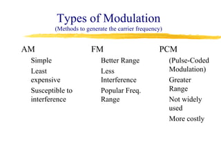
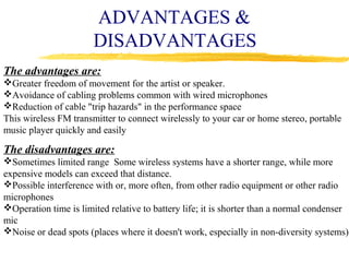
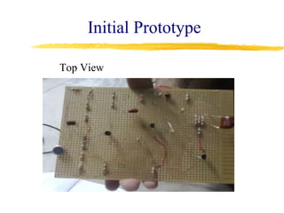
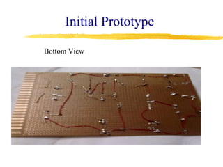
Wireless FM Microphone


                  EFFORTS BY:
                  DEEPESH
                  KHANEJA
Introduction
This wireless FM microphone is simple to build and it has a useful
transmitting range (over 300 meters in the open air).

 Despite its small component count and a 9V operating voltage it
will easily penetrate over three floors of an apartment building.

 It may be tuned anywhere in the FM band (87-108MHz) and its
transmissions can be picked up on any standard FM receiver.

 It can be used as a simple cordless microphone.

 No license is required for this transmitter according FCC
regulation regarding wireless microphones
Project Description
Wireless FM transmitter is a device
that will enable audio playback
through any FM stereo.

Device will transmit any audio
output to any FM stereo located
within the operating range.

Allows the user to listen to music
through higher quality speakers vs
standard computer speakers.
General Diagram


            3.5mm Stereo Cable                FM Transmission


MP3 Audio                         MP3 Tx                         Receiver
 Source

                                                                Music

                                     User
                                 (Doing the worm)
Block Diagram

DC Power
              Pre-emphasis   MPX Modulator      FM Modulator
Audio Input


                              Buffer Amp         Carrier Osc


                             Freq. Multiplier


                                RF Amp


                                Antenna           Receiver
WIRELESS TECHNOLOGY
The concept of having no wires connecting devices to each other is appealing
  for several reasons:
 Wires can be complicated and untidy, having no wires is pleasing.
 Wireless operations permits services, such as long range communications,
  that are impossible or impractical to implement with the use of wires.
 The term is commonly used in the telecommunications industry to refer to
  telecommunications systems (e.g. radio transmitters and receivers,
  computer networks, ) which use some form of energy (e.g. radio frequency
  (RF) etc.) to transfer information without the use of wires.
Principles of Wireless Radio
            Communication
The simplest scheme of wireless communication would be convert
the speech or music to be transmitted to electric signals using a
microphone, boost up the power of the signal using amplifiers and
radiate the signal in space with the air of an antenna. This would
constitute the transmitter using modulator. At the receiver end, one
could have a pick-up antenna feeding the speech or music signal to
an amplifier and then to a loud speaker using demodulator. (below
figure)
Specifications
Variable frequency range: 88 – 108 MHz
Supply Voltage: 9V DC adapter
Weight: Less than 1 lbs.
Transmission Range: 30 m (unobstructed)
CIRCUIT DIAGRAM
Parts Used


                                          le


T1,T2,: 2N2222 transistor L1: 3mm in diameter with 5 turns 0.61
R1,R6:1k       R2: 15k . mm copper wire
R5,R7: 4.7k    R3: 6.8k Electret Microphone
C1,C3: 10uF R4: 10k:
C4,C7: .1pF    R8:2.2k
C5:5-60 pf     R9:220 ohms
C2:2.2uf       C6:8.2pf
Circuit Description
The circuit is basically a radio frequency (RF) oscillator that operates
 around 100 MHz.

 Audio picked up & amplified by the electret microphone is fed into
the audio amplifier stage built around the first transistor.

 Output from the collector is fed into the base of the second transistor
   where it modulates the resonant frequency of the tank circuit (the 5
turn coil and the trimcap) by varying the junction capacitance of
transistor.
 Junction capacitance is a function of the potential difference applied
to the base of the transistor.
ELECTRET MICROPHONE


An electret is a permanently charged dielectric.

 Ceramic material is used as part of the dielectric of a capacitor in
which the diaphram of the microphone forms one plate.

Sound pressure moves one of its plates. The movement of the plate
changes the capacitance.

The electret capacitor is connected to an FET amplifier.

 These microphones are small, have excellent sensitivity, a wide
frequency response and a very low cost.
RESONANT FREQUENCY
ASSEMBLY INSTRUCTION

The electret microphone should be inserted with the pin connected to the metal case
connected to the negative rail (that is, to the ground or zero voltage side of the circuit).

The coil should be about 3mm in diameter and 5 turns.

.After the coil is soldered into place spread the coils apart about 0.5 to 1mm so that
they don't touch.

 Tx frequency is adjusted by varying trim capacitor.

 Connect a half or quarter wavelength antenna (length of wire) to the aerial point..
CIRCUIT CALIBRATION

Place the transmitter about 10 feet from a FM radio. Set the radio to
somewhere about 89 - 90 MHz. Walk back to the FM transmitter and turn
it on. Spread the winding of the coil apart by approximately 1mm from
each other. No coil winding should be touching another winding. Use a
small screw driver to tune the trim cap. Remove the screw driver from the
trim screw after every adjustment so the LC circuit is not affected by
stray capacitance.
APPLICATIONS

Wireless FM microphones are widely used in the

entertainment industry,
television broadcasting,
and public speaking to allow public speakers,
interviewers, performers, and entertainers to move about freely
while using a microphone to amplify their voices.
Types of Modulation
         (Methods to generate the carrier frequency)


AM                     FM                         PCM
 Simple                    Better Range                (Pulse-Coded
 Least                     Less                        Modulation)
 expensive                 Interference                Greater
 Susceptible to            Popular Freq.               Range
 interference              Range                       Not widely
                                                       used
                                                       More costly
ADVANTAGES &
                       DISADVANTAGES
The advantages are:
Greater freedom of movement for the artist or speaker.
Avoidance of cabling problems common with wired microphones
Reduction of cable "trip hazards" in the performance space
This wireless FM transmitter to connect wirelessly to your car or home stereo, portable
music player quickly and easily

The disadvantages are:
Sometimes limited range Some wireless systems have a shorter range, while more
expensive models can exceed that distance.
Possible interference with or, more often, from other radio equipment or other radio
microphones
Operation time is limited relative to battery life; it is shorter than a normal condenser
mic
Noise or dead spots (places where it doesn't work, especially in non-diversity systems)
Initial Prototype

Top View
Initial Prototype

Bottom View
Complications

Weak signal of the receiver input
Variable inductor difficult to tune
Several components very sensitive to external
interference
Excess noise on the transmitted signal
Solution to FM Noise

Current Solutions
  Re-adjust the variable inductor
  Re-adjust the variable resistor
  Check proper voltage input


Additional Solution
  Mount the components on a PCB
THANK YOU

WIRELESS FM Microphone

  • 1.
    Wireless FM Microphone EFFORTS BY: DEEPESH KHANEJA
  • 2.
    Introduction This wireless FMmicrophone is simple to build and it has a useful transmitting range (over 300 meters in the open air).  Despite its small component count and a 9V operating voltage it will easily penetrate over three floors of an apartment building.  It may be tuned anywhere in the FM band (87-108MHz) and its transmissions can be picked up on any standard FM receiver.  It can be used as a simple cordless microphone.  No license is required for this transmitter according FCC regulation regarding wireless microphones
  • 3.
    Project Description Wireless FMtransmitter is a device that will enable audio playback through any FM stereo. Device will transmit any audio output to any FM stereo located within the operating range. Allows the user to listen to music through higher quality speakers vs standard computer speakers.
  • 4.
    General Diagram 3.5mm Stereo Cable FM Transmission MP3 Audio MP3 Tx Receiver Source Music User (Doing the worm)
  • 5.
    Block Diagram DC Power Pre-emphasis MPX Modulator FM Modulator Audio Input Buffer Amp Carrier Osc Freq. Multiplier RF Amp Antenna Receiver
  • 6.
    WIRELESS TECHNOLOGY The conceptof having no wires connecting devices to each other is appealing for several reasons:  Wires can be complicated and untidy, having no wires is pleasing.  Wireless operations permits services, such as long range communications, that are impossible or impractical to implement with the use of wires.  The term is commonly used in the telecommunications industry to refer to telecommunications systems (e.g. radio transmitters and receivers, computer networks, ) which use some form of energy (e.g. radio frequency (RF) etc.) to transfer information without the use of wires.
  • 7.
    Principles of WirelessRadio Communication The simplest scheme of wireless communication would be convert the speech or music to be transmitted to electric signals using a microphone, boost up the power of the signal using amplifiers and radiate the signal in space with the air of an antenna. This would constitute the transmitter using modulator. At the receiver end, one could have a pick-up antenna feeding the speech or music signal to an amplifier and then to a loud speaker using demodulator. (below figure)
  • 8.
    Specifications Variable frequency range:88 – 108 MHz Supply Voltage: 9V DC adapter Weight: Less than 1 lbs. Transmission Range: 30 m (unobstructed)
  • 9.
  • 10.
    Parts Used le T1,T2,: 2N2222 transistor L1: 3mm in diameter with 5 turns 0.61 R1,R6:1k R2: 15k . mm copper wire R5,R7: 4.7k R3: 6.8k Electret Microphone C1,C3: 10uF R4: 10k: C4,C7: .1pF R8:2.2k C5:5-60 pf R9:220 ohms C2:2.2uf C6:8.2pf
  • 11.
    Circuit Description The circuitis basically a radio frequency (RF) oscillator that operates around 100 MHz.  Audio picked up & amplified by the electret microphone is fed into the audio amplifier stage built around the first transistor.  Output from the collector is fed into the base of the second transistor where it modulates the resonant frequency of the tank circuit (the 5 turn coil and the trimcap) by varying the junction capacitance of transistor.  Junction capacitance is a function of the potential difference applied to the base of the transistor.
  • 12.
    ELECTRET MICROPHONE An electretis a permanently charged dielectric.  Ceramic material is used as part of the dielectric of a capacitor in which the diaphram of the microphone forms one plate. Sound pressure moves one of its plates. The movement of the plate changes the capacitance. The electret capacitor is connected to an FET amplifier.  These microphones are small, have excellent sensitivity, a wide frequency response and a very low cost.
  • 13.
  • 14.
    ASSEMBLY INSTRUCTION The electretmicrophone should be inserted with the pin connected to the metal case connected to the negative rail (that is, to the ground or zero voltage side of the circuit). The coil should be about 3mm in diameter and 5 turns. .After the coil is soldered into place spread the coils apart about 0.5 to 1mm so that they don't touch.  Tx frequency is adjusted by varying trim capacitor.  Connect a half or quarter wavelength antenna (length of wire) to the aerial point..
  • 15.
    CIRCUIT CALIBRATION Place thetransmitter about 10 feet from a FM radio. Set the radio to somewhere about 89 - 90 MHz. Walk back to the FM transmitter and turn it on. Spread the winding of the coil apart by approximately 1mm from each other. No coil winding should be touching another winding. Use a small screw driver to tune the trim cap. Remove the screw driver from the trim screw after every adjustment so the LC circuit is not affected by stray capacitance.
  • 16.
    APPLICATIONS Wireless FM microphonesare widely used in the entertainment industry, television broadcasting, and public speaking to allow public speakers, interviewers, performers, and entertainers to move about freely while using a microphone to amplify their voices.
  • 17.
    Types of Modulation (Methods to generate the carrier frequency) AM FM PCM Simple Better Range (Pulse-Coded Least Less Modulation) expensive Interference Greater Susceptible to Popular Freq. Range interference Range Not widely used More costly
  • 18.
    ADVANTAGES & DISADVANTAGES The advantages are: Greater freedom of movement for the artist or speaker. Avoidance of cabling problems common with wired microphones Reduction of cable "trip hazards" in the performance space This wireless FM transmitter to connect wirelessly to your car or home stereo, portable music player quickly and easily The disadvantages are: Sometimes limited range Some wireless systems have a shorter range, while more expensive models can exceed that distance. Possible interference with or, more often, from other radio equipment or other radio microphones Operation time is limited relative to battery life; it is shorter than a normal condenser mic Noise or dead spots (places where it doesn't work, especially in non-diversity systems)
  • 19.
  • 20.
  • 21.
    Complications Weak signal ofthe receiver input Variable inductor difficult to tune Several components very sensitive to external interference Excess noise on the transmitted signal
  • 22.
    Solution to FMNoise Current Solutions Re-adjust the variable inductor Re-adjust the variable resistor Check proper voltage input Additional Solution Mount the components on a PCB
  • 23.