1. What is a Transmitter IC?
A transmitter (or radio transmitter) is an electronic device which produces radio waves with the help of an antenna.
A transmitter generates a radio frequency current applied to the antenna, which in turn radiates radio waves. A
transmitter generates radio waves for communication, radar and navigational purposes. A transmitter can either be
a separate piece of electronic equipment or an integrated circuit (IC) within another electronic device. Most
transmitters are used for radio communication of information over a certain distance. The information that is provided
to the transmitter is in the form of an electronic signal. This includes audio from a microphone, video from a TV
camera, or a digital signal for wireless networking devices. The transmitter combines the information signal that is
to be carried with the RF signal which generates the radio waves (the carrier). This is called modulation. In an FM
transmitter, the information is added to the radio signal by slightly varying the radio signal's frequency. In an AM
transmitter, it is added by varying its amplitude. Several other types of modulation are also used. ICs, or integrated
circuits, allow high performance circuits to be built at lesser costs and with significant amounts of space savings.
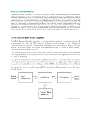
Radio Transmitter Block Diagram
This block diagram of a radio transmitter in a communication system is very simple and basic. It
is generalised for AM and FM types of modulation, and consists of four subsystems.
Communication is the transfer of meaningful information from one location to another. We start
with the conversion of sound waves in the air into electrical energy. A transducer, which is usually
a microphone, does this job very well.
The carrier wave generator is an oscillator, which produces pure un-modulated sine waves in the
radio frequency range. It usually consists of a tuned oscillator circuit that produces a carrier wave
of a specific frequency.
The signal from the carrier wave generator, and transducer, feeds a modulator, which encodes the
carrier signal with the information we wish to send. There are two types of modulation methods;
in AM, the amplitude of the carrier modulates, whilst in FM the frequency of the carrier modulates.
The transmitter block is usually responsible for generating electromagnetic waves that travel
through the air.
2. AM Transmitter
In order to better understand the way the radio transmitter works, block - diagram of
a simple AM (amplitude modulated) signal transmitter is shown on Pic. The
amplitude modulation is being performed in a stage called the modulator. Two
signals are entering it: high frequency signal called the carrier (or the signal carrier),
being created into the HF oscillator and amplified in the HF amplifier to the required
signal level, and the low frequency (modulating) signal coming from the microphone
or some other LF signal source (cassette player, record player, CD player etc.), being
amplified in the LF amplifier. On modulator's output the amplitude modulated signal
UAM is acquired. This signal is then amplified in the power amplifier, and then led
to the emission antenna.
The shape and characteristics of the AM carrier, being taken from the HF amplifier
into the modulator, are shown on Pic. As you can see, it is a HF voltage of constant
amplitude US and frequency fS. On Pic. the LF signal that appears at the input of
the modulator at the moment t0 is shown. With this signal the modulation of the
carrier's amplitude is being performed, therefore it is being called the modulating
signal. The shape of the AM signal exiting the modulator is shown on Pic. From the
3. point t0 this voltage has the same shape as that on Pic. From the moment t0 the
amplitude of AM signal is being changed in accordance with the current value of the
modulating signal, in such a way that the signal envelope (fictive line connecting the
voltage peaks) has the same shape as the modulating signal.
Let's take a look at a practical example. Let the LF signal on Pic. be, say, an electrical
image of the tone being created by some musical instrument, and that the time gap
between the points t0 and t2 is 1 ms. Suppose that carrier frequency is fS=1 MHz
(approximately the frequency of radio Kladovo, exact value is 999 kHz). In that case,
in period from t0 till t2 signals us on Pic. and AM on should make a thousand
oscillations and not just eighteen, as shown in the picture. Then It is clear that it isn't
possible to draw a realistic picture, since all the lines would connect into a dark spot.
The true picture of AM signal from this example is given on Pic. That is the picture
that appears on screen of the oscilloscope, connected on the output of the modulator:
light coloured lines representing the AM signal have interconnected, since they are
thicker than the gap between them.
Block - diagram on Pic is a simplified schematic of an AM transmitter. In reality
there are some additional stages in professional transmitters that provide the
necessary work stability, transmitter power supply, cooling for certain stages etc.
For simple use, however, even simpler block diagrams exist, making the completion
of an ordinary AM transmitter possible with just a few electronic components.
4. FM Transmitter
Block diagram of an FM (frequency modulated) transmitter is given on Pic.2.4.
Information being transferred, i.e. the modulating signal, is a signal from some LF
source. it is being amplified in LF amplifier and then led into the HF oscillator, where
the carrier signal is being created. The carrier is a HF voltage of constant amplitude,
whose frequency is, in the absence of modulating signal, equal to the transmitter's
5. carrier frequency fS. In the oscillatory circuit of the HF oscillator a varicap
(capacitive) diode is located. It is a diode whose capacitance depends upon the
voltage between its ends, so when being exposed to LF voltage, its capacitance is
changing in accordance with this voltage. Due to that frequency of the oscillator is
also changing, i.e. the frequency modulation is being obtained. The FM signal from
the HF oscillator is being proceeded to the power amplifier that provides the
necessary output power of the transmission signal. Voltage shapes in FM transmitter
are given on Pic.2.5. Pic.2.5-a shows the LF modulating signal. The frequency
modulation begins at moment t0 and the transmission frequency begins to change,
as shown on Pic.2.5-b: Whilst current value of the LF signal is raising so is the
trasmitter frequency, and when it is falling the frequency is also falling. As seen on
Pic.2.5-c, the information (LF signal) is being implied in frequency change of the
carrier.
The carrier frequencies of the radio difusion FM transmitters (that emmit the
program for "broad audience") are placed in the waveband from 88 MHz til 108
MHz, the maximum frequency shift of the transmitter (during the modulation) being
±75 kHz. Because of that the FM signal should be drawn much "thicker", but it
would result in a black-square-shaped picture.
6.
7. AM radio broad cast Receiver
AM broadcasting is the process of radio broadcasting using amplitude modulation
(AM). AM was the first method of impressing sound on a radio signal and is still
widely used today. Commercial and public AM broadcasting is authorized in the
medium wave band worldwide, and also in parts of the long wave and short wave
bands. Radio broadcasting was made possible by the invention of the amplifying
vacuum tube, the Audion(triode), by Lee de Forest in 1906, which led to the
development of inexpensive vacuum tube AM radio receivers and transmitters
during World War I. Commercial AM broadcasting developed from amateur
broadcasts around 1920, and was the only commercially important form of radio
broadcasting until FM broadcasting began after World War II. This period is known
as the "Golden Age of Radio". Today, AM competes with FM, as well as with
various digital radio broadcasting services distributed from terrestrial and satellite
transmitters. In many countries the higher levels of interference experienced with
AM transmission have caused AM broadcasters to specialize in news, sports and talk
radio, leaving transmission of music mainly to FM and digital broadcasters.
AM radio technology is simpler than frequency modulated (FM) radio, Digital
Audio Broadcasting (DAB), satellite radio or HD (digital) radio. An AM receiver
detects amplitude variations in the radio waves at a particular frequency.
It then amplifies changes in the signal voltage to drive aloudspeaker or earphones.
The earliest crystal radio receivers used a crystal diode detector with no
amplification, and required no power source other than the radio signal itself.
8. In North American broadcasting practice, transmitter power input to the antenna for
commercial AM stations ranges from about 250 to 50,000watts. Experimental
licenses were issued for up to 500,000 watts radiated power, for stations intended
for wide-area communication during disasters. One such superstation was Cincinnati
station WLW, which used such power on occasion before World War II. WLW's
superpower transmitter still exists at the station's suburban transmitter site, but it was
decommissioned in the early 1940s and no current commercial broadcaster in the
U.S. or Canada is authorized for such power levels. Some other countries do
authorize higher power operation (for example the Mexican station XERF formerly
operated at 250,000 watts). Antenna design must consider the coverage desired and
stations may be required, based on the terms of their license, to directionalize their
transmitted signal to avoid interfering with other stations operating on the same
frequency.
Radio receiver
In the early days of what is now known as early radio transmissions, say about 100
years ago, signals were generated by various means but only up to the L.F. region.
Communication was by way of morse code much in the form that a short
transmission denoted a dot (dit) and a longer transmission was a dash (dah). This
was the only form of radio transmission until the 1920's and only of use to the
military, commercial telegraph companies and amateur experimenters.
9. Then it was discovered that if the amplitude (voltage levels - plus and minus about
zero) could be controlled or varied by a much lower frequency such as A.F. then real
intelligence could be conveyed e.g. speech and music. This process could be easily
reversed by simple means at the receiving end by using diode detectors. This is called
modulation and obviously in this case amplitude modulation or A.M.
This discovery spawned whole new industries and revolutionized the world of
communications. Industries grew up manufacturing radio parts, receiver
manufacturers, radio stations, news agencies, recording industries etc.
Disadvantages to A.M. radio
Firstly because of the modulation process we generate at least two copies of the
intelligence plus the carrier. For example consider a local radio station transmitting
on say 900 Khz. This frequency will be very stable and held to a tight tolerance. To
suit our discussion and keep it as simple as possible we will have the transmission
modulated by a 1000 Hz or 1Khz tone.
At the receiving end 3 frequencies will be available. 900 Khz, 901 Khz and 899 Khz
i.e. the original 900 Khz (the carrier) plus and minus the modulating frequency which
are called side bands. For very simple receivers such as a cheap transistor radio we
only require the original plus either one of the side bands. The other one is a total
waste. For sophisticated receivers one side band can be eliminated.
The net effect is A.M. radio stations are spaced 10 Khz apart (9 kHz in Australia)
e.g. 530 Khz...540 Khz...550 Khz. This spacing could be reduced and nearly twice
as many stations accommodated by deleting one side band. Unfortunately the
increased cost of receiver complexity forbids this but it certainly is feasible.
10. AM Transmitter :
Transmitters that transmit AM signals are known as AM transmitters. These transmitters are used
in medium wave (MW) and short wave (SW) frequency bands for AM broadcast. The MW band
has frequencies between 550 KHz and 1650 KHz, and the SW band has frequencies ranging
from 3 MHz to 30 MHz. The two types of AM transmitters that are used based on their
transmitting powers are:
High Level
Low Level
High level transmitters use high level modulation, and low level transmitters use low level
modulation. The choice between the two modulation schemes depends on the transmitting power
of the AM transmitter. In broadcast transmitters, where the transmitting power may be of the
order of kilowatts, high level modulation is employed. In low power transmitters, where only a
few watts of transmitting power are required , low level modulation is used.
High-Level and Low-Level
Transmitters
Below figure's show the block diagram of high-level and low-level transmitters. The basic
difference between the two transmitters is the power amplification of the carrier and modulating
signals.
Figure (a) shows the block diagram of high-level AM transmitter.
In high-level transmission, the powers of the carrier and modulating signals are amplified before
applying them to the modulator stage, as shown in figure (a). In low-level modulation, the
powers of the two input signals of the modulator stage are not amplified. The required
transmitting power is obtained from the last stage of the transmitter, the class C power amplifier.
11. The various sections of the figure (a) are:
Carrier oscillator
Buffer amplifier
Frequency multiplier
Power amplifier
Audio chain
Modulated class C power amplifier
Carrier oscillator
The carrier oscillator generates the carrier signal, which lies in the RF range. The frequency of
the carrier is always very high. Because it is very difficult to generate high frequencies with good
frequency stability, the carrier oscillator generates a sub multiple with the required carrier
frequency. This sub multiple frequency is multiplied by the frequency multiplier stage to get the
required carrier frequency. Further, a crystal oscillator can be used in this stage to generate a low
frequency carrier with the best frequency stability. The frequency multiplier stage then increases
the frequency of the carrier to its required value.
Buffer Amplifier
The purpose of the buffer amplifier is two fold. It first matches the output impedance of the
carrier oscillator with the input impedance of the frequency multiplier, the next stage of the
carrier oscillator. It then isolates the carrier oscillator and frequency multiplier.
This is required so that the multiplier does not draw a large current from the carrier oscillator. If
this occurs, the frequency of the carrier oscillator will not remain stable.
Frequency Multiplier
The sub-multiple frequency of the carrier signal, generated by the carrier oscillator , is now
applied to the frequency multiplier through the buffer amplifier. This stage is also known as
harmonic generator. The frequency multiplier generates higher harmonics of carrier oscillator
frequency. The frequency multiplier is a tuned circuit that can be tuned to the requisite carrier
frequency that is to be transmitted.
Power Amplifier
The power of the carrier signal is then amplified in the power amplifier stage. This is the
basic requirement of a high-level transmitter. A class C power amplifier gives high power
current pulses of the carrier signal at its output.
12. Audio Chain
The audio signal to be transmitted is obtained from the microphone, as shown in figure (a). The
audio driver amplifier amplifies the voltage of this signal. This amplification is necessary to
drive the audio power amplifier. Next, a class A or a class B power amplifier amplifies the power
of the audio signal.
Modulated Class C Amplifier
This is the output stage of the transmitter. The modulating audio signal and the carrier signal,
after power amplification, are applied to this modulating stage. The modulation takes place at
this stage. The class C amplifier also amplifies the power of the AM signal to the reacquired
transmitting power. This signal is finally passed to the antenna., which radiates the signal into
space of transmission.
Figure shows the block diagram of a low-level AM transmitter.
The low-level AM transmitter shown in the figure (b) is similar to a high-level transmitter,
except that the powers of the carrier and audio signals are not amplified. These two signals are
directly applied to the modulated class C power amplifier.
Modulation takes place at the stage, and the power of the modulated signal is amplified to the
required transmitting power level. The transmitting antenna then transmits the signal.
Working of FM Transmitter Circuit
The following circuit diagram shows the FM transmitter circuit and the required electrical
and electronic components for this circuit is the power supply of 9V, resistor, capacitor,
trimmer capacitor, inductor, mic, transmitter, and antenna. Let us consider the
microphone to understand the sound signals and inside the mic there is a presence of
13. capacitive sensor. It produces according to the vibration to the change of air pressure and
the AC signal.
FM Transmitter Circuit
The formation of the oscillating tank circuit can be done through the transistor of 2N3904
by using the inductor and variable capacitor. The transistor used in this circuit is an NPN
transistor used for general purpose amplification. If the current is passed at the inductor L1
and variable capacitor then the tank circuit will oscillate at the resonant carrier frequency
of the FM modulation. The negative feedback will be the capacitor C2 to the oscillating
tank circuit.
To generate the radio frequency carrier waves the FM transmitter circuit requires an
oscillator. The tank circuit is derived from the LC circuit to store the energy for oscillations.
The input audio signal from the mic penetrated to the base of the transistor,
which modulates the LC tank circuit carrier frequency in FM format. The variable capacitor
is used to change the resonant frequency for fine modification to the FM frequency band.
The modulated signal from the antenna is radiated as radio waves at the FM frequency
band and the antenna is nothing but copper wire of 20cm long and 24 gauge. In this circuit
the length of the antenna should be significant and here you can use the 25-27 inches
long copper wire of the antenna.
Application of Fm Transmitter
The FM transmitters are used in the homes like sound systems in halls to fill the sound with the audio
source.
These are also used in the cars and fitness centers.
The correctional facilities have used in the FM transmitters to reduce the prison noise in common areas.
14. Advantages of the FM Transmitters
The FM transmitters are easy to use and the price is low
The efficiency of the transmitter is very high
It has a large operating range
This transmitter will reject the noise signal from an amplitude variation.
Disadvantages of the FM Transmitter
In the FM transmitter the huge wider channel is required.
The FM transmitter and receiver will tend to be more complex.
Due to some interference there is poor quality in the received signals
In this article we have discussed about the FM transmitter circuit working and its
applications. I hope by reading this article you have gained some basic knowledge about
the working of FM transmitter. If you have any queries about this article or to implement
electronics projects for engineering students, please feel free to comment in the below
section. Here is the question for you, what is the function of the FM transmitter?