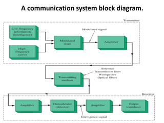
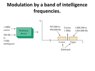
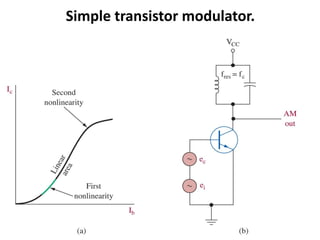
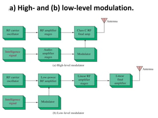
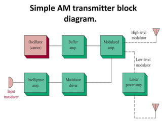
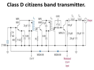
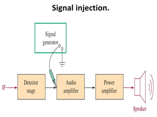
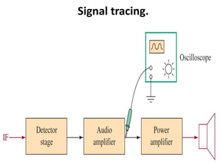
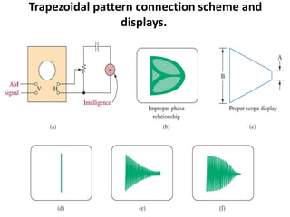
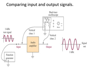
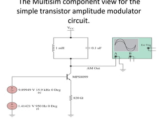
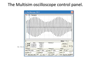
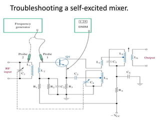
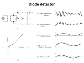
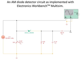
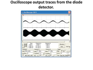
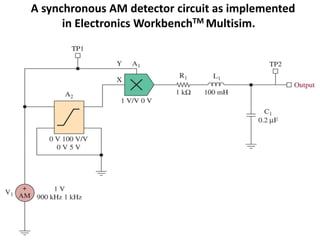
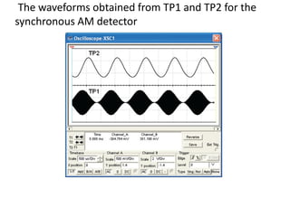
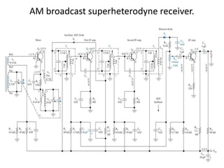
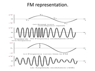
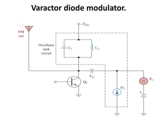
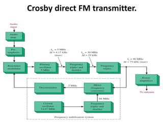
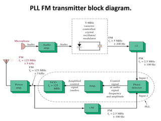
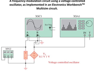
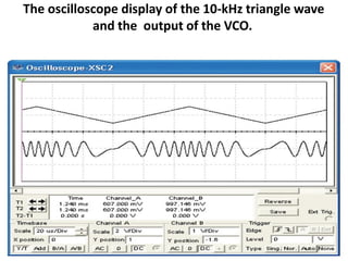
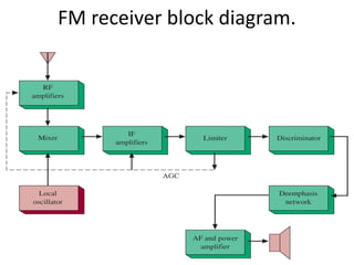
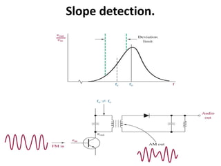
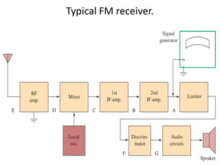
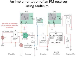
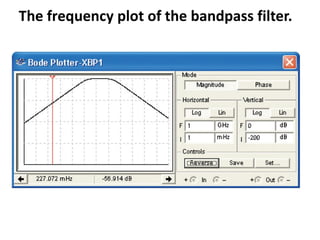
This document discusses various electronic communication systems including amplitude modulation (AM) and frequency modulation (FM) transmitters and receivers. It provides block diagrams and circuit implementations of basic AM transmitters using a transistor modulator. It also covers AM receivers using diode and synchronous detectors. For FM it discusses varactor diode modulation, direct and phase locked loop transmitters as well as FM receiver designs using slope detection. Circuit simulations and output waveforms are presented for several of the communication system examples.


![[HUBDAY] UDECAM, Quels nouveaux challenges pour les agences médias ?](https://cdn.slidesharecdn.com/ss_thumbnails/udecam-nouveauxchallenges-150420033510-conversion-gate02-thumbnail.jpg?width=640&height=640&fit=bounds)