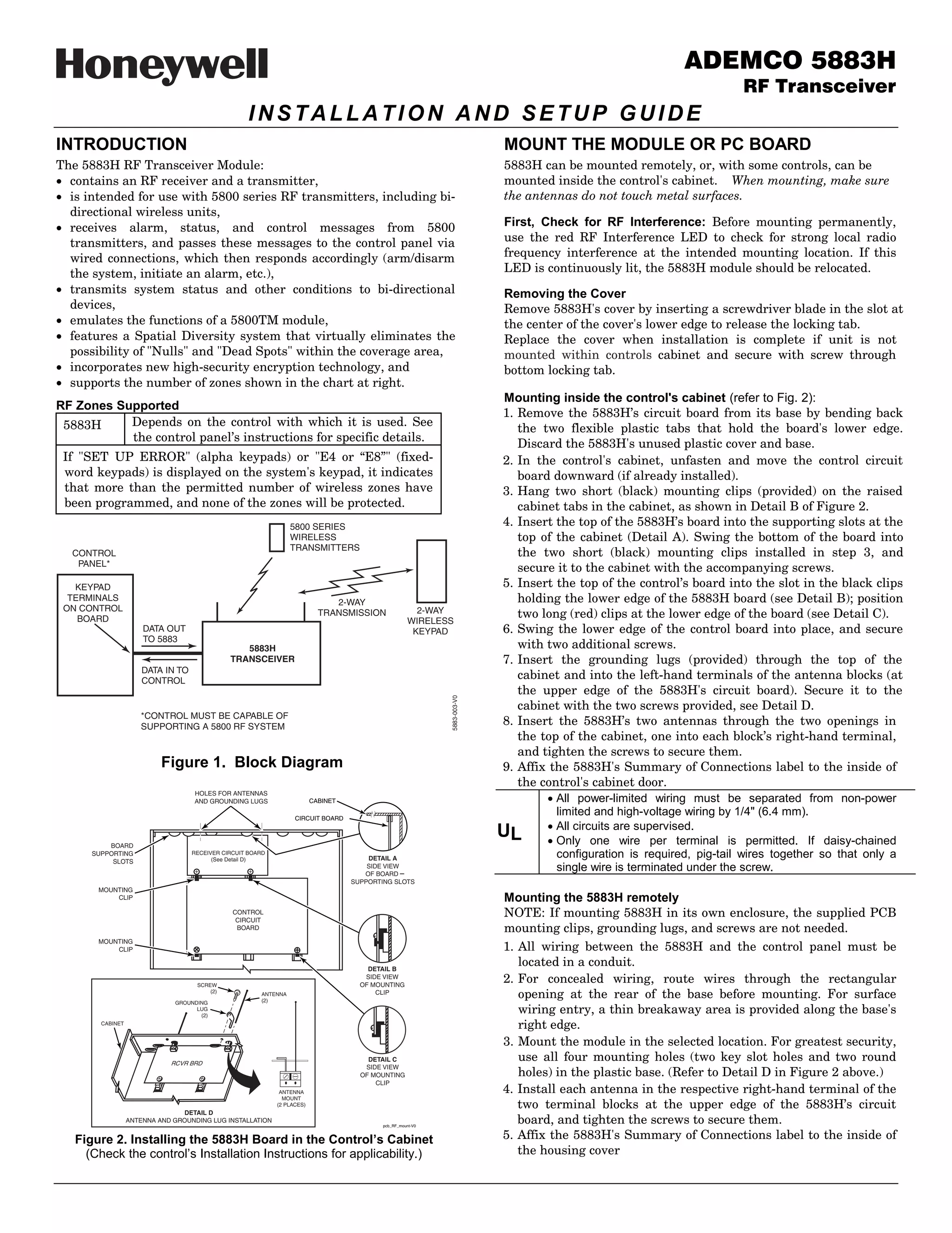
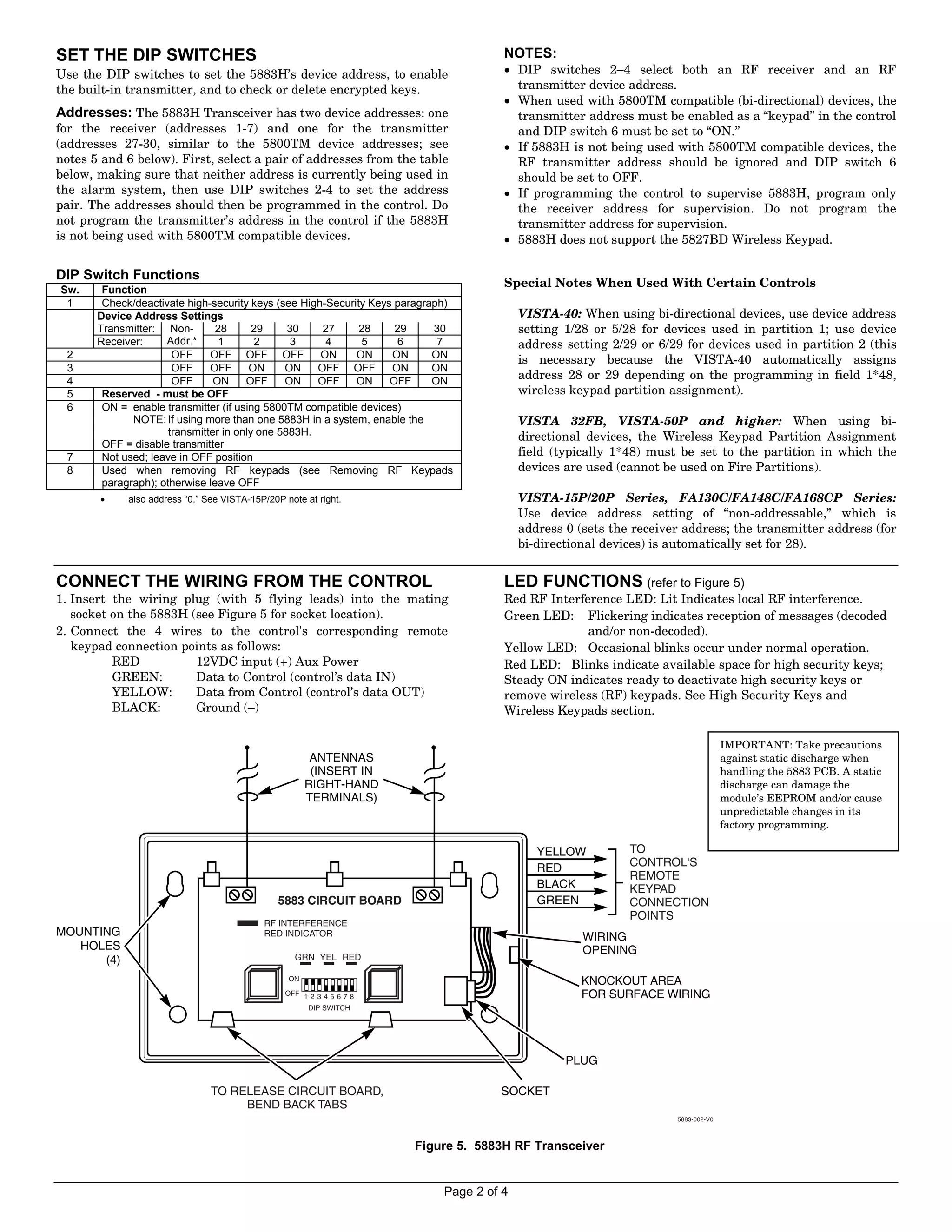
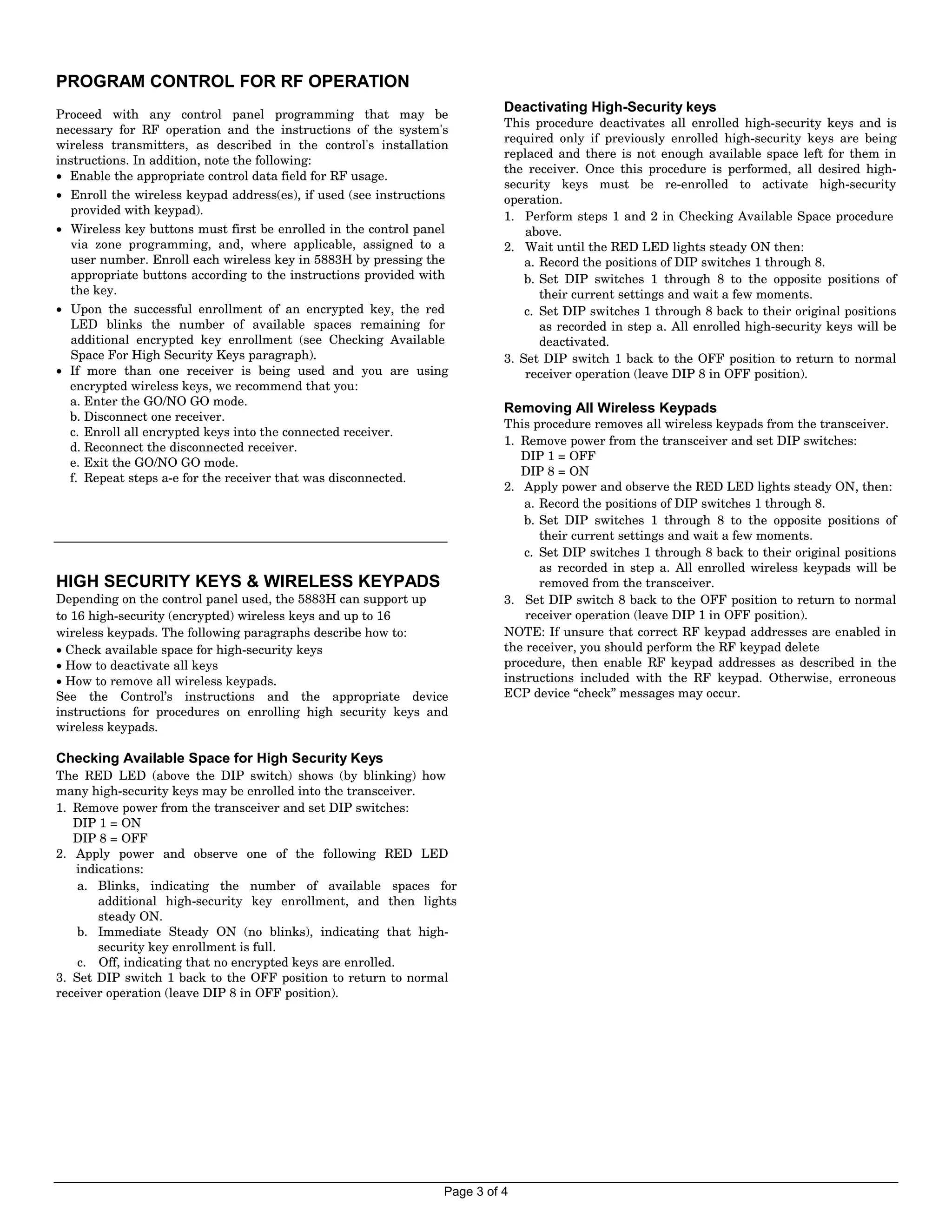
SlideShare a Scribd company logo
ADEMCO 5883H
                                                                                                                                                                          RF Transceiver
                                                     INSTALLATION AND SETUP GUIDE
INTRODUCTION                                                                                                                 MOUNT THE MODULE OR PC BOARD
The 5883H RF Transceiver Module:                                                                                             5883H can be mounted remotely, or, with some controls, can be
! contains an RF receiver and a transmitter,                                                                                 mounted inside the control's cabinet. When mounting, make sure
! is intended for use with 5800 series RF transmitters, including bi-                                                        the antennas do not touch metal surfaces.
  directional wireless units,
! receives alarm, status, and control messages from 5800                                                                     First, Check for RF Interference: Before mounting permanently,
  transmitters, and passes these messages to the control panel via                                                           use the red RF Interference LED to check for strong local radio
  wired connections, which then responds accordingly (arm/disarm                                                             frequency interference at the intended mounting location. If this
  the system, initiate an alarm, etc.),                                                                                      LED is continuously lit, the 5883H module should be relocated.
! transmits system status and other conditions to bi-directional                                                             Removing the Cover
  devices,                                                                                                                   Remove 5883H's cover by inserting a screwdriver blade in the slot at
! emulates the functions of a 5800TM module,                                                                                 the center of the cover's lower edge to release the locking tab.
! features a Spatial Diversity system that virtually eliminates the                                                          Replace the cover when installation is complete if unit is not
  possibility of "Nulls" and "Dead Spots" within the coverage area,                                                          mounted within controls cabinet and secure with screw through
! incorporates new high-security encryption technology, and                                                                  bottom locking tab.
! supports the number of zones shown in the chart at right.
                                                                                                                             Mounting inside the control's cabinet (refer to Fig. 2):
RF Zones Supported
                                                                                                                             1. Remove the 5883Hโ€™s circuit board from its base by bending back
 5883H     Depends on the control with which it is used. See
                                                                                                                                the two flexible plastic tabs that hold the board's lower edge.
           the control panelโ€™s instructions for specific details.
                                                                                                                                Discard the 5883H's unused plastic cover and base.
 If "SET UP ERROR" (alpha keypads) or "E4 or โ€œE8โ€" (fixed-                                                                   2. In the control's cabinet, unfasten and move the control circuit
 word keypads) is displayed on the system's keypad, it indicates                                                                board downward (if already installed).
 that more than the permitted number of wireless zones have                                                                  3. Hang two short (black) mounting clips (provided) on the raised
 been programmed, and none of the zones will be protected.                                                                      cabinet tabs in the cabinet, as shown in Detail B of Figure 2.
                                                                    5800 SERIES                                              4. Insert the top of the 5883Hโ€™s board into the supporting slots at the
                                                                    WIRELESS                                                    top of the cabinet (Detail A). Swing the bottom of the board into
                                                                    TRANSMITTERS
  CONTROL                                                                                                                       the two short (black) mounting clips installed in step 3, and
   PANEL*
                                                                                                                                secure it to the cabinet with the accompanying screws.
   KEYPAD                                                                                                                    5. Insert the top of the controlโ€™s board into the slot in the black clips
  TERMINALS                                                                     2-WAY                                           holding the lower edge of the 5883H board (see Detail B); position
 ON CONTROL                                                                                               2-WAY
    BOARD
                                                                             TRANSMISSION                                       two long (red) clips at the lower edge of the board (see Detail C).
                                                                                                        WIRELESS
                      DATA OUT                                                                           KEYPAD              6. Swing the lower edge of the control board into place, and secure
                      TO 5883
                                                   5883H                                                                        with two additional screws.
                                                TRANSCEIVER                                                                  7. Insert the grounding lugs (provided) through the top of the
                      DATA IN TO
                      CONTROL
                                                                                                                                cabinet and into the left-hand terminals of the antenna blocks (at
                                                                                                                                the upper edge of the 5883H's circuit board). Secure it to the
                                                                                                               5883-003-V0


                                                                                                                                cabinet with the two screws provided, see Detail D.
                     *CONTROL MUST BE CAPABLE OF
                     SUPPORTING A 5800 RF SYSTEM
                                                                                                                             8. Insert the 5883Hโ€™s two antennas through the two openings in
                                                                                                                                the top of the cabinet, one into each blockโ€™s right-hand terminal,
                                                                                                                                and tighten the screws to secure them.
                              Figure 1. Block Diagram                                                                        9. Affix the 5883H's Summary of Connections label to the inside of
                                                                                                                                the control's cabinet door.
                                     HOLES FOR ANTENNAS
                                     AND GROUNDING LUGS                    CABINET                                                   ! All power-limited wiring must be separated from non-power
                                                                    CIRCUIT BOARD
                                                                                                                                       limited and high-voltage wiring by 1/4" (6.4 mm).
                                                                                                                                     ! All circuits are supervised.
                                                                                                                             UL      ! Only one wire per terminal is permitted. If daisy-chained
          BOARD
      SUPPORTING                     RECEIVER CIRCUIT BOARD
                                           (See Detail D)                                DETAIL A                                      configuration is required, pig-tail wires together so that only a
           SLOTS
                                      +               +
                                                                                         SIDE VIEW
                                                                                        OF BOARD
                                                                                                                                       single wire is terminated under the screw.
                                                                                     SUPPORTING SLOTS
       MOUNTING
           CLIP                                                                                                              Mounting the 5883H remotely
                                                 CONTROL
                                                  CIRCUIT
                                                                                                                             NOTE: If mounting 5883H in its own enclosure, the supplied PCB
                                                  BOARD                                                                      mounting clips, grounding lugs, and screws are not needed.
       MOUNTING
           CLIP                                                                                                              1. All wiring between the 5883H and the control panel must be
                                                                                         DETAIL B
                                                                                                                                located in a conduit.
                                      SCREW
                                                                                        SIDE VIEW
                                                                                       OF MOUNTING
                                                                                                                             2. For concealed wiring, route wires through the rectangular
                                          (2)
                                                          ANTENNA
                                                          (2)
                                                                                           CLIP
                                                                                                                                opening at the rear of the base before mounting. For surface
                                GROUNDING
                                      LUG
                                       (2)
                                                                                                                                wiring entry, a thin breakaway area is provided along the base's
        CABINET
                                                                                                                                right edge.
                                                                                                                             3. Mount the module in the selected location. For greatest security,
                               RCVR BRD
                                                                                         DETAIL C                               use all four mounting holes (two key slot holes and two round
                                                                                        SIDE VIEW
                          +               +                                            OF MOUNTING                              holes) in the plastic base. (Refer to Detail D in Figure 2 above.)
                                                                                           CLIP
                                                               ANTENNA                                                       4. Install each antenna in the respective right-hand terminal of the
                                                                MOUNT
                                                              (2 PLACES)                                                        two terminal blocks at the upper edge of the 5883Hโ€™s circuit
                                DETAIL D
                  ANTENNA AND GROUNDING LUG INSTALLATION
                                                                                             pcb_RF_mount-V0
                                                                                                                                board, and tighten the screws to secure them.
   Figure 2. Installing the 5883H Board in the Controlโ€™s Cabinet                                                             5. Affix the 5883H's Summary of Connections label to the inside of
     (Check the controlโ€™s Installation Instructions for applicability.)                                                         the housing cover
SET THE DIP SWITCHES                                                                  NOTES:
Use the DIP switches to set the 5883Hโ€™s device address, to enable                     ! DIP switches 2โ€“4 select both an RF receiver and an RF
the built-in transmitter, and to check or delete encrypted keys.                        transmitter device address.
                                                                                      ! When used with 5800TM compatible (bi-directional) devices, the
Addresses: The 5883H Transceiver has two device addresses: one                          transmitter address must be enabled as a โ€œkeypadโ€ in the control
for the receiver (addresses 1-7) and one for the transmitter                            and DIP switch 6 must be set to โ€œON.โ€
(addresses 27-30, similar to the 5800TM device addresses; see                         ! If 5883H is not being used with 5800TM compatible devices, the
notes 5 and 6 below). First, select a pair of addresses from the table                  RF transmitter address should be ignored and DIP switch 6
below, making sure that neither address is currently being used in                      should be set to OFF.
the alarm system, then use DIP switches 2-4 to set the address                        ! If programming the control to supervise 5883H, program only
pair. The addresses should then be programmed in the control. Do                        the receiver address for supervision. Do not program the
not program the transmitterโ€™s address in the control if the 5883H                       transmitter address for supervision.
is not being used with 5800TM compatible devices.                                     ! 5883H does not support the 5827BD Wireless Keypad.

DIP Switch Functions
                                                                                      Special Notes When Used With Certain Controls
Sw.     Function
 1      Check/deactivate high-security keys (see High-Security Keys paragraph)
       Device Address Settings                                                            VISTA-40: When using bi-directional devices, use device address
       Transmitter: Non-        28       29     30    27     28     29     30             setting 1/28 or 5/28 for devices used in partition 1; use device
       Receiver:     Addr.*      1       2      3     4      5      6       7             address setting 2/29 or 6/29 for devices used in partition 2 (this
 2                     OFF     OFF OFF OFF           ON     ON     ON      ON             is necessary because the VISTA-40 automatically assigns
 3                     OFF     OFF      ON     ON    OFF OFF       ON      ON
 4                     OFF      ON     OFF     ON    OFF    ON     OFF     ON
                                                                                          address 28 or 29 depending on the programming in field 1*48,
 5      Reserved - must be OFF                                                            wireless keypad partition assignment).
 6      ON = enable transmitter (if using 5800TM compatible devices)
              NOTE: If using more than one 5883H in a system, enable the                  VISTA 32FB, VISTA-50P and higher: When using bi-
                      transmitter in only one 5883H.                                      directional devices, the Wireless Keypad Partition Assignment
        OFF = disable transmitter
 7      Not used; leave in OFF position                                                   field (typically 1*48) must be set to the partition in which the
 8      Used when removing RF keypads (see Removing RF Keypads                            devices are used (cannot be used on Fire Partitions).
        paragraph); otherwise leave OFF
       !     also address โ€œ0.โ€ See VISTA-15P/20P note at right.                           VISTA-15P/20P Series, FA130C/FA148C/FA168CP Series:
                                                                                          Use device address setting of โ€œnon-addressable,โ€ which is
                                                                                          address 0 (sets the receiver address; the transmitter address (for
                                                                                          bi-directional devices) is automatically set for 28).


CONNECT THE WIRING FROM THE CONTROL                                                   LED FUNCTIONS (refer to Figure 5)
1. Insert the wiring plug (with 5 flying leads) into the mating                       Red RF Interference LED: Lit Indicates local RF interference.
   socket on the 5883H (see Figure 5 for socket location).                            Green LED: Flickering indicates reception of messages (decoded
2. Connect the 4 wires to the control's corresponding remote                                        and/or non-decoded).
   keypad connection points as follows:                                               Yellow LED: Occasional blinks occur under normal operation.
          RED           12VDC input (+) Aux Power                                     Red LED: Blinks indicate available space for high security keys;
          GREEN:        Data to Control (controlโ€™s data IN)                           Steady ON indicates ready to deactivate high security keys or
          YELLOW:       Data from Control (controlโ€™s data OUT)                        remove wireless (RF) keypads. See High Security Keys and
          BLACK:        Ground (โ€“)                                                    Wireless Keypads section.

                                                                                                                                   IMPORTANT: Take precautions
                                                        ANTENNAS                                                                   against static discharge when
                                                        (INSERT IN                                                                 handling the 5883 PCB. A static
                                                       RIGHT-HAND                                                                  discharge can damage the
                                                       TERMINALS)                                                                  moduleโ€™s EEPROM and/or cause
                                                                                                                                   unpredictable changes in its
                                                                                                                                   factory programming.

                                                                                             YELLOW          TO
                                                                                             RED             CONTROL'S
                                                                                                             REMOTE
                                                                                             BLACK           KEYPAD
                                                5883 CIRCUIT BOARD                           GREEN           CONNECTION
                                                                                                             POINTS
                                            RF INTERFERENCE
MOUNTING                                    RED INDICATOR                                            WIRING
   HOLES                                                                                             OPENING
      (4)                                           GRN YEL RED

                                                  ON                                                 KNOCKOUT AREA
                                                 OFF 1 2 3 4 5 6 7 8                                 FOR SURFACE WIRING
                                                       DIP SWITCH


                                                                                                  PLUG

                                TO RELEASE CIRCUIT BOARD,                            SOCKET
                                     BEND BACK TABS
                                                                                                                     5883-002-V0


                                                                       Figure 5. 5883H RF Transceiver


                                                                            Page 2 of 4
PROGRAM CONTROL FOR RF OPERATION
Proceed with any control panel programming that may be
                                                                            Deactivating High-Security keys
                                                                            This procedure deactivates all enrolled high-security keys and is
necessary for RF operation and the instructions of the system's
                                                                            required only if previously enrolled high-security keys are being
wireless transmitters, as described in the control's installation
                                                                            replaced and there is not enough available space left for them in
instructions. In addition, note the following:
                                                                            the receiver. Once this procedure is performed, all desired high-
! Enable the appropriate control data field for RF usage.
                                                                            security keys must be re-enrolled to activate high-security
! Enroll the wireless keypad address(es), if used (see instructions         operation.
  provided with keypad).                                                    1. Perform steps 1 and 2 in Checking Available Space procedure
! Wireless key buttons must first be enrolled in the control panel              above.
  via zone programming, and, where applicable, assigned to a                2. Wait until the RED LED lights steady ON then:
  user number. Enroll each wireless key in 5883H by pressing the                a. Record the positions of DIP switches 1 through 8.
  appropriate buttons according to the instructions provided with               b. Set DIP switches 1 through 8 to the opposite positions of
  the key.                                                                         their current settings and wait a few moments.
! Upon the successful enrollment of an encrypted key, the red                   c. Set DIP switches 1 through 8 back to their original positions
  LED blinks the number of available spaces remaining for                          as recorded in step a. All enrolled high-security keys will be
  additional encrypted key enrollment (see Checking Available                      deactivated.
  Space For High Security Keys paragraph).                                  3. Set DIP switch 1 back to the OFF position to return to normal
! If more than one receiver is being used and you are using                     receiver operation (leave DIP 8 in OFF position).
  encrypted wireless keys, we recommend that you:
  a. Enter the GO/NO GO mode.
                                                                            Removing All Wireless Keypads
  b. Disconnect one receiver.
                                                                            This procedure removes all wireless keypads from the transceiver.
  c. Enroll all encrypted keys into the connected receiver.
                                                                            1. Remove power from the transceiver and set DIP switches:
  d. Reconnect the disconnected receiver.
                                                                               DIP 1 = OFF
  e. Exit the GO/NO GO mode.
                                                                               DIP 8 = ON
  f. Repeat steps a-e for the receiver that was disconnected.
                                                                            2. Apply power and observe the RED LED lights steady ON, then:
                                                                                a. Record the positions of DIP switches 1 through 8.
                                                                                b. Set DIP switches 1 through 8 to the opposite positions of
                                                                                   their current settings and wait a few moments.
                                                                                c. Set DIP switches 1 through 8 back to their original positions
                                                                                   as recorded in step a. All enrolled wireless keypads will be
HIGH SECURITY KEYS & WIRELESS KEYPADS                                              removed from the transceiver.
Depending on the control panel used, the 5883H can support up               3. Set DIP switch 8 back to the OFF position to return to normal
to 16 high-security (encrypted) wireless keys and up to 16                      receiver operation (leave DIP 1 in OFF position).
wireless keypads. The following paragraphs describe how to:                 NOTE: If unsure that correct RF keypad addresses are enabled in
! Check available space for high-security keys                              the receiver, you should perform the RF keypad delete
! How to deactivate all keys                                                procedure, then enable RF keypad addresses as described in the
! How to remove all wireless keypads.                                       instructions included with the RF keypad. Otherwise, erroneous
See the Controlโ€™s instructions and the appropriate device                   ECP device โ€œcheckโ€ messages may occur.
instructions for procedures on enrolling high security keys and
wireless keypads.

Checking Available Space for High Security Keys
The RED LED (above the DIP switch) shows (by blinking) how
many high-security keys may be enrolled into the transceiver.
1. Remove power from the transceiver and set DIP switches:
   DIP 1 = ON
   DIP 8 = OFF
2. Apply power and observe one of the following RED LED
   indications:
    a. Blinks, indicating the number of available spaces for
       additional high-security key enrollment, and then lights
       steady ON.
    b. Immediate Steady ON (no blinks), indicating that high-
       security key enrollment is full.
    c. Off, indicating that no encrypted keys are enrolled.
3. Set DIP switch 1 back to the OFF position to return to normal
receiver operation (leave DIP 8 in OFF position).


                                                                  Page 3 of 4
SPECIFICATIONS                                                                  TO THE INSTALLER
Dimensions:                                                                     Regular maintenance and inspection (at least annually) by
5883H: 7-3/8" W x 4-3/8" (10-7/8โ€ w/antenna) H x 1-7/16" D                      the installer and frequent testing by the user are vital to
       188mm W x 112mm H (277mm w/antenna) x 37mm D                             continuous satisfactory operation of any alarm system. The
                                                                                installer should assume the responsibility of developing and
Input Voltage: 12VDC (from controlโ€™s remote keypad terminals)                   offering a regular maintenance program to the user, as well
Current: 80mA typical                                                           as acquainting the user with the proper operation and
Range: 200ft (60m) nominal indoors from wireless devices (actual                limitations of the alarm system and its component parts.
           range is determined with the control in TEST mode)                   Recommendations must be included for a specific program
Receiver Sensitivity & Noise Rejection:                                         of frequent testing (at least weekly) to insure the system's
Receiver sensitivity and noise rejection are dynamically adjusted to            operation at all times.
match ambient conditions. Unacceptably high noise levels or low
signal levels are indicated at the control panel. For test procedure,
refer to the Installation & Setup Guide for the control panel with
which this device is used.


  FEDERAL COMMUNICATIONS COMMISSION STATEMENTS
  The user shall not make any changes or modifications to the equipment unless authorized by the Installation Instructions or User's
  Manual. Unauthorized changes or modifications could void the user's authority to operate the equipment.

  CLASS B DIGITAL DEVICE STATEMENT
  This equipment has been tested to FCC requirements and has been found acceptable for use. The FCC requires the following statement for
  your information:
  This equipment generates and uses radio frequency energy and if not installed and used properly, that is, in strict accordance with the
  manufacturer's instructions, may cause interference to radio and television reception. It has been type tested and found to comply with the
  limits for a Class B computing device in accordance with the specifications in Part 15 of FCC Rules, which are designed to provide
  reasonable protection against such interference in a residential installation. However, there is no guarantee that interference will not occur
  in a particular installation. If this equipment does cause interference to radio or television reception, which can be determined by turning
  the equipment off and on, the user is encouraged to try to correct the interference by one or more of the following measures:
  โ€ข If using an indoor antenna, have a quality outdoor antenna installed.
  โ€ข Reorient the receiving antenna until interference is reduced or eliminated.
  โ€ข Move the radio or television receiver away from the receiver/control.
  โ€ข Move the antenna leads away from any wire runs to the receiver/control.
  โ€ข Plug the receiver/control into a different outlet so that it and the radio or television receiver are on different branch circuits.
  โ€ข Consult the dealer or an experienced radio/TV technician for help.

  INDUSTRY CANADA (IC) STATEMENTS
  This device complies with Part 15 of the FCC Rules and RSS210 of Industry Canada. Operation is subject to the following two conditions:
  (1) This device may not cause harmful interference, and (2) This device must accept any interference received, including interference that
  may cause undesired operation.
  Cet appareil est conforme ร  la partie 15 des rรจgles de la FCC & de RSS 210 des Industries Canada. Son fonctionnement est soumis aux
  conditions suivantes: (1) Cet appareil ne doit pas causer d' interferences nuisibles. (2) Cet appareil doit accepter toute interference reรงue y
  compris les interferences causant une reception indรฉsirable.
  This Class B digital apparatus complies with Canadian ICES-003.
  Cet appareil numรฉrique de la classe B est conforme ร  la norme NMB-003 du Canada.


         FOR LIMITATIONS OF THE ENTIRE ALARM SYSTEM, REFER TO THE INSTALLATION INSTRUCTIONS FOR THE
         CONTROL WITH WHICH THIS DEVICE IS USED.


                                                 For the latest warranty information, please go to:
                                          http://www.security.honeywell.com/hsc/resources/wa/index.html


                             2 Corporate Center Drive, Suite 100
                              P.O. Box 9040, Melville, NY 11747
                              Copyright ยฉ 2009 Honeywell International Inc.                                                    รŠK3791V4oล 
                                       www.honeywell.com/security                                                             K3791V4     04/10 Rev. A

More Related Content

What's hot

12-working details-ceiling-by Prof Dr. Ehab Ezzat 2019
12-working details-ceiling-by Prof Dr. Ehab Ezzat 201912-working details-ceiling-by Prof Dr. Ehab Ezzat 2019
12-working details-ceiling-by Prof Dr. Ehab Ezzat 2019
Faculty of fine arts -Cairo. Egypt.
ย 
Pullbox sizing
Pullbox sizingPullbox sizing
Pullbox sizing
michaeljmack
ย 
2018 kitchen cabinet technical manual Oppein Home
2018 kitchen cabinet technical manual Oppein Home2018 kitchen cabinet technical manual Oppein Home
2018 kitchen cabinet technical manual Oppein Home
miyahuang4
ย 
Unit 6
Unit 6Unit 6
Unit 6
SHREYAS321
ย 
Containers-modular construction technology
Containers-modular construction technologyContainers-modular construction technology
Containers-modular construction technology
Anjith Augustine
ย 
[Asian Architecture] Vernacular as an Essence in Contemporary Design : A Stud...
[Asian Architecture] Vernacular as an Essence in Contemporary Design : A Stud...[Asian Architecture] Vernacular as an Essence in Contemporary Design : A Stud...
[Asian Architecture] Vernacular as an Essence in Contemporary Design : A Stud...
Patricia Kong
ย 
Timber window
Timber windowTimber window
Timber window
Abhay Aitwade
ย 
Shobe trusses
Shobe trussesShobe trusses
Shobe trusses
Shobbbe
ย 
05 ec2 ws_arrieta_detailing
05 ec2 ws_arrieta_detailing05 ec2 ws_arrieta_detailing
05 ec2 ws_arrieta_detailingluantvconst
ย 
7 english 2 2.5 brick thick bond
7 english 2 2.5 brick thick bond7 english 2 2.5 brick thick bond
7 english 2 2.5 brick thick bondVartika khandelwal
ย 
Soldaduras especiales
Soldaduras especialesSoldaduras especiales
Soldaduras especiales
wilmerramirez40
ย 
Alfabeto di arduino - lezione 4
Alfabeto di arduino - lezione 4Alfabeto di arduino - lezione 4
Alfabeto di arduino - lezione 4
Michele Maffucci
ย 
Industrial buildings
Industrial buildingsIndustrial buildings
Industrial buildings
AkshataFarakate
ย 
Roxtec MCT - Cable Entry Solutions for Process Industries
Roxtec MCT - Cable Entry Solutions for Process IndustriesRoxtec MCT - Cable Entry Solutions for Process Industries
Roxtec MCT - Cable Entry Solutions for Process Industries
Allen Gibson
ย 
Precast concrete construction
Precast concrete constructionPrecast concrete construction
Precast concrete construction
Ramin Vaghei
ย 
Arches - Form Active Structure System
Arches - Form Active Structure SystemArches - Form Active Structure System
Arches - Form Active Structure System
Archistudent Portal
ย 
Geodesic Dome and Ribbed Dome
Geodesic Dome and Ribbed DomeGeodesic Dome and Ribbed Dome
Geodesic Dome and Ribbed Dome
Geetika Singla
ย 
Space structure
Space structureSpace structure
Space structure
PAYALKARAVADRA
ย 
Raised Floor Research.pptx
Raised Floor Research.pptxRaised Floor Research.pptx
Raised Floor Research.pptx
ssuser8634982
ย 
Glass Murals
Glass MuralsGlass Murals
Glass Murals
Chandan K B
ย 

What's hot (20)

12-working details-ceiling-by Prof Dr. Ehab Ezzat 2019
12-working details-ceiling-by Prof Dr. Ehab Ezzat 201912-working details-ceiling-by Prof Dr. Ehab Ezzat 2019
12-working details-ceiling-by Prof Dr. Ehab Ezzat 2019
ย 
Pullbox sizing
Pullbox sizingPullbox sizing
Pullbox sizing
ย 
2018 kitchen cabinet technical manual Oppein Home
2018 kitchen cabinet technical manual Oppein Home2018 kitchen cabinet technical manual Oppein Home
2018 kitchen cabinet technical manual Oppein Home
ย 
Unit 6
Unit 6Unit 6
Unit 6
ย 
Containers-modular construction technology
Containers-modular construction technologyContainers-modular construction technology
Containers-modular construction technology
ย 
[Asian Architecture] Vernacular as an Essence in Contemporary Design : A Stud...
[Asian Architecture] Vernacular as an Essence in Contemporary Design : A Stud...[Asian Architecture] Vernacular as an Essence in Contemporary Design : A Stud...
[Asian Architecture] Vernacular as an Essence in Contemporary Design : A Stud...
ย 
Timber window
Timber windowTimber window
Timber window
ย 
Shobe trusses
Shobe trussesShobe trusses
Shobe trusses
ย 
05 ec2 ws_arrieta_detailing
05 ec2 ws_arrieta_detailing05 ec2 ws_arrieta_detailing
05 ec2 ws_arrieta_detailing
ย 
7 english 2 2.5 brick thick bond
7 english 2 2.5 brick thick bond7 english 2 2.5 brick thick bond
7 english 2 2.5 brick thick bond
ย 
Soldaduras especiales
Soldaduras especialesSoldaduras especiales
Soldaduras especiales
ย 
Alfabeto di arduino - lezione 4
Alfabeto di arduino - lezione 4Alfabeto di arduino - lezione 4
Alfabeto di arduino - lezione 4
ย 
Industrial buildings
Industrial buildingsIndustrial buildings
Industrial buildings
ย 
Roxtec MCT - Cable Entry Solutions for Process Industries
Roxtec MCT - Cable Entry Solutions for Process IndustriesRoxtec MCT - Cable Entry Solutions for Process Industries
Roxtec MCT - Cable Entry Solutions for Process Industries
ย 
Precast concrete construction
Precast concrete constructionPrecast concrete construction
Precast concrete construction
ย 
Arches - Form Active Structure System
Arches - Form Active Structure SystemArches - Form Active Structure System
Arches - Form Active Structure System
ย 
Geodesic Dome and Ribbed Dome
Geodesic Dome and Ribbed DomeGeodesic Dome and Ribbed Dome
Geodesic Dome and Ribbed Dome
ย 
Space structure
Space structureSpace structure
Space structure
ย 
Raised Floor Research.pptx
Raised Floor Research.pptxRaised Floor Research.pptx
Raised Floor Research.pptx
ย 
Glass Murals
Glass MuralsGlass Murals
Glass Murals
ย 

Similar to Honeywell 5883h-install-guide

Honeywell 5814-install-guide
Honeywell 5814-install-guideHoneywell 5814-install-guide
Honeywell 5814-install-guideAlarm Grid
ย 
Honeywell 5828-and-honeywell-5828v-install-guide
Honeywell 5828-and-honeywell-5828v-install-guideHoneywell 5828-and-honeywell-5828v-install-guide
Honeywell 5828-and-honeywell-5828v-install-guideAlarm Grid
ย 
Honeywell 5818mnl-install-guide
Honeywell 5818mnl-install-guideHoneywell 5818mnl-install-guide
Honeywell 5818mnl-install-guideAlarm Grid
ย 
Honeywell 5820l-install-guide
Honeywell 5820l-install-guideHoneywell 5820l-install-guide
Honeywell 5820l-install-guideAlarm Grid
ย 
Honeywell 5869-install-guide
Honeywell 5869-install-guideHoneywell 5869-install-guide
Honeywell 5869-install-guideAlarm Grid
ย 
Honeywell 5821-install-guide
Honeywell 5821-install-guideHoneywell 5821-install-guide
Honeywell 5821-install-guideAlarm Grid
ย 
Honeywell 5869-data-sheet
Honeywell 5869-data-sheetHoneywell 5869-data-sheet
Honeywell 5869-data-sheetAlarm Grid
ย 
Honeywell 5819whs-5819brs-install-guide
Honeywell 5819whs-5819brs-install-guideHoneywell 5819whs-5819brs-install-guide
Honeywell 5819whs-5819brs-install-guideAlarm Grid
ย 
Honeywell 5843-install-guide
Honeywell 5843-install-guideHoneywell 5843-install-guide
Honeywell 5843-install-guideAlarm Grid
ย 
Honeywell 5802mn2-install-guide
Honeywell 5802mn2-install-guideHoneywell 5802mn2-install-guide
Honeywell 5802mn2-install-guideAlarm Grid
ย 
Honeywell 5839-install-guide
Honeywell 5839-install-guideHoneywell 5839-install-guide
Honeywell 5839-install-guideAlarm Grid
ย 
Honeywell 6150-honeywell-6160-install-guide
Honeywell 6150-honeywell-6160-install-guideHoneywell 6150-honeywell-6160-install-guide
Honeywell 6150-honeywell-6160-install-guideAlarm Grid
ย 
Honeywell 5878-install-guide
Honeywell 5878-install-guideHoneywell 5878-install-guide
Honeywell 5878-install-guideAlarm Grid
ย 
Honeywell 5878-user-guide
Honeywell 5878-user-guideHoneywell 5878-user-guide
Honeywell 5878-user-guideAlarm Grid
ย 
Honeywell 5802mn-install-guide
Honeywell 5802mn-install-guideHoneywell 5802mn-install-guide
Honeywell 5802mn-install-guideAlarm Grid
ย 
Honeywell 6164 us-install-guide
Honeywell 6164 us-install-guideHoneywell 6164 us-install-guide
Honeywell 6164 us-install-guideAlarm Grid
ย 
Honeywell 6151-install-guide
Honeywell 6151-install-guideHoneywell 6151-install-guide
Honeywell 6151-install-guideAlarm Grid
ย 
Honeywell 5817cb-data-sheet
Honeywell 5817cb-data-sheetHoneywell 5817cb-data-sheet
Honeywell 5817cb-data-sheetAlarm Grid
ย 

Similar to Honeywell 5883h-install-guide (20)

Honeywell 5814-install-guide
Honeywell 5814-install-guideHoneywell 5814-install-guide
Honeywell 5814-install-guide
ย 
Honeywell 5828-and-honeywell-5828v-install-guide
Honeywell 5828-and-honeywell-5828v-install-guideHoneywell 5828-and-honeywell-5828v-install-guide
Honeywell 5828-and-honeywell-5828v-install-guide
ย 
Honeywell 5818mnl-install-guide
Honeywell 5818mnl-install-guideHoneywell 5818mnl-install-guide
Honeywell 5818mnl-install-guide
ย 
Honeywell 5820l-install-guide
Honeywell 5820l-install-guideHoneywell 5820l-install-guide
Honeywell 5820l-install-guide
ย 
Honeywell 5869-install-guide
Honeywell 5869-install-guideHoneywell 5869-install-guide
Honeywell 5869-install-guide
ย 
Honeywell 5821-install-guide
Honeywell 5821-install-guideHoneywell 5821-install-guide
Honeywell 5821-install-guide
ย 
Honeywell 5869-data-sheet
Honeywell 5869-data-sheetHoneywell 5869-data-sheet
Honeywell 5869-data-sheet
ย 
Honeywell 5819whs-5819brs-install-guide
Honeywell 5819whs-5819brs-install-guideHoneywell 5819whs-5819brs-install-guide
Honeywell 5819whs-5819brs-install-guide
ย 
Honeywell 5843-install-guide
Honeywell 5843-install-guideHoneywell 5843-install-guide
Honeywell 5843-install-guide
ย 
Honeywell 5802mn2-install-guide
Honeywell 5802mn2-install-guideHoneywell 5802mn2-install-guide
Honeywell 5802mn2-install-guide
ย 
Honeywell 5839-install-guide
Honeywell 5839-install-guideHoneywell 5839-install-guide
Honeywell 5839-install-guide
ย 
Honeywell 6150-honeywell-6160-install-guide
Honeywell 6150-honeywell-6160-install-guideHoneywell 6150-honeywell-6160-install-guide
Honeywell 6150-honeywell-6160-install-guide
ย 
Exj 8 n
Exj 8 nExj 8 n
Exj 8 n
ย 
Honeywell 5878-install-guide
Honeywell 5878-install-guideHoneywell 5878-install-guide
Honeywell 5878-install-guide
ย 
Honeywell 5878-user-guide
Honeywell 5878-user-guideHoneywell 5878-user-guide
Honeywell 5878-user-guide
ย 
Honeywell 5802mn-install-guide
Honeywell 5802mn-install-guideHoneywell 5802mn-install-guide
Honeywell 5802mn-install-guide
ย 
Instructions iq2020-with-new-relay-board
Instructions iq2020-with-new-relay-boardInstructions iq2020-with-new-relay-board
Instructions iq2020-with-new-relay-board
ย 
Honeywell 6164 us-install-guide
Honeywell 6164 us-install-guideHoneywell 6164 us-install-guide
Honeywell 6164 us-install-guide
ย 
Honeywell 6151-install-guide
Honeywell 6151-install-guideHoneywell 6151-install-guide
Honeywell 6151-install-guide
ย 
Honeywell 5817cb-data-sheet
Honeywell 5817cb-data-sheetHoneywell 5817cb-data-sheet
Honeywell 5817cb-data-sheet
ย 

More from Alarm Grid

Vizia rf + system programming and control
Vizia rf + system programming and controlVizia rf + system programming and control
Vizia rf + system programming and controlAlarm Grid
ย 
Vizia rf + plug in spec sheet
Vizia rf + plug in spec sheetVizia rf + plug in spec sheet
Vizia rf + plug in spec sheetAlarm Grid
ย 
Leviton vrs15 1 lz installation manual and setup guide
Leviton vrs15 1 lz installation manual and setup guideLeviton vrs15 1 lz installation manual and setup guide
Leviton vrs15 1 lz installation manual and setup guideAlarm Grid
ย 
Leviton vrs05 1 lz installation manual and setup guide
Leviton vrs05 1 lz installation manual and setup guideLeviton vrs05 1 lz installation manual and setup guide
Leviton vrs05 1 lz installation manual and setup guideAlarm Grid
ย 
Leviton vrr15 1 lz product specification bulletin
Leviton vrr15 1 lz product specification bulletinLeviton vrr15 1 lz product specification bulletin
Leviton vrr15 1 lz product specification bulletinAlarm Grid
ย 
Leviton vrp15 z Installation Instructions and Setup Guide
Leviton vrp15 z Installation Instructions and Setup GuideLeviton vrp15 z Installation Instructions and Setup Guide
Leviton vrp15 z Installation Instructions and Setup GuideAlarm Grid
ย 
Leviton vrp03 z product manual and setup guide
Leviton vrp03 z product manual and setup guideLeviton vrp03 z product manual and setup guide
Leviton vrp03 z product manual and setup guideAlarm Grid
ย 
Leviton vri10 1 lz product manual and setup guide
Leviton vri10 1 lz product manual and setup guideLeviton vri10 1 lz product manual and setup guide
Leviton vri10 1 lz product manual and setup guideAlarm Grid
ย 
Leviton vri06 1 lz product manual and setup guide
Leviton vri06 1 lz product manual and setup guideLeviton vri06 1 lz product manual and setup guide
Leviton vri06 1 lz product manual and setup guideAlarm Grid
ย 
Leviton vrf01 1 lz product manual and setup guide
Leviton vrf01 1 lz product manual and setup guideLeviton vrf01 1 lz product manual and setup guide
Leviton vrf01 1 lz product manual and setup guideAlarm Grid
ย 
Leviton vre06 1 lz
Leviton vre06 1 lzLeviton vre06 1 lz
Leviton vre06 1 lzAlarm Grid
ย 
Leviton vrcz4 mr, vrcs4-mr, and vrc52-mr product specifications
Leviton vrcz4 mr, vrcs4-mr, and vrc52-mr product specificationsLeviton vrcz4 mr, vrcs4-mr, and vrc52-mr product specifications
Leviton vrcz4 mr, vrcs4-mr, and vrc52-mr product specificationsAlarm Grid
ย 
Leviton vrcz4 1 l, vrcs4-1l, vrcz1-1l, vrcs1-1l and vrmr1-osg product specifi...
Leviton vrcz4 1 l, vrcs4-1l, vrcz1-1l, vrcs1-1l and vrmr1-osg product specifi...Leviton vrcz4 1 l, vrcs4-1l, vrcz1-1l, vrcs1-1l and vrmr1-osg product specifi...
Leviton vrcz4 1 l, vrcs4-1l, vrcz1-1l, vrcs1-1l and vrmr1-osg product specifi...Alarm Grid
ย 
Leviton vrcz1 installation manual and setup guide
Leviton vrcz1 installation manual and setup guideLeviton vrcz1 installation manual and setup guide
Leviton vrcz1 installation manual and setup guideAlarm Grid
ย 
Leviton vrcs1 1 l
Leviton vrcs1 1 lLeviton vrcs1 1 l
Leviton vrcs1 1 lAlarm Grid
ย 
Leviton vp00 r 10z, vp00r-1lz, vp0sr-10z, vp0sr-1lz installation manual and s...
Leviton vp00 r 10z, vp00r-1lz, vp0sr-10z, vp0sr-1lz installation manual and s...Leviton vp00 r 10z, vp00r-1lz, vp0sr-10z, vp0sr-1lz installation manual and s...
Leviton vp00 r 10z, vp00r-1lz, vp0sr-10z, vp0sr-1lz installation manual and s...Alarm Grid
ย 
Leviton dimmers, switches and fan speed controllers
Leviton dimmers, switches and fan speed controllersLeviton dimmers, switches and fan speed controllers
Leviton dimmers, switches and fan speed controllersAlarm Grid
ย 
Fluorescent dimmer for hi lume or eco-10 ballasts
Fluorescent dimmer for hi lume or eco-10 ballastsFluorescent dimmer for hi lume or eco-10 ballasts
Fluorescent dimmer for hi lume or eco-10 ballastsAlarm Grid
ย 
Controlling z wave door locks with the vrc0 p
Controlling z wave door locks with the vrc0 pControlling z wave door locks with the vrc0 p
Controlling z wave door locks with the vrc0 pAlarm Grid
ย 
Vizia rf+ collection
Vizia rf+ collectionVizia rf+ collection
Vizia rf+ collectionAlarm Grid
ย 

More from Alarm Grid (20)

Vizia rf + system programming and control
Vizia rf + system programming and controlVizia rf + system programming and control
Vizia rf + system programming and control
ย 
Vizia rf + plug in spec sheet
Vizia rf + plug in spec sheetVizia rf + plug in spec sheet
Vizia rf + plug in spec sheet
ย 
Leviton vrs15 1 lz installation manual and setup guide
Leviton vrs15 1 lz installation manual and setup guideLeviton vrs15 1 lz installation manual and setup guide
Leviton vrs15 1 lz installation manual and setup guide
ย 
Leviton vrs05 1 lz installation manual and setup guide
Leviton vrs05 1 lz installation manual and setup guideLeviton vrs05 1 lz installation manual and setup guide
Leviton vrs05 1 lz installation manual and setup guide
ย 
Leviton vrr15 1 lz product specification bulletin
Leviton vrr15 1 lz product specification bulletinLeviton vrr15 1 lz product specification bulletin
Leviton vrr15 1 lz product specification bulletin
ย 
Leviton vrp15 z Installation Instructions and Setup Guide
Leviton vrp15 z Installation Instructions and Setup GuideLeviton vrp15 z Installation Instructions and Setup Guide
Leviton vrp15 z Installation Instructions and Setup Guide
ย 
Leviton vrp03 z product manual and setup guide
Leviton vrp03 z product manual and setup guideLeviton vrp03 z product manual and setup guide
Leviton vrp03 z product manual and setup guide
ย 
Leviton vri10 1 lz product manual and setup guide
Leviton vri10 1 lz product manual and setup guideLeviton vri10 1 lz product manual and setup guide
Leviton vri10 1 lz product manual and setup guide
ย 
Leviton vri06 1 lz product manual and setup guide
Leviton vri06 1 lz product manual and setup guideLeviton vri06 1 lz product manual and setup guide
Leviton vri06 1 lz product manual and setup guide
ย 
Leviton vrf01 1 lz product manual and setup guide
Leviton vrf01 1 lz product manual and setup guideLeviton vrf01 1 lz product manual and setup guide
Leviton vrf01 1 lz product manual and setup guide
ย 
Leviton vre06 1 lz
Leviton vre06 1 lzLeviton vre06 1 lz
Leviton vre06 1 lz
ย 
Leviton vrcz4 mr, vrcs4-mr, and vrc52-mr product specifications
Leviton vrcz4 mr, vrcs4-mr, and vrc52-mr product specificationsLeviton vrcz4 mr, vrcs4-mr, and vrc52-mr product specifications
Leviton vrcz4 mr, vrcs4-mr, and vrc52-mr product specifications
ย 
Leviton vrcz4 1 l, vrcs4-1l, vrcz1-1l, vrcs1-1l and vrmr1-osg product specifi...
Leviton vrcz4 1 l, vrcs4-1l, vrcz1-1l, vrcs1-1l and vrmr1-osg product specifi...Leviton vrcz4 1 l, vrcs4-1l, vrcz1-1l, vrcs1-1l and vrmr1-osg product specifi...
Leviton vrcz4 1 l, vrcs4-1l, vrcz1-1l, vrcs1-1l and vrmr1-osg product specifi...
ย 
Leviton vrcz1 installation manual and setup guide
Leviton vrcz1 installation manual and setup guideLeviton vrcz1 installation manual and setup guide
Leviton vrcz1 installation manual and setup guide
ย 
Leviton vrcs1 1 l
Leviton vrcs1 1 lLeviton vrcs1 1 l
Leviton vrcs1 1 l
ย 
Leviton vp00 r 10z, vp00r-1lz, vp0sr-10z, vp0sr-1lz installation manual and s...
Leviton vp00 r 10z, vp00r-1lz, vp0sr-10z, vp0sr-1lz installation manual and s...Leviton vp00 r 10z, vp00r-1lz, vp0sr-10z, vp0sr-1lz installation manual and s...
Leviton vp00 r 10z, vp00r-1lz, vp0sr-10z, vp0sr-1lz installation manual and s...
ย 
Leviton dimmers, switches and fan speed controllers
Leviton dimmers, switches and fan speed controllersLeviton dimmers, switches and fan speed controllers
Leviton dimmers, switches and fan speed controllers
ย 
Fluorescent dimmer for hi lume or eco-10 ballasts
Fluorescent dimmer for hi lume or eco-10 ballastsFluorescent dimmer for hi lume or eco-10 ballasts
Fluorescent dimmer for hi lume or eco-10 ballasts
ย 
Controlling z wave door locks with the vrc0 p
Controlling z wave door locks with the vrc0 pControlling z wave door locks with the vrc0 p
Controlling z wave door locks with the vrc0 p
ย 
Vizia rf+ collection
Vizia rf+ collectionVizia rf+ collection
Vizia rf+ collection
ย 

Recently uploaded

PriyoShop Celebration Pohela Falgun Mar 20, 2024
PriyoShop Celebration Pohela Falgun Mar 20, 2024PriyoShop Celebration Pohela Falgun Mar 20, 2024
PriyoShop Celebration Pohela Falgun Mar 20, 2024
PriyoShop.com LTD
ย 
Business Valuation Principles for Entrepreneurs
Business Valuation Principles for EntrepreneursBusiness Valuation Principles for Entrepreneurs
Business Valuation Principles for Entrepreneurs
Ben Wann
ย 
Role of Remote Sensing and Monitoring in Mining
Role of Remote Sensing and Monitoring in MiningRole of Remote Sensing and Monitoring in Mining
Role of Remote Sensing and Monitoring in Mining
Naaraayani Minerals Pvt.Ltd
ย 
Meas_Dylan_DMBS_PB1_2024-05XX_Revised.pdf
Meas_Dylan_DMBS_PB1_2024-05XX_Revised.pdfMeas_Dylan_DMBS_PB1_2024-05XX_Revised.pdf
Meas_Dylan_DMBS_PB1_2024-05XX_Revised.pdf
dylandmeas
ย 
What are the main advantages of using HR recruiter services.pdf
What are the main advantages of using HR recruiter services.pdfWhat are the main advantages of using HR recruiter services.pdf
What are the main advantages of using HR recruiter services.pdf
HumanResourceDimensi1
ย 
Memorandum Of Association Constitution of Company.ppt
Memorandum Of Association Constitution of Company.pptMemorandum Of Association Constitution of Company.ppt
Memorandum Of Association Constitution of Company.ppt
seri bangash
ย 
Unveiling the Secrets How Does Generative AI Work.pdf
Unveiling the Secrets How Does Generative AI Work.pdfUnveiling the Secrets How Does Generative AI Work.pdf
Unveiling the Secrets How Does Generative AI Work.pdf
Sam H
ย 
Digital Transformation in PLM - WHAT and HOW - for distribution.pdf
Digital Transformation in PLM - WHAT and HOW - for distribution.pdfDigital Transformation in PLM - WHAT and HOW - for distribution.pdf
Digital Transformation in PLM - WHAT and HOW - for distribution.pdf
Jos Voskuil
ย 
Premium MEAN Stack Development Solutions for Modern Businesses
Premium MEAN Stack Development Solutions for Modern BusinessesPremium MEAN Stack Development Solutions for Modern Businesses
Premium MEAN Stack Development Solutions for Modern Businesses
SynapseIndia
ย 
The Parable of the Pipeline a book every new businessman or business student ...
The Parable of the Pipeline a book every new businessman or business student ...The Parable of the Pipeline a book every new businessman or business student ...
The Parable of the Pipeline a book every new businessman or business student ...
awaisafdar
ย 
CADAVER AS OUR FIRST TEACHER anatomt in your.pptx
CADAVER AS OUR FIRST TEACHER anatomt in your.pptxCADAVER AS OUR FIRST TEACHER anatomt in your.pptx
CADAVER AS OUR FIRST TEACHER anatomt in your.pptx
fakeloginn69
ย 
Pitch Deck Teardown: RAW Dating App's $3M Angel deck
Pitch Deck Teardown: RAW Dating App's $3M Angel deckPitch Deck Teardown: RAW Dating App's $3M Angel deck
Pitch Deck Teardown: RAW Dating App's $3M Angel deck
HajeJanKamps
ย 
April 2024 Nostalgia Products Newsletter
April 2024 Nostalgia Products NewsletterApril 2024 Nostalgia Products Newsletter
April 2024 Nostalgia Products Newsletter
NathanBaughman3
ย 
20240425_ TJ Communications Credentials_compressed.pdf
20240425_ TJ Communications Credentials_compressed.pdf20240425_ TJ Communications Credentials_compressed.pdf
20240425_ TJ Communications Credentials_compressed.pdf
tjcomstrang
ย 
Skye Residences | Extended Stay Residences Near Toronto Airport
Skye Residences | Extended Stay Residences Near Toronto AirportSkye Residences | Extended Stay Residences Near Toronto Airport
Skye Residences | Extended Stay Residences Near Toronto Airport
marketingjdass
ย 
Discover the innovative and creative projects that highlight my journey throu...
Discover the innovative and creative projects that highlight my journey throu...Discover the innovative and creative projects that highlight my journey throu...
Discover the innovative and creative projects that highlight my journey throu...
dylandmeas
ย 
Cracking the Workplace Discipline Code Main.pptx
Cracking the Workplace Discipline Code Main.pptxCracking the Workplace Discipline Code Main.pptx
Cracking the Workplace Discipline Code Main.pptx
Workforce Group
ย 
Taurus Zodiac Sign_ Personality Traits and Sign Dates.pptx
Taurus Zodiac Sign_ Personality Traits and Sign Dates.pptxTaurus Zodiac Sign_ Personality Traits and Sign Dates.pptx
Taurus Zodiac Sign_ Personality Traits and Sign Dates.pptx
my Pandit
ย 
chapter 10 - excise tax of transfer and business taxation
chapter 10 - excise tax of transfer and business taxationchapter 10 - excise tax of transfer and business taxation
chapter 10 - excise tax of transfer and business taxation
AUDIJEAngelo
ย 
Affordable Stationery Printing Services in Jaipur | Navpack n Print
Affordable Stationery Printing Services in Jaipur | Navpack n PrintAffordable Stationery Printing Services in Jaipur | Navpack n Print
Affordable Stationery Printing Services in Jaipur | Navpack n Print
Navpack & Print
ย 

Recently uploaded (20)

PriyoShop Celebration Pohela Falgun Mar 20, 2024
PriyoShop Celebration Pohela Falgun Mar 20, 2024PriyoShop Celebration Pohela Falgun Mar 20, 2024
PriyoShop Celebration Pohela Falgun Mar 20, 2024
ย 
Business Valuation Principles for Entrepreneurs
Business Valuation Principles for EntrepreneursBusiness Valuation Principles for Entrepreneurs
Business Valuation Principles for Entrepreneurs
ย 
Role of Remote Sensing and Monitoring in Mining
Role of Remote Sensing and Monitoring in MiningRole of Remote Sensing and Monitoring in Mining
Role of Remote Sensing and Monitoring in Mining
ย 
Meas_Dylan_DMBS_PB1_2024-05XX_Revised.pdf
Meas_Dylan_DMBS_PB1_2024-05XX_Revised.pdfMeas_Dylan_DMBS_PB1_2024-05XX_Revised.pdf
Meas_Dylan_DMBS_PB1_2024-05XX_Revised.pdf
ย 
What are the main advantages of using HR recruiter services.pdf
What are the main advantages of using HR recruiter services.pdfWhat are the main advantages of using HR recruiter services.pdf
What are the main advantages of using HR recruiter services.pdf
ย 
Memorandum Of Association Constitution of Company.ppt
Memorandum Of Association Constitution of Company.pptMemorandum Of Association Constitution of Company.ppt
Memorandum Of Association Constitution of Company.ppt
ย 
Unveiling the Secrets How Does Generative AI Work.pdf
Unveiling the Secrets How Does Generative AI Work.pdfUnveiling the Secrets How Does Generative AI Work.pdf
Unveiling the Secrets How Does Generative AI Work.pdf
ย 
Digital Transformation in PLM - WHAT and HOW - for distribution.pdf
Digital Transformation in PLM - WHAT and HOW - for distribution.pdfDigital Transformation in PLM - WHAT and HOW - for distribution.pdf
Digital Transformation in PLM - WHAT and HOW - for distribution.pdf
ย 
Premium MEAN Stack Development Solutions for Modern Businesses
Premium MEAN Stack Development Solutions for Modern BusinessesPremium MEAN Stack Development Solutions for Modern Businesses
Premium MEAN Stack Development Solutions for Modern Businesses
ย 
The Parable of the Pipeline a book every new businessman or business student ...
The Parable of the Pipeline a book every new businessman or business student ...The Parable of the Pipeline a book every new businessman or business student ...
The Parable of the Pipeline a book every new businessman or business student ...
ย 
CADAVER AS OUR FIRST TEACHER anatomt in your.pptx
CADAVER AS OUR FIRST TEACHER anatomt in your.pptxCADAVER AS OUR FIRST TEACHER anatomt in your.pptx
CADAVER AS OUR FIRST TEACHER anatomt in your.pptx
ย 
Pitch Deck Teardown: RAW Dating App's $3M Angel deck
Pitch Deck Teardown: RAW Dating App's $3M Angel deckPitch Deck Teardown: RAW Dating App's $3M Angel deck
Pitch Deck Teardown: RAW Dating App's $3M Angel deck
ย 
April 2024 Nostalgia Products Newsletter
April 2024 Nostalgia Products NewsletterApril 2024 Nostalgia Products Newsletter
April 2024 Nostalgia Products Newsletter
ย 
20240425_ TJ Communications Credentials_compressed.pdf
20240425_ TJ Communications Credentials_compressed.pdf20240425_ TJ Communications Credentials_compressed.pdf
20240425_ TJ Communications Credentials_compressed.pdf
ย 
Skye Residences | Extended Stay Residences Near Toronto Airport
Skye Residences | Extended Stay Residences Near Toronto AirportSkye Residences | Extended Stay Residences Near Toronto Airport
Skye Residences | Extended Stay Residences Near Toronto Airport
ย 
Discover the innovative and creative projects that highlight my journey throu...
Discover the innovative and creative projects that highlight my journey throu...Discover the innovative and creative projects that highlight my journey throu...
Discover the innovative and creative projects that highlight my journey throu...
ย 
Cracking the Workplace Discipline Code Main.pptx
Cracking the Workplace Discipline Code Main.pptxCracking the Workplace Discipline Code Main.pptx
Cracking the Workplace Discipline Code Main.pptx
ย 
Taurus Zodiac Sign_ Personality Traits and Sign Dates.pptx
Taurus Zodiac Sign_ Personality Traits and Sign Dates.pptxTaurus Zodiac Sign_ Personality Traits and Sign Dates.pptx
Taurus Zodiac Sign_ Personality Traits and Sign Dates.pptx
ย 
chapter 10 - excise tax of transfer and business taxation
chapter 10 - excise tax of transfer and business taxationchapter 10 - excise tax of transfer and business taxation
chapter 10 - excise tax of transfer and business taxation
ย 
Affordable Stationery Printing Services in Jaipur | Navpack n Print
Affordable Stationery Printing Services in Jaipur | Navpack n PrintAffordable Stationery Printing Services in Jaipur | Navpack n Print
Affordable Stationery Printing Services in Jaipur | Navpack n Print
ย 

Honeywell 5883h-install-guide

  • 1. ADEMCO 5883H RF Transceiver INSTALLATION AND SETUP GUIDE INTRODUCTION MOUNT THE MODULE OR PC BOARD The 5883H RF Transceiver Module: 5883H can be mounted remotely, or, with some controls, can be ! contains an RF receiver and a transmitter, mounted inside the control's cabinet. When mounting, make sure ! is intended for use with 5800 series RF transmitters, including bi- the antennas do not touch metal surfaces. directional wireless units, ! receives alarm, status, and control messages from 5800 First, Check for RF Interference: Before mounting permanently, transmitters, and passes these messages to the control panel via use the red RF Interference LED to check for strong local radio wired connections, which then responds accordingly (arm/disarm frequency interference at the intended mounting location. If this the system, initiate an alarm, etc.), LED is continuously lit, the 5883H module should be relocated. ! transmits system status and other conditions to bi-directional Removing the Cover devices, Remove 5883H's cover by inserting a screwdriver blade in the slot at ! emulates the functions of a 5800TM module, the center of the cover's lower edge to release the locking tab. ! features a Spatial Diversity system that virtually eliminates the Replace the cover when installation is complete if unit is not possibility of "Nulls" and "Dead Spots" within the coverage area, mounted within controls cabinet and secure with screw through ! incorporates new high-security encryption technology, and bottom locking tab. ! supports the number of zones shown in the chart at right. Mounting inside the control's cabinet (refer to Fig. 2): RF Zones Supported 1. Remove the 5883Hโ€™s circuit board from its base by bending back 5883H Depends on the control with which it is used. See the two flexible plastic tabs that hold the board's lower edge. the control panelโ€™s instructions for specific details. Discard the 5883H's unused plastic cover and base. If "SET UP ERROR" (alpha keypads) or "E4 or โ€œE8โ€" (fixed- 2. In the control's cabinet, unfasten and move the control circuit word keypads) is displayed on the system's keypad, it indicates board downward (if already installed). that more than the permitted number of wireless zones have 3. Hang two short (black) mounting clips (provided) on the raised been programmed, and none of the zones will be protected. cabinet tabs in the cabinet, as shown in Detail B of Figure 2. 5800 SERIES 4. Insert the top of the 5883Hโ€™s board into the supporting slots at the WIRELESS top of the cabinet (Detail A). Swing the bottom of the board into TRANSMITTERS CONTROL the two short (black) mounting clips installed in step 3, and PANEL* secure it to the cabinet with the accompanying screws. KEYPAD 5. Insert the top of the controlโ€™s board into the slot in the black clips TERMINALS 2-WAY holding the lower edge of the 5883H board (see Detail B); position ON CONTROL 2-WAY BOARD TRANSMISSION two long (red) clips at the lower edge of the board (see Detail C). WIRELESS DATA OUT KEYPAD 6. Swing the lower edge of the control board into place, and secure TO 5883 5883H with two additional screws. TRANSCEIVER 7. Insert the grounding lugs (provided) through the top of the DATA IN TO CONTROL cabinet and into the left-hand terminals of the antenna blocks (at the upper edge of the 5883H's circuit board). Secure it to the 5883-003-V0 cabinet with the two screws provided, see Detail D. *CONTROL MUST BE CAPABLE OF SUPPORTING A 5800 RF SYSTEM 8. Insert the 5883Hโ€™s two antennas through the two openings in the top of the cabinet, one into each blockโ€™s right-hand terminal, and tighten the screws to secure them. Figure 1. Block Diagram 9. Affix the 5883H's Summary of Connections label to the inside of the control's cabinet door. HOLES FOR ANTENNAS AND GROUNDING LUGS CABINET ! All power-limited wiring must be separated from non-power CIRCUIT BOARD limited and high-voltage wiring by 1/4" (6.4 mm). ! All circuits are supervised. UL ! Only one wire per terminal is permitted. If daisy-chained BOARD SUPPORTING RECEIVER CIRCUIT BOARD (See Detail D) DETAIL A configuration is required, pig-tail wires together so that only a SLOTS + + SIDE VIEW OF BOARD single wire is terminated under the screw. SUPPORTING SLOTS MOUNTING CLIP Mounting the 5883H remotely CONTROL CIRCUIT NOTE: If mounting 5883H in its own enclosure, the supplied PCB BOARD mounting clips, grounding lugs, and screws are not needed. MOUNTING CLIP 1. All wiring between the 5883H and the control panel must be DETAIL B located in a conduit. SCREW SIDE VIEW OF MOUNTING 2. For concealed wiring, route wires through the rectangular (2) ANTENNA (2) CLIP opening at the rear of the base before mounting. For surface GROUNDING LUG (2) wiring entry, a thin breakaway area is provided along the base's CABINET right edge. 3. Mount the module in the selected location. For greatest security, RCVR BRD DETAIL C use all four mounting holes (two key slot holes and two round SIDE VIEW + + OF MOUNTING holes) in the plastic base. (Refer to Detail D in Figure 2 above.) CLIP ANTENNA 4. Install each antenna in the respective right-hand terminal of the MOUNT (2 PLACES) two terminal blocks at the upper edge of the 5883Hโ€™s circuit DETAIL D ANTENNA AND GROUNDING LUG INSTALLATION pcb_RF_mount-V0 board, and tighten the screws to secure them. Figure 2. Installing the 5883H Board in the Controlโ€™s Cabinet 5. Affix the 5883H's Summary of Connections label to the inside of (Check the controlโ€™s Installation Instructions for applicability.) the housing cover
  • 2. SET THE DIP SWITCHES NOTES: Use the DIP switches to set the 5883Hโ€™s device address, to enable ! DIP switches 2โ€“4 select both an RF receiver and an RF the built-in transmitter, and to check or delete encrypted keys. transmitter device address. ! When used with 5800TM compatible (bi-directional) devices, the Addresses: The 5883H Transceiver has two device addresses: one transmitter address must be enabled as a โ€œkeypadโ€ in the control for the receiver (addresses 1-7) and one for the transmitter and DIP switch 6 must be set to โ€œON.โ€ (addresses 27-30, similar to the 5800TM device addresses; see ! If 5883H is not being used with 5800TM compatible devices, the notes 5 and 6 below). First, select a pair of addresses from the table RF transmitter address should be ignored and DIP switch 6 below, making sure that neither address is currently being used in should be set to OFF. the alarm system, then use DIP switches 2-4 to set the address ! If programming the control to supervise 5883H, program only pair. The addresses should then be programmed in the control. Do the receiver address for supervision. Do not program the not program the transmitterโ€™s address in the control if the 5883H transmitter address for supervision. is not being used with 5800TM compatible devices. ! 5883H does not support the 5827BD Wireless Keypad. DIP Switch Functions Special Notes When Used With Certain Controls Sw. Function 1 Check/deactivate high-security keys (see High-Security Keys paragraph) Device Address Settings VISTA-40: When using bi-directional devices, use device address Transmitter: Non- 28 29 30 27 28 29 30 setting 1/28 or 5/28 for devices used in partition 1; use device Receiver: Addr.* 1 2 3 4 5 6 7 address setting 2/29 or 6/29 for devices used in partition 2 (this 2 OFF OFF OFF OFF ON ON ON ON is necessary because the VISTA-40 automatically assigns 3 OFF OFF ON ON OFF OFF ON ON 4 OFF ON OFF ON OFF ON OFF ON address 28 or 29 depending on the programming in field 1*48, 5 Reserved - must be OFF wireless keypad partition assignment). 6 ON = enable transmitter (if using 5800TM compatible devices) NOTE: If using more than one 5883H in a system, enable the VISTA 32FB, VISTA-50P and higher: When using bi- transmitter in only one 5883H. directional devices, the Wireless Keypad Partition Assignment OFF = disable transmitter 7 Not used; leave in OFF position field (typically 1*48) must be set to the partition in which the 8 Used when removing RF keypads (see Removing RF Keypads devices are used (cannot be used on Fire Partitions). paragraph); otherwise leave OFF ! also address โ€œ0.โ€ See VISTA-15P/20P note at right. VISTA-15P/20P Series, FA130C/FA148C/FA168CP Series: Use device address setting of โ€œnon-addressable,โ€ which is address 0 (sets the receiver address; the transmitter address (for bi-directional devices) is automatically set for 28). CONNECT THE WIRING FROM THE CONTROL LED FUNCTIONS (refer to Figure 5) 1. Insert the wiring plug (with 5 flying leads) into the mating Red RF Interference LED: Lit Indicates local RF interference. socket on the 5883H (see Figure 5 for socket location). Green LED: Flickering indicates reception of messages (decoded 2. Connect the 4 wires to the control's corresponding remote and/or non-decoded). keypad connection points as follows: Yellow LED: Occasional blinks occur under normal operation. RED 12VDC input (+) Aux Power Red LED: Blinks indicate available space for high security keys; GREEN: Data to Control (controlโ€™s data IN) Steady ON indicates ready to deactivate high security keys or YELLOW: Data from Control (controlโ€™s data OUT) remove wireless (RF) keypads. See High Security Keys and BLACK: Ground (โ€“) Wireless Keypads section. IMPORTANT: Take precautions ANTENNAS against static discharge when (INSERT IN handling the 5883 PCB. A static RIGHT-HAND discharge can damage the TERMINALS) moduleโ€™s EEPROM and/or cause unpredictable changes in its factory programming. YELLOW TO RED CONTROL'S REMOTE BLACK KEYPAD 5883 CIRCUIT BOARD GREEN CONNECTION POINTS RF INTERFERENCE MOUNTING RED INDICATOR WIRING HOLES OPENING (4) GRN YEL RED ON KNOCKOUT AREA OFF 1 2 3 4 5 6 7 8 FOR SURFACE WIRING DIP SWITCH PLUG TO RELEASE CIRCUIT BOARD, SOCKET BEND BACK TABS 5883-002-V0 Figure 5. 5883H RF Transceiver Page 2 of 4
  • 3. PROGRAM CONTROL FOR RF OPERATION Proceed with any control panel programming that may be Deactivating High-Security keys This procedure deactivates all enrolled high-security keys and is necessary for RF operation and the instructions of the system's required only if previously enrolled high-security keys are being wireless transmitters, as described in the control's installation replaced and there is not enough available space left for them in instructions. In addition, note the following: the receiver. Once this procedure is performed, all desired high- ! Enable the appropriate control data field for RF usage. security keys must be re-enrolled to activate high-security ! Enroll the wireless keypad address(es), if used (see instructions operation. provided with keypad). 1. Perform steps 1 and 2 in Checking Available Space procedure ! Wireless key buttons must first be enrolled in the control panel above. via zone programming, and, where applicable, assigned to a 2. Wait until the RED LED lights steady ON then: user number. Enroll each wireless key in 5883H by pressing the a. Record the positions of DIP switches 1 through 8. appropriate buttons according to the instructions provided with b. Set DIP switches 1 through 8 to the opposite positions of the key. their current settings and wait a few moments. ! Upon the successful enrollment of an encrypted key, the red c. Set DIP switches 1 through 8 back to their original positions LED blinks the number of available spaces remaining for as recorded in step a. All enrolled high-security keys will be additional encrypted key enrollment (see Checking Available deactivated. Space For High Security Keys paragraph). 3. Set DIP switch 1 back to the OFF position to return to normal ! If more than one receiver is being used and you are using receiver operation (leave DIP 8 in OFF position). encrypted wireless keys, we recommend that you: a. Enter the GO/NO GO mode. Removing All Wireless Keypads b. Disconnect one receiver. This procedure removes all wireless keypads from the transceiver. c. Enroll all encrypted keys into the connected receiver. 1. Remove power from the transceiver and set DIP switches: d. Reconnect the disconnected receiver. DIP 1 = OFF e. Exit the GO/NO GO mode. DIP 8 = ON f. Repeat steps a-e for the receiver that was disconnected. 2. Apply power and observe the RED LED lights steady ON, then: a. Record the positions of DIP switches 1 through 8. b. Set DIP switches 1 through 8 to the opposite positions of their current settings and wait a few moments. c. Set DIP switches 1 through 8 back to their original positions as recorded in step a. All enrolled wireless keypads will be HIGH SECURITY KEYS & WIRELESS KEYPADS removed from the transceiver. Depending on the control panel used, the 5883H can support up 3. Set DIP switch 8 back to the OFF position to return to normal to 16 high-security (encrypted) wireless keys and up to 16 receiver operation (leave DIP 1 in OFF position). wireless keypads. The following paragraphs describe how to: NOTE: If unsure that correct RF keypad addresses are enabled in ! Check available space for high-security keys the receiver, you should perform the RF keypad delete ! How to deactivate all keys procedure, then enable RF keypad addresses as described in the ! How to remove all wireless keypads. instructions included with the RF keypad. Otherwise, erroneous See the Controlโ€™s instructions and the appropriate device ECP device โ€œcheckโ€ messages may occur. instructions for procedures on enrolling high security keys and wireless keypads. Checking Available Space for High Security Keys The RED LED (above the DIP switch) shows (by blinking) how many high-security keys may be enrolled into the transceiver. 1. Remove power from the transceiver and set DIP switches: DIP 1 = ON DIP 8 = OFF 2. Apply power and observe one of the following RED LED indications: a. Blinks, indicating the number of available spaces for additional high-security key enrollment, and then lights steady ON. b. Immediate Steady ON (no blinks), indicating that high- security key enrollment is full. c. Off, indicating that no encrypted keys are enrolled. 3. Set DIP switch 1 back to the OFF position to return to normal receiver operation (leave DIP 8 in OFF position). Page 3 of 4
  • 4. SPECIFICATIONS TO THE INSTALLER Dimensions: Regular maintenance and inspection (at least annually) by 5883H: 7-3/8" W x 4-3/8" (10-7/8โ€ w/antenna) H x 1-7/16" D the installer and frequent testing by the user are vital to 188mm W x 112mm H (277mm w/antenna) x 37mm D continuous satisfactory operation of any alarm system. The installer should assume the responsibility of developing and Input Voltage: 12VDC (from controlโ€™s remote keypad terminals) offering a regular maintenance program to the user, as well Current: 80mA typical as acquainting the user with the proper operation and Range: 200ft (60m) nominal indoors from wireless devices (actual limitations of the alarm system and its component parts. range is determined with the control in TEST mode) Recommendations must be included for a specific program Receiver Sensitivity & Noise Rejection: of frequent testing (at least weekly) to insure the system's Receiver sensitivity and noise rejection are dynamically adjusted to operation at all times. match ambient conditions. Unacceptably high noise levels or low signal levels are indicated at the control panel. For test procedure, refer to the Installation & Setup Guide for the control panel with which this device is used. FEDERAL COMMUNICATIONS COMMISSION STATEMENTS The user shall not make any changes or modifications to the equipment unless authorized by the Installation Instructions or User's Manual. Unauthorized changes or modifications could void the user's authority to operate the equipment. CLASS B DIGITAL DEVICE STATEMENT This equipment has been tested to FCC requirements and has been found acceptable for use. The FCC requires the following statement for your information: This equipment generates and uses radio frequency energy and if not installed and used properly, that is, in strict accordance with the manufacturer's instructions, may cause interference to radio and television reception. It has been type tested and found to comply with the limits for a Class B computing device in accordance with the specifications in Part 15 of FCC Rules, which are designed to provide reasonable protection against such interference in a residential installation. However, there is no guarantee that interference will not occur in a particular installation. If this equipment does cause interference to radio or television reception, which can be determined by turning the equipment off and on, the user is encouraged to try to correct the interference by one or more of the following measures: โ€ข If using an indoor antenna, have a quality outdoor antenna installed. โ€ข Reorient the receiving antenna until interference is reduced or eliminated. โ€ข Move the radio or television receiver away from the receiver/control. โ€ข Move the antenna leads away from any wire runs to the receiver/control. โ€ข Plug the receiver/control into a different outlet so that it and the radio or television receiver are on different branch circuits. โ€ข Consult the dealer or an experienced radio/TV technician for help. INDUSTRY CANADA (IC) STATEMENTS This device complies with Part 15 of the FCC Rules and RSS210 of Industry Canada. Operation is subject to the following two conditions: (1) This device may not cause harmful interference, and (2) This device must accept any interference received, including interference that may cause undesired operation. Cet appareil est conforme ร  la partie 15 des rรจgles de la FCC & de RSS 210 des Industries Canada. Son fonctionnement est soumis aux conditions suivantes: (1) Cet appareil ne doit pas causer d' interferences nuisibles. (2) Cet appareil doit accepter toute interference reรงue y compris les interferences causant une reception indรฉsirable. This Class B digital apparatus complies with Canadian ICES-003. Cet appareil numรฉrique de la classe B est conforme ร  la norme NMB-003 du Canada. FOR LIMITATIONS OF THE ENTIRE ALARM SYSTEM, REFER TO THE INSTALLATION INSTRUCTIONS FOR THE CONTROL WITH WHICH THIS DEVICE IS USED. For the latest warranty information, please go to: http://www.security.honeywell.com/hsc/resources/wa/index.html 2 Corporate Center Drive, Suite 100 P.O. Box 9040, Melville, NY 11747 Copyright ยฉ 2009 Honeywell International Inc. รŠK3791V4oล  www.honeywell.com/security K3791V4 04/10 Rev. A