We all have a doorbell at our homes. When a visitor comes to our house, he searches for the doorbell switch and then rings it to let us know his presence. If the who came to our house cannot find the doorbell or else if the person is so short that he cannot reach the doorbell, what can be done? How will it be if we use an automatic doorbell which rings as soon as a person arrives at our place? There are no more hassles. The person who comes to our house need not search for the doorbell and press it any more. If we install this automatic doorbell using object detection circuit, the circuit will automatically sense the presence of the person and it rings the doorbell.
This circuit operates using a pair of ultrasonic transmitter and receiver modules which are used to detect the person and then if the person is detected, the doorbell is automatically turned ON when the person is in-front of the door.
The ultrasonic transmitter operates at a frequency of about 40 Kilo-Hertz. That means it continuously transmits the ultrasonic waves of about 40KHz. The power supply should be moderate such that the range of the transmitter is only about one or two meters. If the transmitting power is less than one meter, then there is a chance that the person who is one meter away is not detected. Also, if the range is set to be very large, then it may lead to false triggering, meaning that, the objects far away from our door are considered as the visitors and the alarm rings. This can be a nuisance for us if the alarm rings for every object or person far away. So, to avoid both the problems, the transmitting power is kept to an optimum level.
The ultrasonic receiver module receives the power at the frequency same as that of the transmitter’s so that noise will be eliminated and we get less false triggering. The sensitivity of the receiver can be tuned by using the 500K-ohm variable resistor arranged as a pot in the circuit. By tuning this properly, we can achieve the desired results. The output of our circuit is given to a buzzer circuit which acts as a doorbell in our case. The receiver in this circuit uses IC LM324 which is internally has four op-amps. Out of the four op-amps, we are using only four of them and leaving the other one unused as it is not much required in our case. The three op-amps are used in cascaded arrangement to provide high gain as well as noise free output.
Call Girls in Nagpur Suman Call 7001035870 Meet With Nagpur Escorts
AUTOMATIC DOORBELL WITH OBJECT DETECTION USING ULTRA SONIC TRANSMITTER AND RECEIVER
1. CIRCUIT
IDEAS
90 • FEBRUARY 2006 • ELECTRONICS FOR YOU W W W . E F Y M A G . C O M
CMYK
T
his ultrasonic proximity detec-
tor comprising independent,
battery-powered transmitter
and receiver sections makes use
of a pair of matched ultrasonic
piezoceramic transducers operating at
around 40 kHz each. This circuit can
be used in exhibitions to switch on pre-
recorded audio/video messages auto-
matically when a visitor evincing in-
S.C. DWIVEDI
EFY LAB
ULTRASONIC PROXIMITY
DETECTOR
terest in a product comes near an ex-
hibited product.
Fig. 1 shows the transmitter circuit.
It comprises CMOS timer IC 7555 (IC1)
configured as an astable multivibrator,
which may be tuned to the frequency
of the ultrasonic piezoceramic
transmitter’s resonant frequency of
around 40 kHz using preset VR1. A
complementary pair of transistors T1
and T2 is used for driving and buffer-
ing the transducer while it draws
spikes of current from IC1 circuit to
sustain oscillations and thereby avoids
any damage.
The receiver front-end (refer
Fig. 2) is designed to provide a very
high gain for the reflected faint
ultrasonic frequency signals detected
by the ultrasonic transducer. The am-
plifiers built around N1 and N2, re-
spectively, provide AC voltage gain
of around 80 each. These two stages
should have a high open-circuit gain,
Fig. 1: Transmitter circuit
Fig. 2: Receiver circuit
Fig. 3: Pin
configurations of
transistors BC327
and BC337
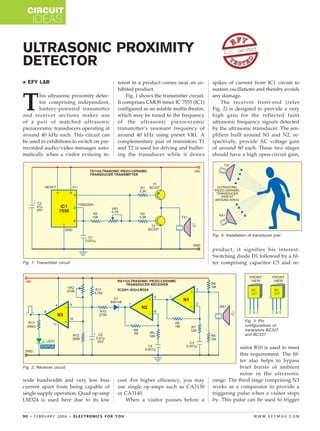
Fig. 4: Installation of transducer pair
wide bandwidth and very low bias
current apart from being capable of
single-supply operation. Quad op-amp
LM324 is used here due to its low
cost. For higher efficiency, you may
use single op-amps such as CA3130
or CA3140.
When a visitor pauses before a
product, it signifies his interest.
Switching diode D1 followed by a fil-
ter comprising capacitor C5 and re-
sistor R10 is used to meet
this requirement. The fil-
ter also helps to bypass
brief bursts of ambient
noise in the ultrasonic
range. The third stage comprising N3
works as a comparator to provide a
triggering pulse when a visitor stops
by. This pulse can be used to trigger
2. CIRCUIT
IDEAS
ELECTRONICS FOR YOU • FEBRUARY 2006 • 91W W W . E F Y M A G . C O M
CMYK
a timer or a monostable, whose out-
put may then be used to switch on
the audio/video message concerning
the product for a predetermined pe-
riod.
When somebody comes in front
of the ultrasonic piezoceramic trans-
ducer pair, the status LED (LED1)
glows because of the signal reflected
from the body of the visitor.
The circuit can be
assembled on any general-purpose
PCB. The transmitter and the receiver
should be aligned such that the trans-
mitted ultrasonic signal is optimally
received by the receiver after reflec-
tion. Fig. 3 shows the pin configura-
tion of transistors T1 and T2, while Fig.
4 shows installation of the ultrasonic
piezoceramic transducer pair operat-
ing at around 40 kHz.