This document provides an overview of aerial photogrammetry and discusses ground control points (GCPs) and flight planning. It can be summarized as follows:
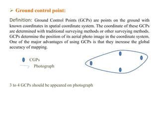
1) GCPs are points on the ground with known coordinates that are used to georeference aerial photographs. GCPs increase the overall accuracy of maps produced from aerial photos.
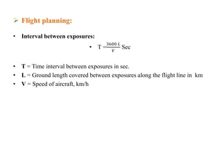
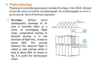
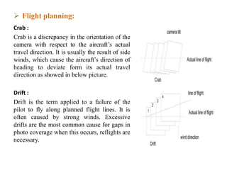
2) Flight planning involves determining the optimal altitude, overlaps between photos, and interval between exposures to ensure full coverage of the target area. Factors like wind and drift must be considered.
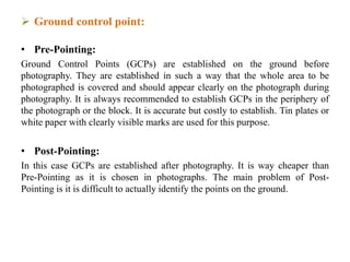
3) GCPs can be established before or after photography, and both horizontal and vertical control is needed with an ideal distribution across the project area. At least 3-4 G


![ Flight planning:
Altitude of aircraft: Flying altitude (H) = Contour interval x C- Factor
C- Factor varies from 500 to 1500
or can be calculated from equation of scale, S =
𝐹
𝐻 −ℎ
Area covered by one photograph:
• Area covered by one photograph = [ length x scale ] [ width x scale ]
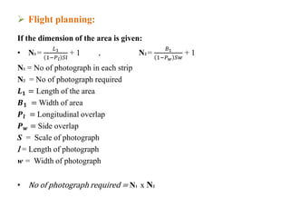
No of photograph required to cover a given area:
• Net length covered by each photographs (L) = (1-Pl ) S l
• Net width covered by each photographs (w) = (1-Pw ) S w
Pl =Longitudinal overlap, Pw = side overlap S = Scale of a photograph
l = Length of photograph in the direction of flight
w = Width of photograph normal to direction of flight](https://image.slidesharecdn.com/aerialphotogrammetry04-200405105628/85/Aerial-photogrammetry-04-8-320.jpg)