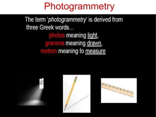
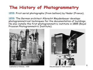
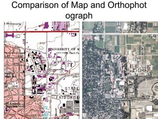
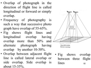
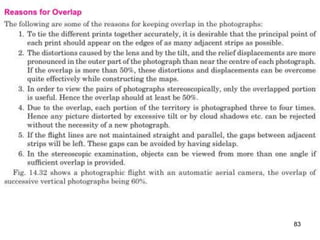
AERIAL PHOTOGRAMMETRY
MODULE - IV
1
By
Abdul Mujeeb
Asst Prof.
Dept Civil Engineering
KVGCE
Photogrammetry
2
Photogrammetry
3
Photogrammetry
4
5
6
7
8
9
10
11
12
13
14
15
16
17
18
19
20
Aerial Photogrammetry
•It is branch of Photogrammetry wherein photographs
are taken by camera mounted in aircraft flying over
the area.
•Mapping from this best mapping procedure for large
projects.
•Major users are civilian and military mapping
agencies of government.
• Used successfully for maps varying in scale from 1:1,00
0,000 1:120 with contour intervals as small as 1 foot.
• Topographic mapping is the most common form. – U.S.
G.S updated and done this way.
• Used to reconstruct a scaled 3-dimensional optical mode
l of the lands surface using a stereoplotter.
21
22
23
24
Topographic mapping
25
Architectural drawings from photogr
aphic measurements
Then Now 26
27
Close range photogrammetry
28
29
30
31
Orthophotographs
32
Comparison of Map and Orthophot
ograph
33
34
Engineering Construction
35
36
Aerial Camera
37
Essential Parts
• Lens Assembly-Lenses, Diaphragm,
Shutter and filter
• The camera cone
• Focal plane
• Camera body
• Drive mechanism
• Magazine
38
Shutter- Controls interval of time during which
light is allowed to pass through lens.
Diaphragm- Placed between lens elements and
acts as physical opening of lens system. Can
be rotated to increase or decrease size of
opening to control rays to pass through lens.
Filter- Colored glass placed in front of lens to
filter stray light in atmosphere and also flying
particles.
Camera cone-Supports entire lens including
the filter 39
Focal plane-Collimation marks at upper
surface of the cone.
Camera body- Part of camera provided at top
of cone.
Drive mechanism- It is housed in camera body
and is used for winding, tripping the shutter,
operating vacuum system for flattening film,
winding the film.
Magazine- Holds exposed and unexposed
films and houses the film flattening device at
focal plane. 40
Aerial Camera
41
Definitions
►Vertical photograph-Made with camera axis coinciding
with direction of gravity
►Tilted photograph- Made with camera axis
unintentionally tilted from vertical by small amount
(less than 3°)
►Oblique photograph- Made with camera axis directed
intentionally between horizontal and vertical.
►Perspective projection- It is produced by straight lines
radiating from common point and passing through
point on the sphere to plane of projection
(Ex:Photograph)
42
43
►Exposure station (o) : The point in the atmosphere
occupied by center of camera lenses at instance of
photography.
►Flying height : Vertical distance between exposure
station and mean sea level or any other datum.
►Flight line: Line traced by exposure station in
atmosphere ( track of aircraft)
►Focal length-It is distance between nodal point of lens
to plane of photograph(OK)
►Photo principal plane (k) It is point on photograph
obtained by projecting camera axis to intersect at a
point on photograph known as photo principal point(k)
►Camera axis extended up to ground, the point
obtained on ground is called Ground Principal point (K)44
►Plane defined by lens(O), ground nadir point (N) and
principal point produced to ground (K) ie plane NOK
►Nadir point (n)- Point where plumb line dropped front
nodal point intersects photograph
►Photo nadir point (N) : It is a point on photograph
obtained by dropping vertical line from camera center.
That plumb line extended up to ground gives Ground
Nadir Point (N)
►Tilt- Vertical angle by intersection at exposure station of
optical axis with plumb line- (angle kon=t )
►Principal line- Is the line of intersection of principal plane
with plane of photograph. Line joining principal point and
photo nadir point. (nk)
45
►Isocentre- Is the point in which bisector of angle of tilt
meets the photograph(oi). Isocentre lies on principal line at
distance of f*tan(t/2). In vertical photograph Isocentre and
photo nadir point coincide with principal point.
►Azimuth : (A) : Clockwise horizontal angle measured about
ground nadir point from true north to the principal plane of
photograph.(Ф )
►Swing (S) :-Angle measured in plane of photograph from +y
axis clockwise to photo nadir point.
►Horizon point (h) : It is point of intersection of horizontal
line through center of lenses and principal line (np) on
photograph.
►Axis of tilt:- It is line in plane of photograph perpendicular
to principal line at the Isocentre (i1 i i2)
46
47
48
49
50
51
52
A vertical photograph
53
54
55
56
An oblique photograph
57
58
SCALE OF
VERTICAL PHOTOGRAPH
►Photograph is perspective projection, images of ground
points are displaced where there are variations in
ground elevations.
►Therefore there is no uniform scale between points on
photograph except points are at same elevations.
►If elevations of points vary, scale of vertical photograph
will vary from point to point on photograph.
► when ground is horizontal, all points having same
elevation, S=scale=map distance/ground distance
59
60
61
62
Ground Co-ordinates
63
64
65
• We have seen that if the photograph is truly vertical and
the ground is horizontal,
• the scale of the photograph ,will be uniform. Such a
photograph represents a true orthographic projection
• In actual practice, however, such conditions are never
fulfilled.
• When the ground is not. horizontal. the, scale of the
photograph varies from point to point and is not constant.
Since the photograph is perspective view, the ground relief
is shown in perspective on photograph.
• Every point on the phototroph is therefore displaced from
their true orthographic position. This displacement is
called relief displacement.
66
67
68
69
70
71
72
OR LENGTH FROM GROUND CO-ORDINATES
73
74
75
76
Procedure of Aerial Survey :-
The procedure of aerial survey consists of the followings
sections:
a) Establishing ground control
b) Flight planning and photography- Overlap
c) Photo interpretation
d) Stereoscopy
e) Construction of map and cartography
77
• Ground control survey includes locating points on the
ground which can be identified on aerial photographs
• It is essential to establishing and orientation of photographs
on ground.
• Ground control extent depends on scale of map, navigation
control and cartographical process of producing maps
• Establishing ground points is divided in to 2 parts
(a) Basic control (b) Photo control
• Basic control- establishing triangulation stations, traverse
stations, azimuth marks, benchmarks etc.
• Photo control- establishing horizontal or elevations of
identified points in photograph w.r.t to basic control.
• These control introduces horizontal control and vertical
control- basic horizontal and vertical control, horizontal and
vertical photo control respectively
Establishing Ground Control
78
• Elevations of vertical control points- carrying levels from
benchmarks.
• Horizontal photo control points are located w.r.t basic
control by third fourth order triangulation, third order
traversing, trigonometric levelling etc.
• Vertical photo control points are located by third order
leveling, fly leveling etc.
• Established in 2 methods (a) Post-marking (b) Pre-marking
• (a) Post-marking method- photo control points are selected
after aerial photography. Advantage- positive identification
and favorable location of points.
• (b) Pre-marking- photo control points are selected first &
then included in photograph.
• Marks on ground should be marked with paints, flags etc so
that they can be easily identified on photograph. 79
Flight planning consists of the following information :-
a) The area to be surveyed
b) Focal length of the camera
c) Scale of the photograph
d) Longitudinal and side overlap
e) Approximate ground speed of the aircraft in stable air.
The above information is required to find the altitude of the
aircraft above datum, time interval between the exposures, the
area covered by each photograph, number of photographs
number of strips and air base. To cover the entire terrain to be
surveyed, sufficient photographs with suitable overlap should
be taken.
80
• When maps are prepared from
vertical photographs, plumb
points of preceding and succee
ding prints should visible in
each photograph.
• Photographs are taken in
intervals along each strip such
that desired overlap is obtained
in each strip.
• Strips are placed at
predetermined distances to get
desired overlap.
• Overlap of photograph in the di
rection of flight line is called
Overlap
81
• Overlap of photograph in the
direction of flight line is called
longitudinal or forward or simply
overlap.
• Frequency of photography is
such a way that successive photo
graph have overlap of 55-65%.
• Fig shows flight lines and
longitudinal overlap having
overlap more than 50% and
alternate photograph having
overlap by another 10-30%.
• Overlap between adjacent flight
line is called lateral overlap or
side overlap. Side overlap is
about 15-35%.
• Fig shows overlap
between three flight
lines 82
83
Photographic interpretation
• Photographic interpretation means identifying and
recognizing objects in the aerial photograph and then
judging their significance in photograph.
• Applications- Identification of land form, study of site
conditions, density and type of vegetation cover, location of
site for boreholes etc.
• Oblique photos- easy to interpret- pictorial form
• Color photo- easy
• Requires training, experience, imagination, patience,
observation
• Characteristics of photo images- Shape , size, pattern,
shadow, texture, site (surroundings).
• Photo interpretation is done with using magnifiers.
84
Stereoscopy and Parallax
•Stereoscopic vision- similar to
binocular vision, enables observer
to view an object or to be more
precise, 2 different perspectives of
an object, so as obtain mental
impression of 3 dimensional
image.
•Stereoscopic vision- third
dimension i.e. depth or height is
obtained by principle of parallax.
•Angle of Parallax- Apparent
movement of a point viewed first
with one eye and then with another
is known as parallax.
85
86
Stereoscopic Fusion
• Principle of this vision can be applied to photogrammetry.
• If pair of photographs of objects are taken at two different
positions of camera and then viewed by an apparatus, in
which left eyes sees only left hand picture and right eye sees
only right hand picture. These 2 separate images are fused
together in brain to provide observer with spatial impression
• This is known as stereoscopic fusion and pairs of two such
photographs is known as stereopair.
• Devices used this are stereoscope and anaglyph.
87
Stereoscope
88
Anaglyph
89
Stereoscope
• It is an instrument used for viewing stereopairs.
• They are designed for 2 purposes
1. Assist in presenting to the eyes of observer,the images of
pair of photographs so that it object in photograph visible
as same as it be natural vision.
2. To magnify the perception of depth.
• Two basic types of stereoscope are
(1) Mirror stereoscope (2) Lens stereoscope
90
Mirror Stereoscope
91
• Consists of small eye-
piece mirrors m and mꞌ
and M and Mꞌ which is
oriented 45° with plane of
photograph.
• Fig shows nail mounted
on timber block.
• Lens is kept first in
position of left eye and
then right eye,
photographs are taken.
• In photo head of nail is at
different positions
92
• 2 negative prints are
placed in stereoscope.
• Images of nail are only
observed.
• Four mirrors transfer light
to eyes exactly as if it had
come from nail as shown
by dotted line.
• Convergence and retinal
disparity enables observer
to see nail in 3 dimensions
93
Lens Stereoscope • Consists of single
magnifying lens for each
eye and no mirrors.
• Distance between 2 lenses
can be varied according to
distance between eyes of
observer.
• Distance between nodal
point and photograph
depends upon focal length
of lens.
• Disadvantage- strain to
eyes.
• Advantage- small in size,
easy to carry 94
95
Parallax
• Parallax of a point is displacement of a image of
point in 2 successive exposures.
• Difference between displacements of images of two
points on successive exposures is called difference
in parallax.
96
97
• This point to point difference in parallax between
points of stereopairs makes possible to view photos
stereoscopically to get impression of 3 dimensional
image of a terrain.
• Ideal conditions for getting aerial stereoscopic views
of ground surface
1. 2 photographs taken with suitable overlap
2. Elevations of camera positions remains same for
two exposures
3. Camera axis is vertical so that picture plane lies in
the same plane of horizontal plane.
98
99
100
101
102
• Vertical photograph can be fitted together to form map like
photograph of ground.
• Getting series of such overlapping photographs is called
mosaic.
• It is a map substitute to varying degree of accuracy.
• If photographs are taken at different altitudes they do not fit
well. It is best to re-photograph to bring to proper scale.
• Controlled mosaic is obtained when photographs are
carefully assembled so that horizontal points agree with
previously plotted points.
• Uncontrolled mosaic- Assembled without any regards of
control.
• Index mosaic- photograph laid in sequence as to allow photo
number and flight number on finished assembly. It is form
of uncontrolled mosaic
103
104
THANK YOU
105

Aerial Photogrammetry

  • 1.
    AERIAL PHOTOGRAMMETRY MODULE -IV 1 By Abdul Mujeeb Asst Prof. Dept Civil Engineering KVGCE
  • 2.
  • 3.
  • 4.
  • 5.
  • 6.
  • 7.
  • 8.
  • 9.
  • 10.
  • 11.
  • 12.
  • 13.
  • 14.
  • 15.
  • 16.
  • 17.
  • 18.
  • 19.
  • 20.
  • 21.
    Aerial Photogrammetry •It isbranch of Photogrammetry wherein photographs are taken by camera mounted in aircraft flying over the area. •Mapping from this best mapping procedure for large projects. •Major users are civilian and military mapping agencies of government. • Used successfully for maps varying in scale from 1:1,00 0,000 1:120 with contour intervals as small as 1 foot. • Topographic mapping is the most common form. – U.S. G.S updated and done this way. • Used to reconstruct a scaled 3-dimensional optical mode l of the lands surface using a stereoplotter. 21
  • 22.
  • 23.
  • 24.
  • 25.
  • 26.
    Architectural drawings fromphotogr aphic measurements Then Now 26
  • 27.
  • 28.
  • 29.
  • 30.
  • 31.
  • 32.
  • 33.
    Comparison of Mapand Orthophot ograph 33
  • 34.
  • 35.
  • 36.
  • 37.
  • 38.
    Essential Parts • LensAssembly-Lenses, Diaphragm, Shutter and filter • The camera cone • Focal plane • Camera body • Drive mechanism • Magazine 38
  • 39.
    Shutter- Controls intervalof time during which light is allowed to pass through lens. Diaphragm- Placed between lens elements and acts as physical opening of lens system. Can be rotated to increase or decrease size of opening to control rays to pass through lens. Filter- Colored glass placed in front of lens to filter stray light in atmosphere and also flying particles. Camera cone-Supports entire lens including the filter 39
  • 40.
    Focal plane-Collimation marksat upper surface of the cone. Camera body- Part of camera provided at top of cone. Drive mechanism- It is housed in camera body and is used for winding, tripping the shutter, operating vacuum system for flattening film, winding the film. Magazine- Holds exposed and unexposed films and houses the film flattening device at focal plane. 40
  • 41.
  • 42.
    Definitions ►Vertical photograph-Made withcamera axis coinciding with direction of gravity ►Tilted photograph- Made with camera axis unintentionally tilted from vertical by small amount (less than 3°) ►Oblique photograph- Made with camera axis directed intentionally between horizontal and vertical. ►Perspective projection- It is produced by straight lines radiating from common point and passing through point on the sphere to plane of projection (Ex:Photograph) 42
  • 43.
  • 44.
    ►Exposure station (o): The point in the atmosphere occupied by center of camera lenses at instance of photography. ►Flying height : Vertical distance between exposure station and mean sea level or any other datum. ►Flight line: Line traced by exposure station in atmosphere ( track of aircraft) ►Focal length-It is distance between nodal point of lens to plane of photograph(OK) ►Photo principal plane (k) It is point on photograph obtained by projecting camera axis to intersect at a point on photograph known as photo principal point(k) ►Camera axis extended up to ground, the point obtained on ground is called Ground Principal point (K)44
  • 45.
    ►Plane defined bylens(O), ground nadir point (N) and principal point produced to ground (K) ie plane NOK ►Nadir point (n)- Point where plumb line dropped front nodal point intersects photograph ►Photo nadir point (N) : It is a point on photograph obtained by dropping vertical line from camera center. That plumb line extended up to ground gives Ground Nadir Point (N) ►Tilt- Vertical angle by intersection at exposure station of optical axis with plumb line- (angle kon=t ) ►Principal line- Is the line of intersection of principal plane with plane of photograph. Line joining principal point and photo nadir point. (nk) 45
  • 46.
    ►Isocentre- Is thepoint in which bisector of angle of tilt meets the photograph(oi). Isocentre lies on principal line at distance of f*tan(t/2). In vertical photograph Isocentre and photo nadir point coincide with principal point. ►Azimuth : (A) : Clockwise horizontal angle measured about ground nadir point from true north to the principal plane of photograph.(Ф ) ►Swing (S) :-Angle measured in plane of photograph from +y axis clockwise to photo nadir point. ►Horizon point (h) : It is point of intersection of horizontal line through center of lenses and principal line (np) on photograph. ►Axis of tilt:- It is line in plane of photograph perpendicular to principal line at the Isocentre (i1 i i2) 46
  • 47.
  • 48.
  • 49.
  • 50.
  • 51.
  • 52.
  • 53.
  • 54.
  • 55.
  • 56.
  • 57.
  • 58.
  • 59.
    SCALE OF VERTICAL PHOTOGRAPH ►Photographis perspective projection, images of ground points are displaced where there are variations in ground elevations. ►Therefore there is no uniform scale between points on photograph except points are at same elevations. ►If elevations of points vary, scale of vertical photograph will vary from point to point on photograph. ► when ground is horizontal, all points having same elevation, S=scale=map distance/ground distance 59
  • 60.
  • 61.
  • 62.
  • 63.
  • 64.
  • 65.
  • 66.
    • We haveseen that if the photograph is truly vertical and the ground is horizontal, • the scale of the photograph ,will be uniform. Such a photograph represents a true orthographic projection • In actual practice, however, such conditions are never fulfilled. • When the ground is not. horizontal. the, scale of the photograph varies from point to point and is not constant. Since the photograph is perspective view, the ground relief is shown in perspective on photograph. • Every point on the phototroph is therefore displaced from their true orthographic position. This displacement is called relief displacement. 66
  • 67.
  • 68.
  • 69.
  • 70.
  • 71.
  • 72.
  • 73.
    OR LENGTH FROMGROUND CO-ORDINATES 73
  • 74.
  • 75.
  • 76.
  • 77.
    Procedure of AerialSurvey :- The procedure of aerial survey consists of the followings sections: a) Establishing ground control b) Flight planning and photography- Overlap c) Photo interpretation d) Stereoscopy e) Construction of map and cartography 77
  • 78.
    • Ground controlsurvey includes locating points on the ground which can be identified on aerial photographs • It is essential to establishing and orientation of photographs on ground. • Ground control extent depends on scale of map, navigation control and cartographical process of producing maps • Establishing ground points is divided in to 2 parts (a) Basic control (b) Photo control • Basic control- establishing triangulation stations, traverse stations, azimuth marks, benchmarks etc. • Photo control- establishing horizontal or elevations of identified points in photograph w.r.t to basic control. • These control introduces horizontal control and vertical control- basic horizontal and vertical control, horizontal and vertical photo control respectively Establishing Ground Control 78
  • 79.
    • Elevations ofvertical control points- carrying levels from benchmarks. • Horizontal photo control points are located w.r.t basic control by third fourth order triangulation, third order traversing, trigonometric levelling etc. • Vertical photo control points are located by third order leveling, fly leveling etc. • Established in 2 methods (a) Post-marking (b) Pre-marking • (a) Post-marking method- photo control points are selected after aerial photography. Advantage- positive identification and favorable location of points. • (b) Pre-marking- photo control points are selected first & then included in photograph. • Marks on ground should be marked with paints, flags etc so that they can be easily identified on photograph. 79
  • 80.
    Flight planning consistsof the following information :- a) The area to be surveyed b) Focal length of the camera c) Scale of the photograph d) Longitudinal and side overlap e) Approximate ground speed of the aircraft in stable air. The above information is required to find the altitude of the aircraft above datum, time interval between the exposures, the area covered by each photograph, number of photographs number of strips and air base. To cover the entire terrain to be surveyed, sufficient photographs with suitable overlap should be taken. 80
  • 81.
    • When mapsare prepared from vertical photographs, plumb points of preceding and succee ding prints should visible in each photograph. • Photographs are taken in intervals along each strip such that desired overlap is obtained in each strip. • Strips are placed at predetermined distances to get desired overlap. • Overlap of photograph in the di rection of flight line is called Overlap 81
  • 82.
    • Overlap ofphotograph in the direction of flight line is called longitudinal or forward or simply overlap. • Frequency of photography is such a way that successive photo graph have overlap of 55-65%. • Fig shows flight lines and longitudinal overlap having overlap more than 50% and alternate photograph having overlap by another 10-30%. • Overlap between adjacent flight line is called lateral overlap or side overlap. Side overlap is about 15-35%. • Fig shows overlap between three flight lines 82
  • 83.
  • 84.
    Photographic interpretation • Photographicinterpretation means identifying and recognizing objects in the aerial photograph and then judging their significance in photograph. • Applications- Identification of land form, study of site conditions, density and type of vegetation cover, location of site for boreholes etc. • Oblique photos- easy to interpret- pictorial form • Color photo- easy • Requires training, experience, imagination, patience, observation • Characteristics of photo images- Shape , size, pattern, shadow, texture, site (surroundings). • Photo interpretation is done with using magnifiers. 84
  • 85.
    Stereoscopy and Parallax •Stereoscopicvision- similar to binocular vision, enables observer to view an object or to be more precise, 2 different perspectives of an object, so as obtain mental impression of 3 dimensional image. •Stereoscopic vision- third dimension i.e. depth or height is obtained by principle of parallax. •Angle of Parallax- Apparent movement of a point viewed first with one eye and then with another is known as parallax. 85
  • 86.
  • 87.
    Stereoscopic Fusion • Principleof this vision can be applied to photogrammetry. • If pair of photographs of objects are taken at two different positions of camera and then viewed by an apparatus, in which left eyes sees only left hand picture and right eye sees only right hand picture. These 2 separate images are fused together in brain to provide observer with spatial impression • This is known as stereoscopic fusion and pairs of two such photographs is known as stereopair. • Devices used this are stereoscope and anaglyph. 87
  • 88.
  • 89.
  • 90.
    Stereoscope • It isan instrument used for viewing stereopairs. • They are designed for 2 purposes 1. Assist in presenting to the eyes of observer,the images of pair of photographs so that it object in photograph visible as same as it be natural vision. 2. To magnify the perception of depth. • Two basic types of stereoscope are (1) Mirror stereoscope (2) Lens stereoscope 90
  • 91.
  • 92.
    • Consists ofsmall eye- piece mirrors m and mꞌ and M and Mꞌ which is oriented 45° with plane of photograph. • Fig shows nail mounted on timber block. • Lens is kept first in position of left eye and then right eye, photographs are taken. • In photo head of nail is at different positions 92
  • 93.
    • 2 negativeprints are placed in stereoscope. • Images of nail are only observed. • Four mirrors transfer light to eyes exactly as if it had come from nail as shown by dotted line. • Convergence and retinal disparity enables observer to see nail in 3 dimensions 93
  • 94.
    Lens Stereoscope •Consists of single magnifying lens for each eye and no mirrors. • Distance between 2 lenses can be varied according to distance between eyes of observer. • Distance between nodal point and photograph depends upon focal length of lens. • Disadvantage- strain to eyes. • Advantage- small in size, easy to carry 94
  • 95.
  • 96.
    Parallax • Parallax ofa point is displacement of a image of point in 2 successive exposures. • Difference between displacements of images of two points on successive exposures is called difference in parallax. 96
  • 97.
  • 98.
    • This pointto point difference in parallax between points of stereopairs makes possible to view photos stereoscopically to get impression of 3 dimensional image of a terrain. • Ideal conditions for getting aerial stereoscopic views of ground surface 1. 2 photographs taken with suitable overlap 2. Elevations of camera positions remains same for two exposures 3. Camera axis is vertical so that picture plane lies in the same plane of horizontal plane. 98
  • 99.
  • 100.
  • 101.
  • 102.
  • 103.
    • Vertical photographcan be fitted together to form map like photograph of ground. • Getting series of such overlapping photographs is called mosaic. • It is a map substitute to varying degree of accuracy. • If photographs are taken at different altitudes they do not fit well. It is best to re-photograph to bring to proper scale. • Controlled mosaic is obtained when photographs are carefully assembled so that horizontal points agree with previously plotted points. • Uncontrolled mosaic- Assembled without any regards of control. • Index mosaic- photograph laid in sequence as to allow photo number and flight number on finished assembly. It is form of uncontrolled mosaic 103
  • 104.
  • 105.