Basic principles of
Photogrammetry
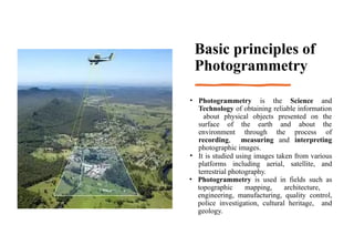
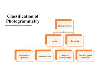
•Photogrammetry is the Science and
Technology of obtaining reliable information
about physical objects presented on the
surface of the earth and about the
environment through the process of
recording, measuring and interpreting
photographic images.
• It is studied using images taken from various
platforms including aerial, satellite, and
terrestrial photography.
• Photogrammetry is used in fields such as
topographic mapping, architecture,
engineering, manufacturing, quality control,
police investigation, cultural heritage, and
geology.
3.
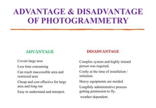
ADVANTAGE & DISADVANTAGE
OFPHOTOGRAMMETRY
ADVANTAGE
Covers large area
Less time consuming
Can reach inaccessible area and
restricted area
Cheap and cost effective for large
area and long run
Easy to understand and interpret.
DISADVANTAGE
Complex system and highly trained
person was required.
Costly at the time of installation /
initiation.
Heavy equipments are needed.
Lengthily administrative process
getting permission to fly.
weather dependent.
Terrestrial
photogrammetry
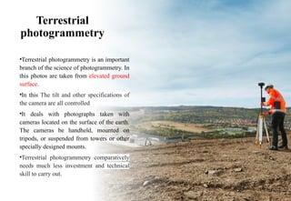
•Terrestrial photogrammetry isan important
branch of the science of photogrammetry. In
this photos are taken from elevated ground
surface.
•In this The tilt and other specifications of
the camera are all controlled
•It deals with photographs taken with
cameras located on the surface of the earth.
The cameras be handheld, mounted on
tripods, or suspended from towers or other
specially designed mounts.
•Terrestrial photogrammetry comparatively
needs much less investment and technical
skill to carry out.
6.
AERIAL
PHOTOGRAMMET
RY
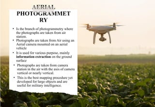
• Is thebranch of photogrammetry where
the photographs are taken from air
station.
• Photographs are taken from Air using an
Aerial camera mounted on an aerial
vehicle
• It is used for various purpose, mainly
information extraction on the ground
surface
• Photographs are taken from camera
station in the air with the axis of camera
vertical or nearly vertical.
• This is the best mapping procedure yet
developed for large objects and are
useful for military intelligence.
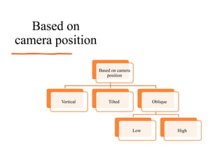
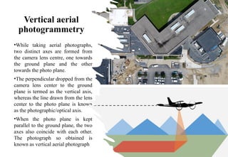
Vertical aerial
photogrammetry
•While takingaerial photographs,
two distinct axes are formed from
the camera lens centre, one towards
the ground plane and the other
towards the photo plane.
•The perpendicular dropped from the
camera lens center to the ground
plane is termed as the vertical axis,
whereas the line drawn from the lens
center to the photo plane is known
as the photographic/optical axis.
•When the photo plane is kept
parallel to the ground plane, the two
axes also coincide with each other.
The photograph so obtained is
known as vertical aerial photograph
9.
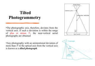
Tilted
Photogrammetry
•The photographic axis,therefore, deviates from the
vertical axis. If such a deviation is within the range
of plus or minus 3o
, the near-vertical aerial
photographs are obtained
•Any photography with an unintentional deviation of
more than 30
in the optical axis from the vertical axis
is known as a tilted photograph.
10.
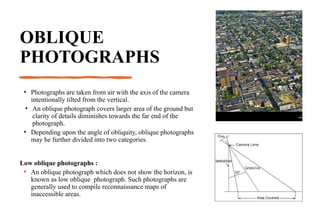
OBLIQUE
PHOTOGRAPHS
• Photographs aretaken from air with the axis of the camera
intentionally tilted from the vertical.
• An oblique photograph covers larger area of the ground but
clarity of details diminishes towards the far end of the
photograph.
• Depending upon the angle of obliquity, oblique photographs
may he further divided into two categories.
Low oblique photographs :
• An oblique photograph which does not show the horizon, is
known as low oblique photograph. Such photographs are
generally used to compile reconnaissance maps of
inaccessible areas.
11.
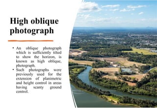
High oblique
photograph
• Anoblique photograph
which is sufficiently tilted
to show the horizon, is
known as high oblique,
photograph.
• Such photographs were
previously used for the
extension of planimetric
and height control in areas
having scanty ground
control.
12.
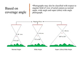
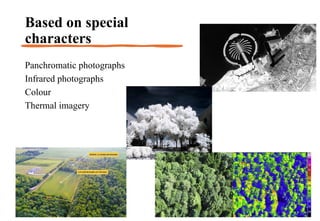
Based on
coverage angle
•Photographsmay also be classified with respect to
angular field of view of aerial camera as normal
angle, wide angle and super (ultra) wide angle
photograph.
13.
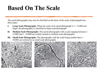
Based On TheScale
The aerial photographs may also be classified on the basis of the scale of photograph into
three types.
I. Large Scale Photographs: When the scale of an aerial photograph is 1 : 15,000 and
larger, the photography is classified as large-scale photograph
II. Medium Scale Photographs: The aerial photographs with a scale ranging between 1 :
15,000 and 1 : 30,000 are usually treated as medium scale photographs
III. Small Scale Photographs: The photographs with the scale being smaller than 1 :
30,000, are referred to as small scale photographs
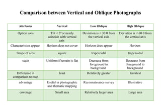
Comparison between Verticaland Oblique Photographs
Attributes Vertical Low Oblique High Oblique
Optical axis Tilt < 30
or nearly
coincide with vertical
axis
Deviation is < 30 0 from
the vertical axis
Deviation is < 60 0 from
the vertical axis
Characteristics appear Horizon does not cover Horizon does appear Horizon
Shape of area square trapezoidal trapezoidal
scale Uniform if terrain is flat Decrease from
foreground to
background
Decrease from
foreground to
background
Difference in
comparison to map
least Relatively greater Greatest
advantage Useful in photographic
and thematic mapping
Reconnaissance survey Illustrative
coverage Small area Relatively larger area Large area
16.
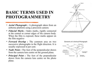
BASIC TERMS USEDIN
PHOTOGRAMMETRY
• Aerial Photograph : A photograph taken from an
airborne platform using a precision camera
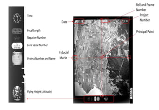
• Fiducial Marks : Index marks, rigidly connected
at the central or corner edges of the camera body.
When the film is exposed, these marks appear on
the film negative
• Forward Overlap : The common area on two
successive photographs in the flight direction. It is
usually expressed in per cent.
• Nadir Point : The foot of the perpendicular drawn
from the camera lens centre on the ground plane.
• Principal Point : The foot of the perpendicular
drawn from the camera lens centre on the photo
plane.
17.
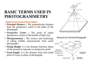
BASIC TERMS USEDIN
PHOTOGRAMMETRY
• Principal Distance : The perpendicular distance
from the perspective center to the plane of the
photograph.
• Perspective Centre : The point of origin
(perspective center) of the bundle of light rays.
• Photogrammetry : The science and technology
of taking reliable measurements from aerial
photographs.
• Flying Height: it is the distance between object
on the ground to exposure or perspective point
• Focal length: it is the distance from font nodal
point of Lense to plane of photograph.
18.
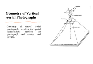
Geometry of Vertical
AerialPhotographs
Geometry of vertical aerial
photographs involves the spatial
relationships between the
photograph and camera and
ground.
20.
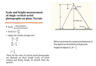
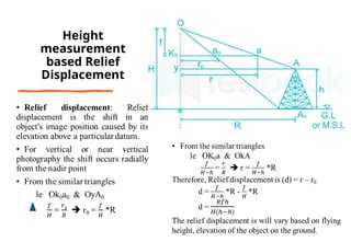
Scale and heightmeasurement
of single vertical aerial
photographs-on plane Terrain
•
21.
• A verticalaerial photograph is taken over flat terrain with a 6 in
(152.4 mm ) focal length camera from an altitude of 6000 ft above
ground. What is the photo scale?
22.
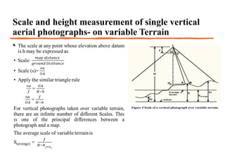
Scale and heightmeasurement of single vertical
aerial photographs- on variable Terrain
•
23.
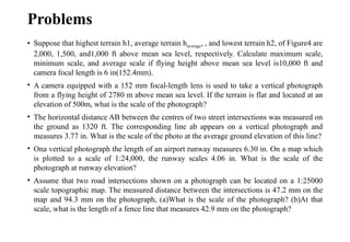
Problems
• Suppose thathighest terrain h1, average terrain haverage, , and lowest terrain h2, of Figure4 are
2,000, 1,500, and1,000 ft above mean sea level, respectively. Calculate maximum scale,
minimum scale, and average scale if flying height above mean sea level is10,000 ft and
camera focal length is 6 in(152.4mm).
• A camera equipped with a 152 mm focal-length lens is used to take a vertical photograph
from a flying height of 2780 m above mean sea level. If the terrain is flat and located at an
elevation of 500m, what is the scale of the photograph?
• The horizontal distance AB between the centres of two street intersections was measured on
the ground as 1320 ft. The corresponding line ab appears on a vertical photograph and
measures 3.77 in. What is the scale of the photo at the average ground elevation of this line?
• Ona vertical photograph the length of an airport runway measures 6.30 in. On a map which
is plotted to a scale of 1:24,000, the runway scales 4.06 in. What is the scale of the
photograph at runway elevation?
• Assume that two road intersections shown on a photograph can be located on a 1:25000
scale topographic map. The measured distance between the intersections is 47.2 mm on the
map and 94.3 mm on the photograph, (a)What is the scale of the photograph? (b)At that
scale, what is the length of a fence line that measures 42.9 mm on the photograph?
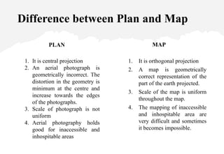
Difference between Planand Map
PLAN
1. It is central projection
2. An aerial photograph is
geometrically incorrect. The
distortion in the geometry is
minimum at the centre and
increase towards the edges
of the photographs.
3. Scale of photograph is not
uniform
4. Aerial photography holds
good for inaccessible and
inhospitable areas
MAP
1. It is orthogonal projection
2. A map is geometrically
correct representation of the
part of the earth projected.
3. Scale of the map is uniform
throughout the map.
4. The mapping of inaccessible
and inhospitable area are
very difficult and sometimes
it becomes impossible.
26.
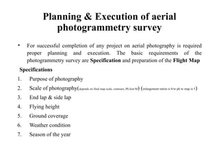
Planning & Executionof aerial
photogrammetry survey
• For successful completion of any project on aerial photography is required
proper planning and execution. The basic requirements of the
photogrammetry survey are Specification and preparation of the Flight Map
Specifications
1. Purpose of photography
2. Scale of photography(depends on final map scale, contours, Ph.Inst M) (enlargement ration is b/w ph to map is 5)
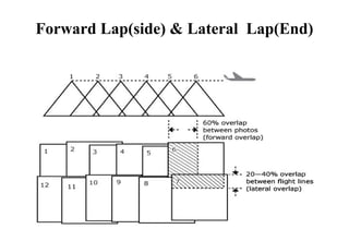
3. End lap & side lap
4. Flying height
5. Ground coverage
6. Weather condition
7. Season of the year
27.
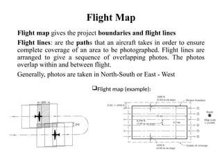
Flight Map
Flight mapgives the project boundaries and flight lines
Flight lines: are the paths that an aircraft takes in order to ensure
complete coverage of an area to be photographed. Flight lines are
arranged to give a sequence of overlapping photos. The photos
overlap within and between flight.
Generally, photos are taken in North-South or East - West
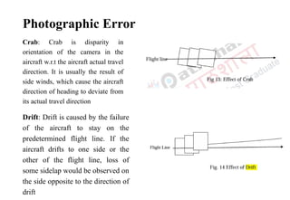
Photographic Error
Crab: Crabis disparity in
orientation of the camera in the
aircraft w.r.t the aircraft actual travel
direction. It is usually the result of
side winds, which cause the aircraft
direction of heading to deviate from
its actual travel direction
Drift: Drift is caused by the failure
of the aircraft to stay on the
predetermined flight line. If the
aircraft drifts to one side or the
other of the flight line, loss of
some sidelap would be observed on
the side opposite to the direction of
drift
30.
Fundamentals of
Stereoscope
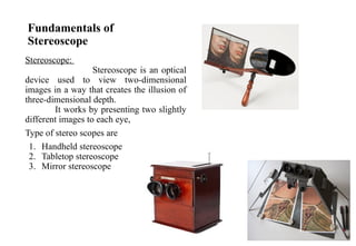
Stereoscope:
Stereoscope isan optical
device used to view two-dimensional
images in a way that creates the illusion of
three-dimensional depth.
It works by presenting two slightly
different images to each eye,
Type of stereo scopes are
1. Handheld stereoscope
2. Tabletop stereoscope
3. Mirror stereoscope
31.
Stereoscopy and StereoscopicVision
Stereoscopy, sometimes called stereoscopic imaging, is a technique
used to enable a three-dimensional effect, adding an illusion of depth
to a flat image.
A stereoscope facilitates the stereoviewing process by looking at the
left image with the left eye and the right image with the right eye
Stereo viewing allows the human brain to judge and perceive in depth
and volume
32.
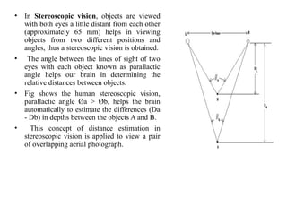
• In Stereoscopicvision, objects are viewed
with both eyes a little distant from each other
(approximately 65 mm) helps in viewing
objects from two different positions and
angles, thus a stereoscopic vision is obtained.
• The angle between the lines of sight of two
eyes with each object known as parallactic
angle helps our brain in determining the
relative distances between objects.
• Fig shows the human stereoscopic vision,
parallactic angle Øa > Øb, helps the brain
automatically to estimate the differences (Da
- Db) in depths between the objects A and B.
• This concept of distance estimation in
stereoscopic vision is applied to view a pair
of overlapping aerial photograph.
33.
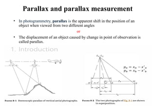
Parallax and parallaxmeasurement
• In photogrammetry, parallax is the apparent shift in the position of an
object when viewed from two different angles
or
• The displacement of an object caused by change in point of observation is
called parallax.
34.
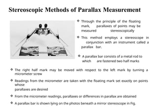
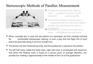
Through theprinciple of the floating
mark, parallaxes of points may be
measured stereoscopically
This method employs a stereoscope in
conjunction with an instrument called a
parallax bar.
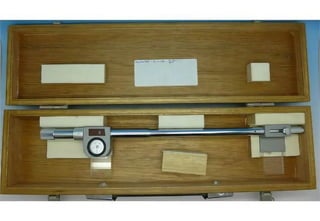
A parallax bar consists of a metal rod to
which are fastened two half marks
The right half mark may be moved with respect to the left mark by turning a
micrometer screw
Readings from the micrometer are taken with the floating mark set exactly on points
whose
parallaxes are desired
From the micrometer readings, parallaxes or differences in parallax are obtained
A parallax bar is shown lying on the photos beneath a mirror stereoscope in Fig.
Seoul National
University
Stereoscopic Methods of Parallax Measurement
36.
When aparallax bar is used, the two photos of a stereopair are first carefully oriented
for comfortable stereoscopic viewing, in such a way that the flight line of each
photo lies precisely along a common straight line
The photos are then fastened securely, and the parallax bar is placed on the photos
The left half mark, called the fixed mark, right half mark is unclamped and moved so
that when the floating mark is fused on a terrain point of average elevation, the
parallax bar reading is approximately in the middle of the run of the graduations
Stereoscopic Methods of Parallax Measurement
Through the principle of the floating
mark, parallaxes of points may be
measured stereoscopically
This method employs a stereoscope in
conjunction with an instrument called a
parallax bar, also frequently called a
stereometer
A parallax bar consists of a metal rod to
which are fastened two half marks
37.
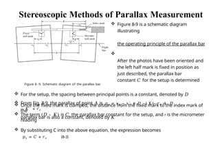
The term(𝐷 – 𝐾) is 𝐶, the parallax bar constant for the setup, and r is the micrometer
reading
By substituting C into the above equation, the expression becomes
𝑝𝑎 = 𝐶 + 𝑟𝑎 (8-3)
Stereoscopic Methods of Parallax Measurement
Figure 8-9 is a schematic diagram
illustrating
the operating principle of the parallax bar
After the photos have been oriented and
the left half mark is fixed in position as
just described, the parallax bar
constant 𝐶 for the setup is determined
Figure 8 - 9. Schematic diagram of the parallax bar.
For the setup, the spacing between principal points is a constant, denoted by 𝐷
Once the fixed mark is clamped, the distance from the fixed mark to the index mark of
the
parallax bar is also a constant, denoted by 𝐾
𝑎
From Fig. 8-9, the parallax of point 𝐴 is 𝑝𝑎 = 𝑥𝑎 − 𝑥′ = 𝐷 − K − 𝑟𝑎 = 𝐷
− 𝐾 + 𝑟𝑎
38.
Stereoscopic Methods ofParallax Measurement
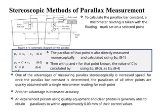
Figure 8 - 9. Schematic diagram of the parallax
bar.
To calculate the parallax bar constant, a
micrometer reading is taken with the
floating mark set on a selected point
𝐶 = 𝑝
− 𝑟
(8-4)
𝑝𝑎 = 𝑥𝑎 − 𝑥𝑎
′ (8-1)
𝑝𝑎 = 𝐶 + 𝑟𝑎 (8-3)
One of the advantages of measuring parallax stereoscopically is increased speed, for
once the parallax bar constant is determined, the parallaxes of all other points are
quickly obtained with a single micrometer reading for each point
Another advantage is increased accuracy
An experienced person using quality equipment and clear photos is generally able to
obtain parallaxes to within approximately 0.03 mm of their correct values
The parallax of that point is also directly measured
monoscopically and calculated using Eq. (8-1)
Then with p and r for that point known, the value of C is
calculated by using Eq. (8-3), as Eq. (8-4)