Downloaded 1,179 times


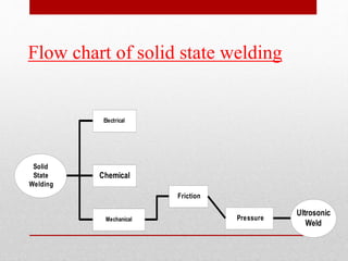
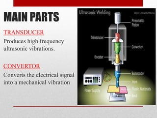
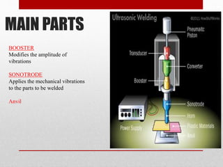
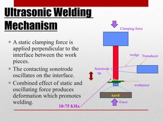
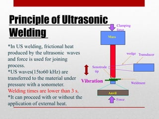
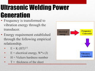
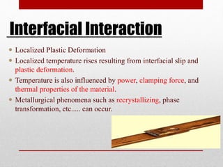

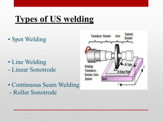
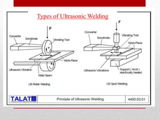


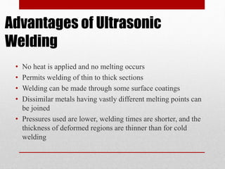
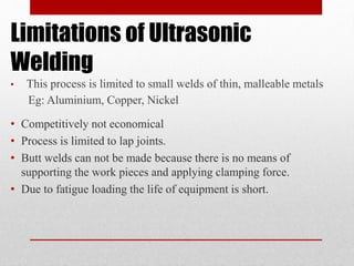
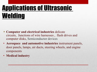


Ultrasonic welding is a solid-state welding technique that utilizes high-frequency acoustic vibrations to join materials under pressure, enabling fast and efficient bonding without the need for additional materials like bolts or adhesives. The process involves components such as transducers, sonotrodes, and anvils to create localized plastic deformation and heat at the weld site. While offering advantages like joining dissimilar metals and faster welding times, ultrasonic welding has limitations including economic viability and the inability to create certain joint types.


