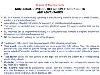
MANUFACTURING PROCESSES-II
Engr. Umair
What is Manufacturing?
 The word manufacturing is derived from two latin words, manus (hand) and factus (make), the
combination means made by hand.
 Manufacturing, in its broadest sense, is the process of converting raw materials into products.
 Manufacturing can be defined two ways, one technologic and other economic.
- Technologically, manufacturing is the application of physical and chemical processes to alter the
geometry, properties and appearance of a given starting material to make parts or products;
manufacturing also includes assembly of multiple parts to make products.
- Economically, manufacturing is the transformation of materials into items of greater value by
means of one or more processing and/or assembly operations.
Production vs Manufacturing
 Production engineering is a complete cycle as it involves procurement of raw material, storing
that raw material as inventory, conversion of raw into semi finished or finished goods,
dispatching, sales forecasting etc. but manufacturing is a part of production engineering which
just involves in the value addition of raw materials (conversion of raw into semi finished or
finished goods).
Chapter No. 06
CONTROL OF MACHINE TOOLS
 NC is a method of automatically operating a manufacturing machine based on a code of letters,
numbers, and special characters.
 A complete set of coded instructions for executing an operation is called a program.
 The program is translated into corresponding electrical signals for input to motors that run the
machine.
 NC machines can be programmed manually. If a computer is used to create a program, the process
is known as computer-aided programming.
 NC has been used in industry for more than 40 years.
 Traditionally, NC systems have been composed of the following components:
 Tape punch: converts written instructions into a corresponding hole pattern. The hole pattern is
punched into tape which is passed through the tape punch. Much older units used a typewriter
device called a Flexowriter, and later devices included a microcomputer coupled with a tape punch
unit.
 Tape reader: reads the hole pattern on the tape and converts the pattern to a corresponding
electrical signal code.
 Controller: receives the electrical signal code from the tape reader and subsequently causes the
NC machine to respond.
 NC machine: responds to programmed signals from the controller. Accordingly, the machine
executes the required motions to manufacture a part (spindle rotation on/off, table and or spindle
movement along programmed axis directions, etc.).
Control Of Machine Tools
NUMERICAL CONTROL DEFINITION, ITS CONCEPTS
AND ADVANTAGES
Control Of Machine Tools
Components of traditional NC systems
 Components of an NC System
1. Program of instructions
 Part program in machining
2. Machine control unit
 Controls the process
3. Processing equipment
 Performs the process
Control Of Machine Tools
 NC systems offer some advantages over manual production methods:
 Higher precision: NC machine tool are capable of machining at very close tolerances, in some
operations as small as 0.005 mm;
 Machining of complex three-dimensional shapes:
 Better quality: NC systems are capable of maintaining constant working conditions for all parts
in a batch thus ensuring less spread of quality characteristics;
 Higher productivity: NC machine tools reduce drastically the non machining time. Adjusting
the machine tool for a different product is as easy as changing the computer program and tool
turret with the new set of cutting tools required for the particular part.
 Multi-operational machining: some NC machine tools, for example machine centers, are
capable of accomplishing a very high number of machining operations thus reducing significantly
the number of machine tools in the work shops.
 Low operator qualification: the role of the operator of a NC machine is simply to upload the
work piece and to download the finished part. In some cases, industrial robots are employed for
material handling, thus eliminating the human operator.
 Types of NC systems
 Machine controls are divided into three groups,
 Traditional numerical control (NC);
Œ
 Computer numerical control(CNC);
 Distributed numerical control (DNC)
 The original numerical control machines were referred to as NC machine tool. They have
“hardwired” control, whereby control is accomplished through the use of punched paper
(or plastic) tapes or cards. Tapes tend to wear, and become dirty, thus causing
misreading.
 CNC refers to a system that has a local computer to store all required numerical data. The
advantages of CNC systems include but are not limited to the possibility to store and
execute a number of large programs (especially if a three or more dimensional machining
of complex shapes is considered), to allow editing of programs, to execute cycles of
machining commands, etc.
 Distributed numerical control is similar to CNC, except a remote computer is used to
control a number of machines. An off-site mainframe host computer holds programs for all
parts to be produced in the DNC facility. Programs are downloaded from the mainframe
computer, and then the local controller feeds instructions to the hardwired NC machine.
Control Of Machine Tools
Motion Control Systems
 Point-to-Point systems
 Also called position systems
 System moves to a location and performs an operation at that location (e.g., drilling)
 Also applicable in robotics
 Continuous path systems
 Also called contouring systems in machining
 System performs an operation during movement (e.g., milling and turning)
Control Of Machine Tools
Absolute and Incremental Positioning
 Absolute positioning
 Locations defined relative to origin of axis system
 Incremental positioning
 Locations defined relative to previous position
 Example: drilling
 The workhead is presently at point (20, 20) and is to be moved to point (40, 50)
 In absolute positioning, the move is specified by x= 40, y= 50
 In incremental positioning, the move is specified by x= 20, y= 30.
Control Of Machine Tools
 Computer Numerical Control (CNC) –Additional Features
 Storage of more than one part program
 Various forms of program input
 Program editing at the machine tool
 Fixed cycles and programming subroutines
 Interpolation
 Communications interface
 Diagnostics
Configuration of CNC Machine Control Unit
Control Of Machine Tools
 DNC
 Direct numerical control (DNC) –control of multiple machine tools by a single (mainframe)
computer through direct connection and in real time.
 1960s technology
 Two way communication
 Distributed numerical control (DNC) –network consisting of central computer connected to
machine tool MCUs, which are CNC.
 Present technology
 Two way communication
System Connection to MCU is behind the tape reader (BTR). In distributed NC, entire programs are
downloaded to each MCU, which is CNC rather than conventional NC
Control Of Machine Tools
Distributed Numerical Control Configurations
Control Of Machine Tools
 Applications of NC
 Machine tool applications:
 Milling, drilling, turning, boring, grinding
 Machining centers, turning centers, mill-turn centers
 Punch presses, thermal cutting machines, etc.
 Other NC applications:
 Component insertion machines in electronics
 Drafting machines (x-y plotters)
 Coordinate measuring machines
 Tape laying machines for polymer composites
 Filament winding machines for polymer composites
Common NC Machining Operations
Control Of Machine Tools
 NC Application Characteristics
(Machining)
 Where NC is most appropriate ?
1) Batch production
2) Repeat orders
3) Complex part geometries
4) Much metal needs to be removed from the starting workpart
5) Many separate machining operations on the part
6) The part is expensive
Control Of Machine Tools
 Advantages of NC
 Nonproductive time is reduced
 Greater accuracy and repeatability
 Lower scrap rates
 Inspection requirements are reduced
 More complex part geometries are possible
 Engineering changes are easier to make
 Simpler fixtures
 Shorter lead times
 Reduce parts inventory and less floor space
 Operator skill-level requirements are reduced
Control Of Machine Tools
 Disadvantages of NC
 Higher investment cost
 CNC machines are more expensive
 Higher maintenance effort
 CNC machines are more technologically sophisticated
 Part programming issues
 Need for skilled programmers
 Time investment for each new part
 Repeat orders are easy because part program is already available
 Higher utilization is required
Control Of Machine Tools
NC Positioning System
 Typical motor and lead screw arrangement in an NC positioning system for one linear axis
 For x-y capability, the apparatus would be piggybacked on top of a second perpendicular axis
Control Of Machine Tools
 Analysis of Positioning NC Systems
 Two types of NC positioning systems:
1) Open-loop -no feedback to verify that the actual position achieved is the desired position
2) Closed-loop -uses feedback measurements to confirm that the final position is the specified
position
 Precision in NC positioning -three measures:
1) Control resolution
2) Accuracy
3) Repeatability
Control Of Machine Tools
 Open-Loop Motion Control System
Operates without verifying that the actual position achieved in the move is the desired position
Control Of Machine Tools
 Closed-Loop Motion Control System
Uses feedback measurements to confirm that the final position of the worktable is the location
specified in the program
 Optical Encoder
 Device for measuring rotational position and speed
 Common feedback sensor for closed-loop NC control
Control Of Machine Tools
NC Part Programming
1) Manual part programming
2) Computer-assisted part programming
3) Part programming using CAD/CAM
4) Manual data input
Control Of Machine Tools
1) Manual part programming
 The programmer first prepares the manuscript in a standard format. Manuscripts are typed with
a device called flexo writer, which is also used to type the program instructions. After the
program is typed the punch tape is prepared on the flexo writer. Complex shaped components
require tedious calculations. This type of program is carried out for simple machining parts
produced on point-to-point machine tool.
 To be able to create a program manually, need the following information
a) Knowledge about various manufacturing processes and machines.
b) Sequence of operations to be performed for a given component.
c) Knowledge of the selection of cutting parameters.
d) Editing the part program according to the design changes.
e) Knowledge about the codes and functions used in the part programs.
 In manual part programming the programmer prepares the NC code using the low-level
machining language (G-M Codes)
Control Of Machine Tools
Binary Coded Decimal System
Each of the ten digits in decimal system is coded with four-digit binary number
The binary numbers are added to give the value
BCD is compatible with 8 bits across tape format, the original storage medium for NC part
programs
Eight bits can also be used for letters and symbols
Creating Instructions for NC
Bit -0 or 1 = absence or presence of hole in the tape
Character -row of bits across the tape
Word -sequence of characters (e.g., y-axis position)
Block -collection of words to form one complete instruction
Part program -sequence of instructions (blocks)
Control Of Machine Tools
Types of Words
N -sequence number prefix
G -preparatory words
 Example: G00 = PTP rapid traverse move
X, Y, Z -prefixes for x, y, and z-axes
F -feed rate prefix
S -spindle speed
T -tool selection
M -miscellaneous command
 Example: M07 = turn cutting fluid on
Example: Word Address Format
 N001 G00 X07000 Y03000 M03
 N002 Y06000
Control Of Machine Tools
Block Format
 Organization of words within a block in NC part program
 Also known as tape format because the original formats were designed for punched tape
 Word address format -used on all modern CNC controllers
 Uses a letter prefix to identify each type of word
 Spaces to separate words within the block
 Allows any order of words in a block
 Words can be omitted if their values do not change from the previous block
Control Of Machine Tools
Computer-Assisted Part Programming
 Manual part programming is time-consuming, tedious, and subject to human errors for complex
jobs
 Machining instructions are written in English-like statements that are translated by the computer
into the low-level machine code of the MCU
 APT (Automatically Programmed Tool)
 The various tasks in computer-assisted part programming are divided between
 The human part programmer
 The computer
Computer-Assisted Part Programming
Sequence of activities in computer-assisted part programming
Control Of Machine Tools
Part Programmer's Job
Two main tasks of the programmer:
1) Define the part geometry
2) Specify the tool path
1) Defining Part Geometry
 Underlying assumption: no matter how complex the part geometry, it is composed of basic
geometric elements and mathematically defined surfaces
 Geometry elements are sometimes defined only for use in specifying tool path
 Examples of part geometry definitions:
P4 = POINT/35,90,0
L1 = LINE/P1,P2
C1 = CIRCLE/CENTER,P8,RADIUS,30
2) Specifying Tool Path and Operation Sequence
 Tool path consists of a sequence of points or connected line and arc segments, using
previously defined geometry elements
 Point-to-Point command:
GOTO/P0
 Continuous path command
GOLFT/L2,TANTO,C1
Control Of Machine Tools
 Other Functions in Computer-Assisted Part Programming
 Specifying cutting speeds and feed rates
 Designating cutter size (for tool offset calculations)
 Specifying tolerances in circular interpolation
 Naming the program
 Identifying the machine tool
Control Of Machine Tools
Computer Tasks in Computer-Assisted Part Programming
1) Input translation –converts the coded instructions in the part program into computer-usable form
2) Arithmetic and cutter offset computations –performs the mathematical computations to define
the part surface and generate the tool path, including cutter offset compensation (CLFILE)
3) Editing –provides readable data on cutter locations and machine tool operating commands
(CLDATA)
4) Post processing –converts CLDATA into low-level code that can be interpreted by the MCU
Control Of Machine Tools
NC Part Programming Using CAD/CAM
 Geometry definition
 If the CAD/CAM system was used to define the original part geometry, no need to recreate
that geometry as in APT
 Automatic labeling of geometry elements
 If the CAD part data are not available, geometry must be created, as in APT, but user gets
immediate visual feedback about the created geometry
Tool Path Generation Using CAD/CAM
 Basic approach: enter the commands one by one (similar to APT)
 CAD/CAM system provides immediate graphical verification of the command
 Automatic software modules for common machining cycles
 Profile milling
 Pocket milling
 Drilling bolt circles
NC Part Programming Using CAD/CAM
Control Of Machine Tools
Examples of Machining Cycles in Automated NC Programming Modules
Pocket milling
Contour turning
Facing and shoulder facing
Threading (external)
Control Of Machine Tools
Manual Data Input
 Machine operator does part programming at machine
 Operator enters program by responding to prompts and questions by system
 Monitor with graphics verifies tool path
 Usually for relatively simple parts
 Ideal for small shop that cannot afford a part programming staff
 To minimize changeover time, system should allow programming of next job while current job
is running
Control Of Machine Tools
Example
Example of CNC Programming
What Must Be Done To Drill A Hole On A CNC Vertical
Milling Machine?
Control Of Machine Tools
Top
View
Front
View
Tool Home
1.) X & Y Rapid To Hole Position
Top
View
Front
View
2.) Z Axis Rapid Move
Just Above Hole
3.) Turn On Coolant
4.) Turn On Spindle
.100”
Top
View
Front
View
5.) Z Axis Feed Move to
Drill Hole
Top
View
Front
View
6.) Rapid Z Axis Move
Out Of Hole
Top
View
Front
View
9.) X&Y Axis Rapid
Move Home
7.) Turn Off Spindle
8.) Turn Off Coolant
Top
View
Front
View
Tool At Home
O0001
N005 G54 G90 S600 M03
N010 G00 X1.0 Y1.0
N015 G43 H01 Z.1 M08
N020 G01 Z-.75 F3.5
N030 G91 G28 X0 Y0 Z0
N035 M30
N025 G00 Z.1 M09
Here’s The CNC Program!
Top
View
Front
View
Tool At Home
O0001
O0001
Number Assigned to this program
Top
View
Front
View
Tool At Home
O0001
N005 G54 G90 S600 M03
N005 Sequence Number
G54 Fixture Offset
G90 Absolute Programming Mode
S600 Spindle Speed set to 600 RPM
M03 Spindle on in a Clockwise Direction
Top
View
Front
View
O0001
N005 G54 G90 S600 M03
N010 G00 X1.0 Y1.0
G00 Rapid Motion
X1.0 X Coordinate 1.0 in. from Zero
Y1.0 Y Coordinate 1.0 in. from Zero
Top
View
Front
View
O0001
N005 G54 G90 S600 M03
N010 G00 X1.0 Y1.0
N015 G43 H01 Z.1 M08
G43 Tool Length Compensation
H01 Specifies Tool length compensation
Z.1 Z Coordinate .1 in. from Zero
M08 Flood Coolant On
Top
View
Front
View
O0001
N005 G54 G90 S600 M03
N010 G00 X1.0 Y1.0
N015 G43 H01 Z.1 M08
N020 G01 Z-.75 F3.5
G01 Straight Line Cutting Motion
Z-.75 Z Coordinate -.75 in. from Zero
F3.5 Feed Rate set to 3.5 in./min.
Top
View
Front
View
O0001
N005 G54 G90 S600 M03
N010 G00 X1.0 Y1.0
N015 G43 H01 Z.1 M08
N020 G01 Z-.75 F3.5
G00 Rapid Motion
Z.1 Z Coordinate .1 in. from Zero
M09 Coolant Off
N025 G00 Z.1 M09
Top
View
Front
View
O0001
N005 G54 G90 S600 M03
N010 G00 X1.0 Y1.0
N015 G43 H01 Z.1 M08
N020 G01 Z-.75 F3.5
N030 G91 G28 X0 Y0 Z0
G91 Incremental Programming Mode
G28 Zero Return Command
X0, Y0, Z0
X,Y,& Z Coordinates at Zero
N025 G00 Z.1 M09
Top
View
Front
View
O0001
N005 G54 G90 S600 M03
N010 G00 X1.0 Y1.0
N015 G43 H01 Z.1 M08
N020 G01 Z-.75 F3.5
N035 M30
N030 G91 G28 X0 Y0 Z0
N025 G00 Z.1 M09
M30 End of Program
programmable logic controller (PLC) - History
 The control of manufacturing operation has traditionally been performed by devices such as
timers, switches, relays, counters, and similar hard-wired devices that are based on
mechanical, electromechanical, and pneumatic principles.
 In 1968 programmable logic controllers (PLCs) were introduced to replace these devices.
 PLC or Programmable Controller is a digital computer used for automation
of electromechanical processes, such as control of machinery on factory assembly lines.
 PLCs are used in many industries and machines.
 Unlike general-purpose computers, the PLC is designed for multiple inputs and output
arrangements, extended temperature ranges.
 Programs to control machine operation are typically stored in battery-backed-up or non-
volatile memory.
 A PLC is an example of a hard real time system since output results must be produced in
response to input conditions within a limited time, otherwise unintended operation will
result.
Control Of Machine Tools
PLC
 Areas of PLC Applications
 Motor Winding
 Baking
 Oil Fields
 Blending
 Painting
 Boring
 Palletizers
 Polishing
 Casting
 Reactors
 Chemical Drilling
 Robots
 Color Mixing
 Rolling
 Compressors
 Security Systems
 Stretch Wrap
 Conveyors
 Cranes
 Crushing
 Sorting
 Cutting
 Electronic Testing
 Threading
 Elevators
 Engine Test Stands
 Heat Treating
 Traffic Control
 Extrusion
 Textile Machine
 Forging
 Generators
 Turning
Control Of Machine Tools
 PLC and Computer
 A PLC and a computer both are electronic processor unit. The architecture of a PLC’s CPU is
basically same as that of a general purpose computer; however, some important characteristics
set them apart.
 Unlike computer, PLCs are specifically designed to survive the harsh conditions of the
industrial environment. A well-designed PLC can be placed in an area with substantial amounts
of electrical noise, electromagnetic interference, mechanical vibration, and non condensing
humidity.
 Distinction of PLCs is that their hardware and software are designed for easy use by plant
electricians and technicians. The hardware interfaces for connecting field devices are actually
part of the PLC itself and are easily connected.
 The modular and self-diagnosing interface circuits are able to pin point malfunctions and
moreover, are easily removed and replaced.
 Software programming uses conventional relay ladder symbols, or other easily learned
languages, which are familiar to plant personnel.
 A computer can execute a complex programming task and also multitasking. An standard PLC
is designed to executes a single program in an orderly fashion. As PLCs are rapidly changing,
modern PLCs have multitasking capabilities.
 Why PLCs are so Popular?
 Programmable logic controller have made it possible to precisely control large process
machines and driven equipment with less physical wiring and wiring time than it
requires with standard electro-mechanical relays, pneumatic system, timers, drum
switches, and so on.
 The programmability allows for fast and easy changes in the relay ladder logic to meet
the changing needs of the process or driven equipment without the need for expensive
and time consuming rewiring process.
 Modem PLCs are "electrician friendly", PLC can be programmed and used by plant
engineers and maintenance electricians without much electronic and computer
programming background. They can programmed by using the existing ladder
diagrams.
Control Of Machine Tools
 Advantages of PLC
 Flexibility
 Universal Controller - can replace various independent/ standalone controller.
 Implementing Changes and Correcting Errors
 Do not have to rewiring relay panel.
 Change program using keyboard.
 Large Quantity of Contact
 Large number of' Soft Contact' available.
 Lower Cost
 Advancement in technology and open architecture of PLC will reduce the
market price.
 Pilot Running (Simulation Capability)
 A program can be simulated or run without actual input connection.
 Visual Observation
 Can observe the opening and closing of contact switch on CRT .
 Operator message can be programmed for each possible malfunction.
Control Of Machine Tools
 Speed of Operation
 Depends on scan time -millisecond.
 Asynchronous operation.
 Ladder or Boolean Programming Method
 Easy for 'Electrician’.
 Reliability
 In general -very reliable
 Simplicity of Ordering Control Sys. Components
 One package with Relay, Timers, Control Block, etc.
 Documentation
 Printout of ladder logic can be printed easily
 Security
 Software lock on a program (Password)
 Ease of Changes by Programming
 Ability to program and reprogram, loading and down loading
Control Of Machine Tools
 Disadvantages of PLC
 New Technology
 Change from ladder and relay to PLC concept
 Fixed program Application
 Not cost effective for single- function application
 Environment Consideration
 Not adapted for very high temperature, high humidity level, high vibration, etc.
 Fail-safe operation
 Does not start automatically when power failure ( can be programmed into )
 Not "Fail-safe" -Fail-shorted rather than OPEN
 Fixed-circuit operation
 Fixed control system -less costly
What is a Ladder Diagram?
 A complete control scheme normally drawn as a series of contacts and coils arranged between two vertical
control supply lines so that the horizontal lines of contacts appear similar to rungs of a ladder. The control
contacts (input devices) are to left and coils (output devices) on the right. Ladder diagrams are an industrial
standard for representing relay-logic control system
Control Of Machine Tools
Programming terminal
 Programming is done through programming terminal
 Programming terminal translates engineering language (logic control) to
machine language (binary code)
Programming through standard computer
 Most PLC manufacturers offer software packages that allow a standard
computer to be used as a programming terminal
Control Of Machine Tools
An application example 1: Gate Control
 PLC can sense a vehicle at the entrance or exit, and open and close the gate automatically
 The current vehicle count is easily determined by programming a simple counter
Control Of Machine Tools
An application example 2: Conveyor System
 PLC can be used to start/stop latching logic for motor control
 Counters can be used for monitoring product amounts
Control Of Machine Tools
Module. 06.pptx OF MANUFACTURING PROCESS 2

Module. 06.pptx OF MANUFACTURING PROCESS 2

  • 1.
  • 2.
    What is Manufacturing? The word manufacturing is derived from two latin words, manus (hand) and factus (make), the combination means made by hand.  Manufacturing, in its broadest sense, is the process of converting raw materials into products.  Manufacturing can be defined two ways, one technologic and other economic. - Technologically, manufacturing is the application of physical and chemical processes to alter the geometry, properties and appearance of a given starting material to make parts or products; manufacturing also includes assembly of multiple parts to make products. - Economically, manufacturing is the transformation of materials into items of greater value by means of one or more processing and/or assembly operations. Production vs Manufacturing  Production engineering is a complete cycle as it involves procurement of raw material, storing that raw material as inventory, conversion of raw into semi finished or finished goods, dispatching, sales forecasting etc. but manufacturing is a part of production engineering which just involves in the value addition of raw materials (conversion of raw into semi finished or finished goods).
  • 3.
    Chapter No. 06 CONTROLOF MACHINE TOOLS
  • 4.
     NC isa method of automatically operating a manufacturing machine based on a code of letters, numbers, and special characters.  A complete set of coded instructions for executing an operation is called a program.  The program is translated into corresponding electrical signals for input to motors that run the machine.  NC machines can be programmed manually. If a computer is used to create a program, the process is known as computer-aided programming.  NC has been used in industry for more than 40 years.  Traditionally, NC systems have been composed of the following components:  Tape punch: converts written instructions into a corresponding hole pattern. The hole pattern is punched into tape which is passed through the tape punch. Much older units used a typewriter device called a Flexowriter, and later devices included a microcomputer coupled with a tape punch unit.  Tape reader: reads the hole pattern on the tape and converts the pattern to a corresponding electrical signal code.  Controller: receives the electrical signal code from the tape reader and subsequently causes the NC machine to respond.  NC machine: responds to programmed signals from the controller. Accordingly, the machine executes the required motions to manufacture a part (spindle rotation on/off, table and or spindle movement along programmed axis directions, etc.). Control Of Machine Tools NUMERICAL CONTROL DEFINITION, ITS CONCEPTS AND ADVANTAGES
  • 5.
    Control Of MachineTools Components of traditional NC systems  Components of an NC System 1. Program of instructions  Part program in machining 2. Machine control unit  Controls the process 3. Processing equipment  Performs the process
  • 6.
    Control Of MachineTools  NC systems offer some advantages over manual production methods:  Higher precision: NC machine tool are capable of machining at very close tolerances, in some operations as small as 0.005 mm;  Machining of complex three-dimensional shapes:  Better quality: NC systems are capable of maintaining constant working conditions for all parts in a batch thus ensuring less spread of quality characteristics;  Higher productivity: NC machine tools reduce drastically the non machining time. Adjusting the machine tool for a different product is as easy as changing the computer program and tool turret with the new set of cutting tools required for the particular part.  Multi-operational machining: some NC machine tools, for example machine centers, are capable of accomplishing a very high number of machining operations thus reducing significantly the number of machine tools in the work shops.  Low operator qualification: the role of the operator of a NC machine is simply to upload the work piece and to download the finished part. In some cases, industrial robots are employed for material handling, thus eliminating the human operator.
  • 7.
     Types ofNC systems  Machine controls are divided into three groups,  Traditional numerical control (NC); Œ  Computer numerical control(CNC);  Distributed numerical control (DNC)  The original numerical control machines were referred to as NC machine tool. They have “hardwired” control, whereby control is accomplished through the use of punched paper (or plastic) tapes or cards. Tapes tend to wear, and become dirty, thus causing misreading.  CNC refers to a system that has a local computer to store all required numerical data. The advantages of CNC systems include but are not limited to the possibility to store and execute a number of large programs (especially if a three or more dimensional machining of complex shapes is considered), to allow editing of programs, to execute cycles of machining commands, etc.  Distributed numerical control is similar to CNC, except a remote computer is used to control a number of machines. An off-site mainframe host computer holds programs for all parts to be produced in the DNC facility. Programs are downloaded from the mainframe computer, and then the local controller feeds instructions to the hardwired NC machine. Control Of Machine Tools
  • 8.
    Control Of MachineTools Motion Control Systems  Point-to-Point systems  Also called position systems  System moves to a location and performs an operation at that location (e.g., drilling)  Also applicable in robotics  Continuous path systems  Also called contouring systems in machining  System performs an operation during movement (e.g., milling and turning)
  • 9.
    Control Of MachineTools Absolute and Incremental Positioning  Absolute positioning  Locations defined relative to origin of axis system  Incremental positioning  Locations defined relative to previous position  Example: drilling  The workhead is presently at point (20, 20) and is to be moved to point (40, 50)  In absolute positioning, the move is specified by x= 40, y= 50  In incremental positioning, the move is specified by x= 20, y= 30.
  • 10.
    Control Of MachineTools  Computer Numerical Control (CNC) –Additional Features  Storage of more than one part program  Various forms of program input  Program editing at the machine tool  Fixed cycles and programming subroutines  Interpolation  Communications interface  Diagnostics Configuration of CNC Machine Control Unit
  • 11.
    Control Of MachineTools  DNC  Direct numerical control (DNC) –control of multiple machine tools by a single (mainframe) computer through direct connection and in real time.  1960s technology  Two way communication  Distributed numerical control (DNC) –network consisting of central computer connected to machine tool MCUs, which are CNC.  Present technology  Two way communication System Connection to MCU is behind the tape reader (BTR). In distributed NC, entire programs are downloaded to each MCU, which is CNC rather than conventional NC
  • 12.
    Control Of MachineTools Distributed Numerical Control Configurations
  • 13.
    Control Of MachineTools  Applications of NC  Machine tool applications:  Milling, drilling, turning, boring, grinding  Machining centers, turning centers, mill-turn centers  Punch presses, thermal cutting machines, etc.  Other NC applications:  Component insertion machines in electronics  Drafting machines (x-y plotters)  Coordinate measuring machines  Tape laying machines for polymer composites  Filament winding machines for polymer composites
  • 14.
    Common NC MachiningOperations Control Of Machine Tools
  • 15.
    Control Of MachineTools  NC Application Characteristics (Machining)  Where NC is most appropriate ? 1) Batch production 2) Repeat orders 3) Complex part geometries 4) Much metal needs to be removed from the starting workpart 5) Many separate machining operations on the part 6) The part is expensive
  • 16.
    Control Of MachineTools  Advantages of NC  Nonproductive time is reduced  Greater accuracy and repeatability  Lower scrap rates  Inspection requirements are reduced  More complex part geometries are possible  Engineering changes are easier to make  Simpler fixtures  Shorter lead times  Reduce parts inventory and less floor space  Operator skill-level requirements are reduced
  • 17.
    Control Of MachineTools  Disadvantages of NC  Higher investment cost  CNC machines are more expensive  Higher maintenance effort  CNC machines are more technologically sophisticated  Part programming issues  Need for skilled programmers  Time investment for each new part  Repeat orders are easy because part program is already available  Higher utilization is required
  • 18.
    Control Of MachineTools NC Positioning System  Typical motor and lead screw arrangement in an NC positioning system for one linear axis  For x-y capability, the apparatus would be piggybacked on top of a second perpendicular axis
  • 19.
    Control Of MachineTools  Analysis of Positioning NC Systems  Two types of NC positioning systems: 1) Open-loop -no feedback to verify that the actual position achieved is the desired position 2) Closed-loop -uses feedback measurements to confirm that the final position is the specified position  Precision in NC positioning -three measures: 1) Control resolution 2) Accuracy 3) Repeatability
  • 20.
    Control Of MachineTools  Open-Loop Motion Control System Operates without verifying that the actual position achieved in the move is the desired position
  • 21.
    Control Of MachineTools  Closed-Loop Motion Control System Uses feedback measurements to confirm that the final position of the worktable is the location specified in the program  Optical Encoder  Device for measuring rotational position and speed  Common feedback sensor for closed-loop NC control
  • 22.
    Control Of MachineTools NC Part Programming 1) Manual part programming 2) Computer-assisted part programming 3) Part programming using CAD/CAM 4) Manual data input
  • 23.
    Control Of MachineTools 1) Manual part programming  The programmer first prepares the manuscript in a standard format. Manuscripts are typed with a device called flexo writer, which is also used to type the program instructions. After the program is typed the punch tape is prepared on the flexo writer. Complex shaped components require tedious calculations. This type of program is carried out for simple machining parts produced on point-to-point machine tool.  To be able to create a program manually, need the following information a) Knowledge about various manufacturing processes and machines. b) Sequence of operations to be performed for a given component. c) Knowledge of the selection of cutting parameters. d) Editing the part program according to the design changes. e) Knowledge about the codes and functions used in the part programs.  In manual part programming the programmer prepares the NC code using the low-level machining language (G-M Codes)
  • 24.
    Control Of MachineTools Binary Coded Decimal System Each of the ten digits in decimal system is coded with four-digit binary number The binary numbers are added to give the value BCD is compatible with 8 bits across tape format, the original storage medium for NC part programs Eight bits can also be used for letters and symbols Creating Instructions for NC Bit -0 or 1 = absence or presence of hole in the tape Character -row of bits across the tape Word -sequence of characters (e.g., y-axis position) Block -collection of words to form one complete instruction Part program -sequence of instructions (blocks)
  • 25.
    Control Of MachineTools Types of Words N -sequence number prefix G -preparatory words  Example: G00 = PTP rapid traverse move X, Y, Z -prefixes for x, y, and z-axes F -feed rate prefix S -spindle speed T -tool selection M -miscellaneous command  Example: M07 = turn cutting fluid on Example: Word Address Format  N001 G00 X07000 Y03000 M03  N002 Y06000
  • 26.
    Control Of MachineTools Block Format  Organization of words within a block in NC part program  Also known as tape format because the original formats were designed for punched tape  Word address format -used on all modern CNC controllers  Uses a letter prefix to identify each type of word  Spaces to separate words within the block  Allows any order of words in a block  Words can be omitted if their values do not change from the previous block
  • 27.
    Control Of MachineTools Computer-Assisted Part Programming  Manual part programming is time-consuming, tedious, and subject to human errors for complex jobs  Machining instructions are written in English-like statements that are translated by the computer into the low-level machine code of the MCU  APT (Automatically Programmed Tool)  The various tasks in computer-assisted part programming are divided between  The human part programmer  The computer Computer-Assisted Part Programming Sequence of activities in computer-assisted part programming
  • 28.
    Control Of MachineTools Part Programmer's Job Two main tasks of the programmer: 1) Define the part geometry 2) Specify the tool path 1) Defining Part Geometry  Underlying assumption: no matter how complex the part geometry, it is composed of basic geometric elements and mathematically defined surfaces  Geometry elements are sometimes defined only for use in specifying tool path  Examples of part geometry definitions: P4 = POINT/35,90,0 L1 = LINE/P1,P2 C1 = CIRCLE/CENTER,P8,RADIUS,30 2) Specifying Tool Path and Operation Sequence  Tool path consists of a sequence of points or connected line and arc segments, using previously defined geometry elements  Point-to-Point command: GOTO/P0  Continuous path command GOLFT/L2,TANTO,C1
  • 29.
    Control Of MachineTools  Other Functions in Computer-Assisted Part Programming  Specifying cutting speeds and feed rates  Designating cutter size (for tool offset calculations)  Specifying tolerances in circular interpolation  Naming the program  Identifying the machine tool
  • 30.
    Control Of MachineTools Computer Tasks in Computer-Assisted Part Programming 1) Input translation –converts the coded instructions in the part program into computer-usable form 2) Arithmetic and cutter offset computations –performs the mathematical computations to define the part surface and generate the tool path, including cutter offset compensation (CLFILE) 3) Editing –provides readable data on cutter locations and machine tool operating commands (CLDATA) 4) Post processing –converts CLDATA into low-level code that can be interpreted by the MCU
  • 31.
    Control Of MachineTools NC Part Programming Using CAD/CAM  Geometry definition  If the CAD/CAM system was used to define the original part geometry, no need to recreate that geometry as in APT  Automatic labeling of geometry elements  If the CAD part data are not available, geometry must be created, as in APT, but user gets immediate visual feedback about the created geometry Tool Path Generation Using CAD/CAM  Basic approach: enter the commands one by one (similar to APT)  CAD/CAM system provides immediate graphical verification of the command  Automatic software modules for common machining cycles  Profile milling  Pocket milling  Drilling bolt circles
  • 32.
    NC Part ProgrammingUsing CAD/CAM
  • 33.
    Control Of MachineTools Examples of Machining Cycles in Automated NC Programming Modules Pocket milling Contour turning Facing and shoulder facing Threading (external)
  • 34.
    Control Of MachineTools Manual Data Input  Machine operator does part programming at machine  Operator enters program by responding to prompts and questions by system  Monitor with graphics verifies tool path  Usually for relatively simple parts  Ideal for small shop that cannot afford a part programming staff  To minimize changeover time, system should allow programming of next job while current job is running
  • 35.
    Control Of MachineTools Example
  • 36.
    Example of CNCProgramming What Must Be Done To Drill A Hole On A CNC Vertical Milling Machine? Control Of Machine Tools
  • 37.
    Top View Front View Tool Home 1.) X& Y Rapid To Hole Position
  • 38.
    Top View Front View 2.) Z AxisRapid Move Just Above Hole 3.) Turn On Coolant 4.) Turn On Spindle .100”
  • 39.
    Top View Front View 5.) Z AxisFeed Move to Drill Hole
  • 40.
    Top View Front View 6.) Rapid ZAxis Move Out Of Hole
  • 41.
    Top View Front View 9.) X&Y AxisRapid Move Home 7.) Turn Off Spindle 8.) Turn Off Coolant
  • 42.
    Top View Front View Tool At Home O0001 N005G54 G90 S600 M03 N010 G00 X1.0 Y1.0 N015 G43 H01 Z.1 M08 N020 G01 Z-.75 F3.5 N030 G91 G28 X0 Y0 Z0 N035 M30 N025 G00 Z.1 M09 Here’s The CNC Program!
  • 43.
  • 44.
    Top View Front View Tool At Home O0001 N005G54 G90 S600 M03 N005 Sequence Number G54 Fixture Offset G90 Absolute Programming Mode S600 Spindle Speed set to 600 RPM M03 Spindle on in a Clockwise Direction
  • 45.
    Top View Front View O0001 N005 G54 G90S600 M03 N010 G00 X1.0 Y1.0 G00 Rapid Motion X1.0 X Coordinate 1.0 in. from Zero Y1.0 Y Coordinate 1.0 in. from Zero
  • 46.
    Top View Front View O0001 N005 G54 G90S600 M03 N010 G00 X1.0 Y1.0 N015 G43 H01 Z.1 M08 G43 Tool Length Compensation H01 Specifies Tool length compensation Z.1 Z Coordinate .1 in. from Zero M08 Flood Coolant On
  • 47.
    Top View Front View O0001 N005 G54 G90S600 M03 N010 G00 X1.0 Y1.0 N015 G43 H01 Z.1 M08 N020 G01 Z-.75 F3.5 G01 Straight Line Cutting Motion Z-.75 Z Coordinate -.75 in. from Zero F3.5 Feed Rate set to 3.5 in./min.
  • 48.
    Top View Front View O0001 N005 G54 G90S600 M03 N010 G00 X1.0 Y1.0 N015 G43 H01 Z.1 M08 N020 G01 Z-.75 F3.5 G00 Rapid Motion Z.1 Z Coordinate .1 in. from Zero M09 Coolant Off N025 G00 Z.1 M09
  • 49.
    Top View Front View O0001 N005 G54 G90S600 M03 N010 G00 X1.0 Y1.0 N015 G43 H01 Z.1 M08 N020 G01 Z-.75 F3.5 N030 G91 G28 X0 Y0 Z0 G91 Incremental Programming Mode G28 Zero Return Command X0, Y0, Z0 X,Y,& Z Coordinates at Zero N025 G00 Z.1 M09
  • 50.
    Top View Front View O0001 N005 G54 G90S600 M03 N010 G00 X1.0 Y1.0 N015 G43 H01 Z.1 M08 N020 G01 Z-.75 F3.5 N035 M30 N030 G91 G28 X0 Y0 Z0 N025 G00 Z.1 M09 M30 End of Program
  • 51.
    programmable logic controller(PLC) - History  The control of manufacturing operation has traditionally been performed by devices such as timers, switches, relays, counters, and similar hard-wired devices that are based on mechanical, electromechanical, and pneumatic principles.  In 1968 programmable logic controllers (PLCs) were introduced to replace these devices.  PLC or Programmable Controller is a digital computer used for automation of electromechanical processes, such as control of machinery on factory assembly lines.  PLCs are used in many industries and machines.  Unlike general-purpose computers, the PLC is designed for multiple inputs and output arrangements, extended temperature ranges.  Programs to control machine operation are typically stored in battery-backed-up or non- volatile memory.  A PLC is an example of a hard real time system since output results must be produced in response to input conditions within a limited time, otherwise unintended operation will result. Control Of Machine Tools
  • 52.
  • 53.
     Areas ofPLC Applications  Motor Winding  Baking  Oil Fields  Blending  Painting  Boring  Palletizers  Polishing  Casting  Reactors  Chemical Drilling  Robots  Color Mixing  Rolling  Compressors  Security Systems  Stretch Wrap  Conveyors  Cranes  Crushing  Sorting  Cutting  Electronic Testing  Threading  Elevators  Engine Test Stands  Heat Treating  Traffic Control  Extrusion  Textile Machine  Forging  Generators  Turning Control Of Machine Tools
  • 54.
    Control Of MachineTools  PLC and Computer  A PLC and a computer both are electronic processor unit. The architecture of a PLC’s CPU is basically same as that of a general purpose computer; however, some important characteristics set them apart.  Unlike computer, PLCs are specifically designed to survive the harsh conditions of the industrial environment. A well-designed PLC can be placed in an area with substantial amounts of electrical noise, electromagnetic interference, mechanical vibration, and non condensing humidity.  Distinction of PLCs is that their hardware and software are designed for easy use by plant electricians and technicians. The hardware interfaces for connecting field devices are actually part of the PLC itself and are easily connected.  The modular and self-diagnosing interface circuits are able to pin point malfunctions and moreover, are easily removed and replaced.  Software programming uses conventional relay ladder symbols, or other easily learned languages, which are familiar to plant personnel.  A computer can execute a complex programming task and also multitasking. An standard PLC is designed to executes a single program in an orderly fashion. As PLCs are rapidly changing, modern PLCs have multitasking capabilities.
  • 55.
     Why PLCsare so Popular?  Programmable logic controller have made it possible to precisely control large process machines and driven equipment with less physical wiring and wiring time than it requires with standard electro-mechanical relays, pneumatic system, timers, drum switches, and so on.  The programmability allows for fast and easy changes in the relay ladder logic to meet the changing needs of the process or driven equipment without the need for expensive and time consuming rewiring process.  Modem PLCs are "electrician friendly", PLC can be programmed and used by plant engineers and maintenance electricians without much electronic and computer programming background. They can programmed by using the existing ladder diagrams. Control Of Machine Tools
  • 56.
     Advantages ofPLC  Flexibility  Universal Controller - can replace various independent/ standalone controller.  Implementing Changes and Correcting Errors  Do not have to rewiring relay panel.  Change program using keyboard.  Large Quantity of Contact  Large number of' Soft Contact' available.  Lower Cost  Advancement in technology and open architecture of PLC will reduce the market price.  Pilot Running (Simulation Capability)  A program can be simulated or run without actual input connection.  Visual Observation  Can observe the opening and closing of contact switch on CRT .  Operator message can be programmed for each possible malfunction. Control Of Machine Tools
  • 57.
     Speed ofOperation  Depends on scan time -millisecond.  Asynchronous operation.  Ladder or Boolean Programming Method  Easy for 'Electrician’.  Reliability  In general -very reliable  Simplicity of Ordering Control Sys. Components  One package with Relay, Timers, Control Block, etc.  Documentation  Printout of ladder logic can be printed easily  Security  Software lock on a program (Password)  Ease of Changes by Programming  Ability to program and reprogram, loading and down loading Control Of Machine Tools
  • 58.
     Disadvantages ofPLC  New Technology  Change from ladder and relay to PLC concept  Fixed program Application  Not cost effective for single- function application  Environment Consideration  Not adapted for very high temperature, high humidity level, high vibration, etc.  Fail-safe operation  Does not start automatically when power failure ( can be programmed into )  Not "Fail-safe" -Fail-shorted rather than OPEN  Fixed-circuit operation  Fixed control system -less costly What is a Ladder Diagram?  A complete control scheme normally drawn as a series of contacts and coils arranged between two vertical control supply lines so that the horizontal lines of contacts appear similar to rungs of a ladder. The control contacts (input devices) are to left and coils (output devices) on the right. Ladder diagrams are an industrial standard for representing relay-logic control system Control Of Machine Tools
  • 59.
    Programming terminal  Programmingis done through programming terminal  Programming terminal translates engineering language (logic control) to machine language (binary code) Programming through standard computer  Most PLC manufacturers offer software packages that allow a standard computer to be used as a programming terminal Control Of Machine Tools
  • 60.
    An application example1: Gate Control  PLC can sense a vehicle at the entrance or exit, and open and close the gate automatically  The current vehicle count is easily determined by programming a simple counter Control Of Machine Tools
  • 61.
    An application example2: Conveyor System  PLC can be used to start/stop latching logic for motor control  Counters can be used for monitoring product amounts Control Of Machine Tools

Editor's Notes

  • #36 An example of creating a CNC program using a simple hole drilled on a computer numerical controlled (CNC) vertical milling machine.
  • #37 In this case, we are using a simple analogy to stress how a programmer must be able to visualize a CNC program’s execution. We first look at how a machinist would machine a hole in a work piece held in a vise on a milling machine. Then we’ll show how the same operation will be performed with a CNC program. The machinist standing in front of the milling machine has everything they need right in front of them. They wouldn’t forget something as simple as turning the spindle on before trying to drill the hole. On the other hand, a CNC programmer must typically work with nothing more than a blueprint, a pencil, a calculator, and a blank piece of paper. They must be able to visualize every motion and function of the program’s execution in their minds.
  • #42 Here is the same operation (drilling a hole) performed by a CNC program. Each step will be explained.