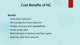
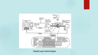
The document provides an overview of CNC (computer numerical control) machining compared to conventional machining. Some key points include:
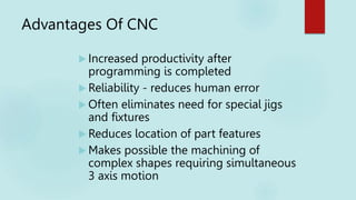
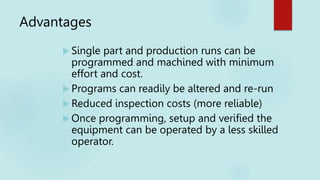
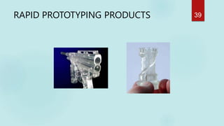
- CNC machines can precisely reproduce a programmed design and produce thousands of identical parts much faster than conventional machining.
- CNC machines can operate continuously without rest, and programming can be easily updated by changing software.
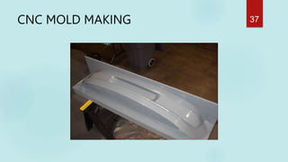
- Advanced CNC software allows for machining of complex geometries not possible through manual machining.
- CNC machines require less skilled operators than conventional machining once programmed.