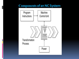
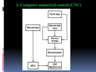
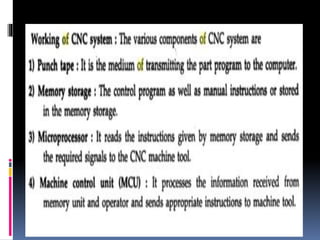
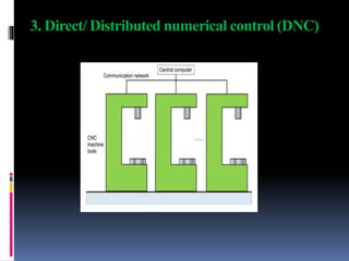
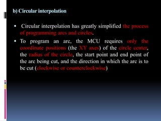
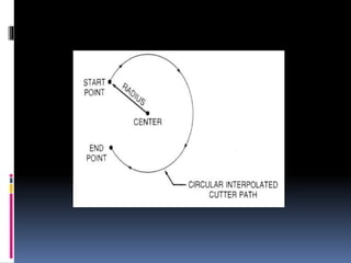
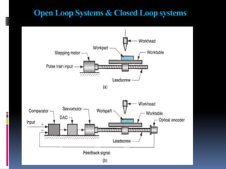
This document provides information about CNC (Computer Numerical Control) machines. It discusses:
- The components of a numerical control (NC) system, including the part program, machine control unit, and processing equipment.
- The differences between traditional NC, CNC, and DNC machines. CNC machines have their own onboard computers while DNC machines are networked.
- Types of motion control systems like point-to-point positioning and continuous path/contouring. Interpolation methods including linear and circular are described.
- Open loop and closed loop control systems. Closed loop provides feedback to check if commanded positions are achieved.
Numerical Control (NC) machine tools – CNC types, constructional details, special features, machining centre, and part programming fundamentals CNC – manual part programming – micromachining – wafer machining
This describes the mechanism of Computer Numerical Control along with its types, control system, motion system, Programming of CNC, G codes, Part programming, adaptive control machining etc.
CNC Programming for Begainer.
1.Easy Mehtod.
2.Complete Theoritical Knowledge.
3.Motion and coordinate system for NC machine.
4.Axes convention of VMC & HMC.
5.How to make Part Programming.
6.Coordinates System.
7.Programming Format.
8.List of G Codes And M Codes.
9.How to Use of Above Codes In Programme.
10.Reference Point and Return of Machine.
Modern Machine Tools:
CNC machines: Introduction, principles of operation,
Types – Vertical machining centres and horizontal machining centres,
major elements, functions, applications,
controllers,
open loop and closed loop systems
Types of automatic machines,
Transfer machines
Geometric modeling: Wire frame, surface and solid modeling - Engineering analysis;
design review and evaluation, automated drafting.
Numerical control: Need - advantages and disadvantages – classifications – Point to
point, straight cut and contouring positioning - incremental and absolute systems – open
loop and closed loop systems – DDA integrator and Interpolators – resolution – CNC and
DNC.
Programmable Logic Controllers (PLC): need – relays - logic ladder program –
timers, simple problems only - Devices in N.C. systems: Driving devices - feed
back devices: encoders, moire fringes, digitizer, resolver, inductosyn, and
tachometer.
Industrial Training at Shahjalal Fertilizer Company Limited (SFCL)MdTanvirMahtab2
This presentation is about the working procedure of Shahjalal Fertilizer Company Limited (SFCL). A Govt. owned Company of Bangladesh Chemical Industries Corporation under Ministry of Industries.
Welcome to WIPAC Monthly the magazine brought to you by the LinkedIn Group Water Industry Process Automation & Control.
In this month's edition, along with this month's industry news to celebrate the 13 years since the group was created we have articles including
A case study of the used of Advanced Process Control at the Wastewater Treatment works at Lleida in Spain
A look back on an article on smart wastewater networks in order to see how the industry has measured up in the interim around the adoption of Digital Transformation in the Water Industry.
Forklift Classes Overview by Intella PartsIntella Parts
Discover the different forklift classes and their specific applications. Learn how to choose the right forklift for your needs to ensure safety, efficiency, and compliance in your operations.
For more technical information, visit our website https://intellaparts.com
Student information management system project report ii.pdfKamal Acharya
Our project explains about the student management. This project mainly explains the various actions related to student details. This project shows some ease in adding, editing and deleting the student details. It also provides a less time consuming process for viewing, adding, editing and deleting the marks of the students.
About
Indigenized remote control interface card suitable for MAFI system CCR equipment. Compatible for IDM8000 CCR. Backplane mounted serial and TCP/Ethernet communication module for CCR remote access. IDM 8000 CCR remote control on serial and TCP protocol.
• Remote control: Parallel or serial interface.
• Compatible with MAFI CCR system.
• Compatible with IDM8000 CCR.
• Compatible with Backplane mount serial communication.
• Compatible with commercial and Defence aviation CCR system.
• Remote control system for accessing CCR and allied system over serial or TCP.
• Indigenized local Support/presence in India.
• Easy in configuration using DIP switches.
Technical Specifications
Indigenized remote control interface card suitable for MAFI system CCR equipment. Compatible for IDM8000 CCR. Backplane mounted serial and TCP/Ethernet communication module for CCR remote access. IDM 8000 CCR remote control on serial and TCP protocol.
Key Features
Indigenized remote control interface card suitable for MAFI system CCR equipment. Compatible for IDM8000 CCR. Backplane mounted serial and TCP/Ethernet communication module for CCR remote access. IDM 8000 CCR remote control on serial and TCP protocol.
• Remote control: Parallel or serial interface
• Compatible with MAFI CCR system
• Copatiable with IDM8000 CCR
• Compatible with Backplane mount serial communication.
• Compatible with commercial and Defence aviation CCR system.
• Remote control system for accessing CCR and allied system over serial or TCP.
• Indigenized local Support/presence in India.
Application
• Remote control: Parallel or serial interface.
• Compatible with MAFI CCR system.
• Compatible with IDM8000 CCR.
• Compatible with Backplane mount serial communication.
• Compatible with commercial and Defence aviation CCR system.
• Remote control system for accessing CCR and allied system over serial or TCP.
• Indigenized local Support/presence in India.
• Easy in configuration using DIP switches.
HEAP SORT ILLUSTRATED WITH HEAPIFY, BUILD HEAP FOR DYNAMIC ARRAYS.
Heap sort is a comparison-based sorting technique based on Binary Heap data structure. It is similar to the selection sort where we first find the minimum element and place the minimum element at the beginning. Repeat the same process for the remaining elements.
Hierarchical Digital Twin of a Naval Power SystemKerry Sado
A hierarchical digital twin of a Naval DC power system has been developed and experimentally verified. Similar to other state-of-the-art digital twins, this technology creates a digital replica of the physical system executed in real-time or faster, which can modify hardware controls. However, its advantage stems from distributing computational efforts by utilizing a hierarchical structure composed of lower-level digital twin blocks and a higher-level system digital twin. Each digital twin block is associated with a physical subsystem of the hardware and communicates with a singular system digital twin, which creates a system-level response. By extracting information from each level of the hierarchy, power system controls of the hardware were reconfigured autonomously. This hierarchical digital twin development offers several advantages over other digital twins, particularly in the field of naval power systems. The hierarchical structure allows for greater computational efficiency and scalability while the ability to autonomously reconfigure hardware controls offers increased flexibility and responsiveness. The hierarchical decomposition and models utilized were well aligned with the physical twin, as indicated by the maximum deviations between the developed digital twin hierarchy and the hardware.
We have compiled the most important slides from each speaker's presentation. This year’s compilation, available for free, captures the key insights and contributions shared during the DfMAy 2024 conference.
Overview of the fundamental roles in Hydropower generation and the components involved in wider Electrical Engineering.
This paper presents the design and construction of hydroelectric dams from the hydrologist’s survey of the valley before construction, all aspects and involved disciplines, fluid dynamics, structural engineering, generation and mains frequency regulation to the very transmission of power through the network in the United Kingdom.
Author: Robbie Edward Sayers
Collaborators and co editors: Charlie Sims and Connor Healey.
(C) 2024 Robbie E. Sayers
Saudi Arabia stands as a titan in the global energy landscape, renowned for its abundant oil and gas resources. It's the largest exporter of petroleum and holds some of the world's most significant reserves. Let's delve into the top 10 oil and gas projects shaping Saudi Arabia's energy future in 2024.
Immunizing Image Classifiers Against Localized Adversary Attacksgerogepatton
This paper addresses the vulnerability of deep learning models, particularly convolutional neural networks
(CNN)s, to adversarial attacks and presents a proactive training technique designed to counter them. We
introduce a novel volumization algorithm, which transforms 2D images into 3D volumetric representations.
When combined with 3D convolution and deep curriculum learning optimization (CLO), itsignificantly improves
the immunity of models against localized universal attacks by up to 40%. We evaluate our proposed approach
using contemporary CNN architectures and the modified Canadian Institute for Advanced Research (CIFAR-10
and CIFAR-100) and ImageNet Large Scale Visual Recognition Challenge (ILSVRC12) datasets, showcasing
accuracy improvements over previous techniques. The results indicate that the combination of the volumetric
input and curriculum learning holds significant promise for mitigating adversarial attacks without necessitating
adversary training.
4. Numerical control (NC)
Numerical control (NC) is a form of programmable automation in which
the mechanical actions of a machine tool are precisely controlled by means
of an programme of instructions.
NC is applied to a wide variety of manufacturing processes such as
machine tools (e.g. drilling, milling, turning, bending, punching, etc.), and
non-machine tool applications such as assembly, adhesive bonding and
inspection.
5. NC machining can be divided in to three types:
1. Traditional numerical control (NC) where mechanical
actions of a machine tool are precisely controlled by means of an
programme of instructions.
2. Computer numerical control (CNC) where each machine has
it own computer.
3. Direct numerical control (DNC) where a number of machines
are served by one computer
6. Components of an NC System
A Numerical control system consists of three basic
components:
1. Part Program
2. Machine Control Unit
3. Processing Equipment
9. The program of instructions or part program consists
of a detailed set of commands to be followed by the
processing equipment through actuators and sensors.
Each command specifies a position or motion that is to be
accomplished by the work head relative to the workpiece.
A position is defined by its x-y-z coordinates.
Typical instructions include spindle speed, spindle
direction, feed rate, tool selection, and other commands
related to the operation.
1. Part Program
10. Part programs are typically stored on
computers and sent directly to the machine
controller over a communications cable.
The part program is prepared by a part
programmer, a person who is familiar with the
details of the programming language and also
understands the technology of the processing
equipment.
11. 2.Machine Control Unit (MCU)
The machine control unit (MCU) converts the part
program into a usable format and executes it in the form of
the mechanical actions of the processing equipment.
The MCU consists of both hardware and software.
The hardware includes the microcomputer, components to
interface with the processing equipment, and certain
feedback control elements.
12. The software in the MCU includes control system
software, calculation algorithms, and translation
software to convert the NC part program into a usable
format for the MCU.
The MCU also permits the part program to be edited in
case the program contains errors, or changes in cutting
conditions are required.
13. 3.Processing Equipment
The processing equipment accomplishes the sequence
of processing steps to transform the starting work
piece/part into a completed part.
It operates under the control of the MCU according to
the instructions in the part program
14. Advantages
Increased productivity
Greater manufacturing
flexibility
Improved accuracy
Reliable and Safe operation
Shorter cycle times
lower manufacturing lead
times,
Reduced nonproductive time
Reduced human error
Machining of complex 3-D
shapes
Multi-operational machining
15. Disadvantages
High initial investment
High maintenance cost
Need skilled Part programmer
Not cost effective for low production cost
Applications
Machine tools applications (e.g. drilling, milling,
turning, bending, punching, etc.)
Non-machine tool applications (e.g. assembly, adhesive
bonding and inspection.
19. Classifications of NC Machine
1. Motion control : Point to point (PTP), or
Positioning ,Continuous or contouring Interpolation
2. Control loops : Open loop and
Closed loop
3. Positioning systems : Incremental and
Absolute positioning
4. Power drives : Hydraulic,
Electric,or Pneumatic
20. Types of coordinate/Positioning system
There are two types of coordinate system they are:
1. Absolute coordinate system
2. Incremental coordinate system
1. Absolute coordinate system
Absolute program locations are always given from a single
fixed zero or origin point.
The zero or origin point may be a position on the machine
table, such as the corner of the worktable or at any specific
point on the work piece.
In absolute dimensioning/programming, each point or
location on the work piece is given as a certain distance from
the zero or reference point.
22. 2. Incremental coordinate system
In incremental system, the work coordinates change because
each location is the zero point for the move to the next
location.
Last Point is considered as origin point for next
point/location.
Incremental program locations are always given as the
distance and direction from the immediately preceding
point.
23. Types of positioning system
There are two types of positioning system. they are:
1. Point to point/ Positioning
2. Continuous/ Contouring
3. Interpolation
1. Point to point
Point-to-point positioning is used when it is necessary to
accurately locate the spindle, or the work piece mounted on
the machine table, at one or more specific Locations to
perform such operations as drilling, reaming, boring, tapping,
and punching.
24. 1. Pointto Point
• Moving at maximum rate from point to point.
• Accuracy of the destination is important but
not the path.
• Drilling is a good application.
25. Point-to-point positioning is the process of positioning from
one coordinate (XY) position or location to another,
performing the machining operation, and continuing this
pattern until all the operations have been completed at all
programmed locations.
In the above fig. point 1 to point 2 is a straight line, and the
machine moves only along the X axis; but points 2 and 3
require that motion along both the X and Y axes takes place.
As the distance in the X direction is greater than in the Y
direction, Y will reach its position first, leaving X to travel in
a straight line for the remaining distance. A similar motion
takes place between points 3 and 4
26. 2. Continuous Path
• Controls both the
displacement and the
velocity.
• Machining profiles.
• Precise control.
27. Contouring, or continuous path machining, involves
work that produced on a lathe or milling machine,
where the cutting tool is in contact with the workpiece as
it travels from one point to the next.
Continuous path positioning is the ability to control
motions on two or more machine axes simultaneously to
keep a constant cutter-workpiece relationship.
All axes of motion might move simultaneously, each at a
different velocity.
The programmed information in the CNC program must
accurately position the cutting tool from one point to the
next and follow a predefined accurate path at a
programmed feed rate in order to produce the form or
contour required
28. 3. Interpolation
The method by which contouring machine tools move
from one programmed point to the next is called
interpolation.
This ability to merge individual axis points into a
predefined tool path is built into most of today’s MCUs.
There are five methods of interpolation: linear, circular,
helical, parabolic, and cubic.
All contouring controls provide linear interpolation, and
most controls are capable of both linear and circular
interpolation.
Helical, parabolic, and cubic interpolation are used by
industries that manufacture parts which have complex
shapes, such as aerospace parts and dies for carbodies
29. a) LinearInterpolation
Linear Interpolation consists of any programmed points
linked together by straight lines, whether the points are
close together or far apart.
Curves can be produced with linear interpolation by
breaking them into short, straight-line segments.
This method has limitations, because a very large
number of points would have to be programmed to
describe the curve in order to produce a contour shape.
A contour programmed in linear interpolation requires
the coordinate positions (XY positions in two-axis work)
for the start and finish of each line segment.
30.
31. b) Circular interpolation
Circular interpolation has greatly simplified the process
of programming arcs and circles.
To program an arc, the MCU requires only the
coordinate positions (the XY axes) of the circle center,
the radius of the circle, the start point and end point of
the arc being cut, and the direction in which the arc is to
be cut (clockwise or counterclockwise)
32.
33. Types of Motion control system
There are two types of control systems. They are:
1. Open Loop Systems
2. Closed Loop systems
35. 1. Open Loop Systems
The term open-loop means that there is no feedback.
In open loop systems the motion controller produces
outputs depending only on its set points, without
feedback information about the effect that the output
produces on the motion axes.
In open loop systems, the set points are computed from
the instructions in the Part program and fed to the
controller, which may reside in a different
microprocessor, through an interface.
These motion commands may be in the form of electrical
pulses (typical for step motor drives) or analog or digital
signals, and converted to speed or current set points by
the controller.
36. These set points, in turn, are sent to the power electronic
drive system that applies the necessary voltage/current to
the motors.
The primary drawback of open-loop system is that there
is no feedback system to check whether the commanded
position and velocity has been achieved.
If the system performance is affected by load,
temperature or friction then the actual output could
deviate from the desired out.
37. 2. Closed Loop systems
Closed-loop control, continuously senses the actual position
and velocity of the axis, using digital sensors such as
encoders or analog sensors such resolvers and tacho
generators and compares them with the set points.
The difference between the actual value of the variable and
its set point is the error. The control law takes the error as
the input and drives the actuator, in this case the servo
motor and its drive system, to achieve motion variables that
are close to the set points
38. Closed loop systems can achieve much closer tracking of
set points even with disturbances and parameter variations
in the system with with temperature.
Closed-looped systems, on the other hand, require more
complex control as well as feedback devices and circuitry in
order for them to implement both position and velocity
control.
Most modern closed-loop CNC systems are able to provide
very close resolution of 0.0001 of an inch.
39. Coordinates/axis on a Lathe
Most lathes are programmed on two axes.
The X axis controls the cross motion of the cutting
tool.
Negative X (X-) moves the tool towards the spindle
centerline; positive X moves the tool away from the
spindle centerline.
The Z axis controls the carriage travel toward or
away from the headstock
40. The directions of movement in a machine tool are based
on a co-ordinate system allocated to the axes of motion
of the slides.
As in the conventional lathe there is movement of slides
in two directions along two axes,
one axis being parallel to the spindle axis and the other
axis perpendicular to the spindle axis.
The axis parallel to the spindle axis is called Z-axis.
The axis perpendicular to the spindle axis is called X-
axis.
Since the machine co-ordinate system has two axes, X
and Z, it is referred to as the X-Z co-ordinate system.
46. The milling machine can be programmed on three axes:
The X axis controls the table movement left or right.
The Y axis controls the table movement toward or
away from the column.
The Z axis controls the vertical (up or down)
movement of the knee or spindle.
47.
48. Reference/Origin Points
Three reference points are either set by manufacturer or
user.
1) Machine Origin
2) Program Origin
3) Part Origin
1) Machine Origin
The machine origin is a fixed point set by the machine tool
builder. Usually it cannot be changed. Any tool movement
is measured from this point. The controller always
remembers tool distance from the machine origin.
51. 2) Program Origin
It is also called home position of the tool. Program origin is
point from where the tool starts for its motion while executing a
program and returns back at the end of the cycle.
This can be any point within the workspace of the tool which is
sufficiently away from the part. In case of CNC lathe it is a
point where tool change is carried out.
3) Part Origin
The part origin can be set at any point inside the machine's
electronic grid system. Establishing the part origin is also
known as zero shift, work shift, floating zero or datum. Usually
part origin needs to be defined for each new setup.
Zero shifting allows the relocation of the part. Sometimes the
part accuracy is affected by the location of the part origin.
52. Part Program
A part program is a set of instructions given to a
computerized numerical control (CNC) machine to
control its operation.
Numerical control (NC) information is generally
programmed in blocks of codes/words.
Each word conforms to the EIA standards and they are
written on a horizontal line
54. A program is made up a number of blocks. Similarly a
block is made up a number of words.
A word consists of an address character and a string of
digits (alphanumeric character).
Each code conforms to EIA (Electronic Industries
Association) standards, are in a logical sequence called a
block of information.
Each block should contain enough information to
perform one machining operation.
Each block is separated by a semicolon(;) or End of the
block (EOB).
55. Types of NC codes
1. G-codes/Preparatory codes
Preparatory functions are used to specify the control
mode of the operation.
G-codes are always programmed at the start of the block.
The term "preparatory" in NC means that it "prepares"
the control system to be ready for implementing the
information that follows in the next block of
instructions.
G-codes describe the type of machine movement, type of
interpolation, type of dimensioning, time related
functions and activate certain operating conditions
within the control.
56. The action of G codes is either modal or block by block.
G codes once programmed, remain active until another
G code of the same group is programmed, after which
the previous one gets cancelled, are said to be MODAL.
G code which remains active only in the block in which
it is programmed, is said to be BLOCKWISE ACTIVE
or ONE SHOT G CODE.
57.
58.
59. 2. M-codes/Miscellaneous codes
Miscellaneous functions use to perform a group of
instructions such as coolant on/off, spindle on/off, tool
change, program stop, or program end.
M-codes are often referred to as machine functions or M-
functions.