Downloaded 105 times


![HARDWARE REQUIREMENT
Components
ATMega32 µC / 8051 µC
MC13202 (2.4 GHz Low Power Transceiver
for the IEEE® 802.15.4 Standard) X 2
[ZIGBEE Supported]
Suitable Antenna (iBall 2.4 Ghz Wireless
Antenna) X2
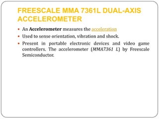
MMA7361L: 3-Axis Analog Output
Acceleration Sensor
IR sensor (From T.E. Project)
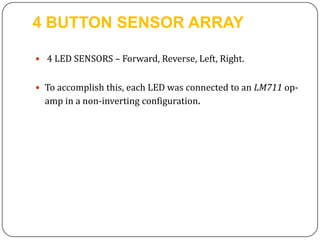
LEDs for SENSOR ARRAY
Other](https://image.slidesharecdn.com/seminar1-130922053129-phpapp02/85/Accelerometer-and-LED-Sensor-Array-Based-Remote-Control-Car-13-320.jpg)


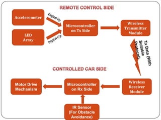
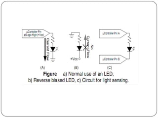
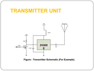
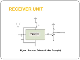
This document outlines a final year project to develop a remotely controlled car using an accelerometer and LED array for control inputs. The car will be controlled wirelessly using a dual-axis accelerometer tilt sensor and custom LED array detected by a microcontroller on both the transmitter and receiver ends connected by a ZigBee wireless module. The project aims to develop new control mechanisms using these sensors and wireless transmission to remotely operate the car for applications in robotics, military, search and rescue, and recreation.


![Getting Started with Apache Spark: Big Data Made Simple [Free Meetup]](https://cdn.slidesharecdn.com/ss_thumbnails/apachesparkgettingstarted-260203175547-8361bcc3-thumbnail.jpg?width=640&height=640&fit=bounds)


