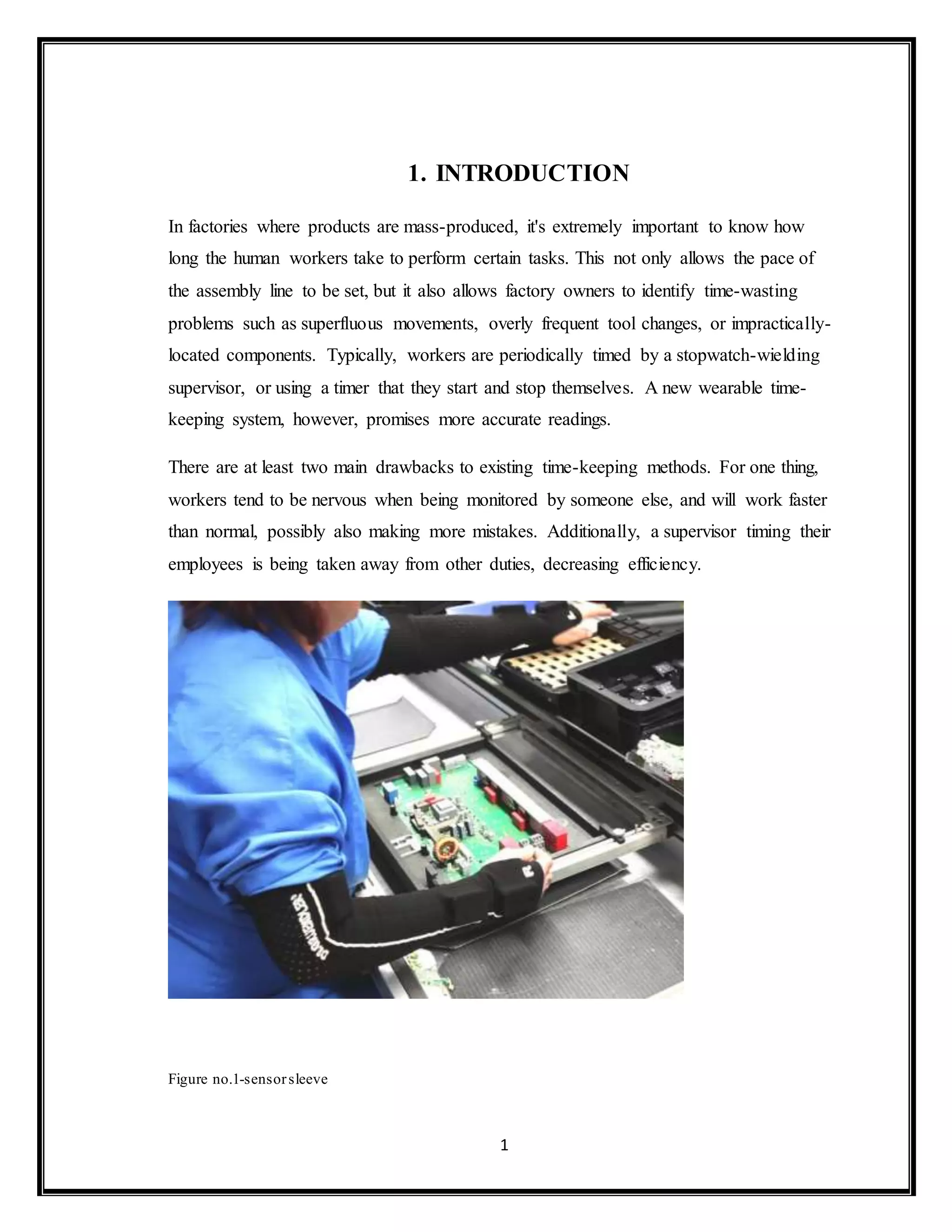
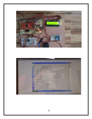
The document describes a new wearable time-keeping system developed by Fraunhofer to more accurately measure the time taken by workers to perform tasks in factories. Existing stopwatch methods can only monitor a few workers and make them nervous. The new system uses sensor-equipped sleeves to record workers' arm movements without supervision needed. Data from the sleeves is analyzed to identify inefficient motions and optimize processes. The system aims to maximize efficiency while acknowledging workers may occasionally need breaks.
International Journal of Engineering Research and Applications (IJERA) is an open access online peer reviewed international journal that publishes research and review articles in the fields of Computer Science, Neural Networks, Electrical Engineering, Software Engineering, Information Technology, Mechanical Engineering, Chemical Engineering, Plastic Engineering, Food Technology, Textile Engineering, Nano Technology & science, Power Electronics, Electronics & Communication Engineering, Computational mathematics, Image processing, Civil Engineering, Structural Engineering, Environmental Engineering, VLSI Testing & Low Power VLSI Design etc.
The important aspect of our project revolves around the concept of monitoring the machines utilized in the textile industry. It is aimed at continuously examining the components and machineries in the industry. This project have the ability to establish communication link between various machineries in industries and the controlling system. It also helps in sequential power ON and power OFF of the machineries depending on the outputs received from the controlling unit. The project enables automatic manipulation of the machineries. The controlling system monitors various parameters of the machineries and evaluates its performance and updates the required changes. The machineries will be linked via RF transmitter and receiver. This enables communication link between the controlling device and the connected recipient devices. For maintenance purposes both automatic and manual methods of manipulation are provided. Either of them can be chosen depending upon the purpose. When automatic mode is turned on the machines can be controlled only by the server.
The paper presents an Arduino-based wireless sensor network to monitor parking lots using a non-standard low-power energy-balanced system. The event-driven routing protocol follows the hierarchical clustering philosophy. Energy is saved by minimising the number of transmissions needed to forward information to the base station. The smart sensor platform is build using the popular Arduino development platform, Sharp IR distance sensors and nRF24 low-power radio modules. Our practical results show that this platform is easy to use, but not the most appropriate platform to develop low-power wireless sensor network applications.
One of the leading branches of engineering, Instrumentation engineering deals in mechanics and operation of measuring instruments. This type of engineering has a major role in the industries which have automated processes. For example, chemical and manufacturing industries. The role of engineers in this field is to ensure stability, reliability, safety, and enhanced productivity.
Instrumentation engineering covers various topics and subjects from other branches of engineering, which makes it a different course in the field of engineering. Students who prefer to study diverse subjects should opt for this branch of engineering. Ekeeda offers Online Instrumentation Engineering Courses for all the Subjects as per the Syllabus.
International Journal of Computational Engineering Research (IJCER) is dedicated to protecting personal information and will make every reasonable effort to handle collected information appropriately. All information collected, as well as related requests, will be handled as carefully and efficiently as possible in accordance with IJCER standards for integrity and objectivity.
Biomedical Parameter Transfer Using Wireless Communicationijsrd.com
In spite of the improvement of communication link and despite all progress in advanced communication technologies, there are still very few functioning commercial wireless monitoring systems, which are most off-line, and there are still a number of issues to deal with. Therefore, there is a strong need for investigating the possibility of design and implementation of an interactive real-time wireless communication system. In this paper, a generic real-time wireless communication system was designed and developed for short and long term remote patient-monitoring applying wireless protocol. The primary function of this system is to monitor the temperature and Heart Beat of the Patient and the Data collected by the sensors are sent to the Microcontroller. The Microcontroller transmits the data over the air. At the receiving end a receiver is used to receive the data and it is decoded and fed to Microcontroller, which is then displayed over the LCD display. If there is a dangerous change in patient's status an alarm is also sounded. The paper deals with the design and development of hardware and software for temperature and heartbeat measurement of a patient over LCD.
A Review on Zigbee, Gsm and Wsn Based Home Security by Using Embedded Control...ijesajournal
Embedded controlled detector network is that the technology needs to implement environmental solutions
effectively. The wireless sensor network is used to control respective devices and monitor environmental
parameters effectively. Wireless sensor network technology is used to monitor environmental parameters
such temperature sound pressure in many applications. Many researchers are developed the wireless
sensor network to implement real time surveillance for many applications. The existing wired systems are
bulky, very high cost and difficult to maintain. The proposed system is user friendly, low cost and
controlled by embedded controlled sensor network. In the proposed system ARM based microcontroller is
used for monitoring and wireless sensors are used to control the various devices.
Small, widely available and dirt-cheap ultrasonic sensors enable us to design both simple and lavish measuring devices for all kinds of ranging. Take one of these modules, add a display, a couple of press-buttons and a micro-controller loaded with software, and you now have all the ingredients for a circuit of this kind.
K30 controller is intended for permanent installation, for
indoor use only, in an electrical panel which encloses the
rear housing, exposed terminals and wiring on the back.
This paper focuses on the materials, working principle of a robotic vehicle which will be controlled with hand motion. The aim of this research is to enhance industrialization by creating a hand motion controlled robotic vehicle, since it uses hand motion it will be easier to use in automation and various industries. It is also very beneficial for people with disabilities since only hand motion is required. There were various materials that were used in the research. 2 microcontrollers, an accelerometer, RF modules, encoder, decoder, diode, motor driver IC, DC motor and batteries. The microcontrollers are small computers which can be programmed to be utilized in various different ways. The Accelerometer is a PCB or a sensor which detects speed. The RF modules are of two types which are transmitters and receivers and they are components which are used to send data and information wirelessly. The encoder and decoder are used to convert the binary to any n number of output terminals. The diode is used to send the electricity in one direction. The motor driver IC controls the DC motor from the information given by the microcontroller ICs and lastly a 9v Battery will be used to power the system. The arduino software will be used to program the IC so it can perform the required task. The gadget features a receiver circuit that is intended to be worn on top of the user's glove. The vehicle's circuit incorporates an RF receiver, an 8051 CPU, and a Driver IC to power the motors. This method is extremely useful for persons with impairments since it allows a robotic vehicle to drive itself using hand gestures. The person only needs to move his hand to move the car forward, backward, left, or right. As a result, the user is not required to push any buttons.
International Journal of Engineering Research and Applications (IJERA) is an open access online peer reviewed international journal that publishes research and review articles in the fields of Computer Science, Neural Networks, Electrical Engineering, Software Engineering, Information Technology, Mechanical Engineering, Chemical Engineering, Plastic Engineering, Food Technology, Textile Engineering, Nano Technology & science, Power Electronics, Electronics & Communication Engineering, Computational mathematics, Image processing, Civil Engineering, Structural Engineering, Environmental Engineering, VLSI Testing & Low Power VLSI Design etc.
ARM based System for Monitoring Grain ConditionAM Publications
Agriculture is the backbone of any nation’s economy and there is a dependency between agricultural growth and economic prosperity. As India is an Agriculture country where 70% of the population depends on farming, the storage of grains plays a crucial role in national economy. Due to the seasonality of grain production, the storage of grain is the top priority task for restoring and reusing. In the process of grain storage, temperature, humidity and carbon dioxide concentration (CO2) are major ecological factors that can influence directly on the quality of the Grain. Hence, there is a necessity to monitor the vital parameters continuously during storage and communicate the status to the manger in real time which becomes a challenging. The traditional methods are limited to simple manual temperature and humidity testing which are relatively backward since grain situation analysis are made without any effective means of processing and regulation hence there is a need for smart grain management system with automation which can also avoid hidden security risks. The Real-time monitoring of the grain storage system is designed based on ARM7 and using GSM module as lower level Control unit which improves the level of grains storage and reduce the grain losses during storage procedure and also reduce man power and labor intensity.
International Journal of Engineering Research and Applications (IJERA) is an open access online peer reviewed international journal that publishes research and review articles in the fields of Computer Science, Neural Networks, Electrical Engineering, Software Engineering, Information Technology, Mechanical Engineering, Chemical Engineering, Plastic Engineering, Food Technology, Textile Engineering, Nano Technology & science, Power Electronics, Electronics & Communication Engineering, Computational mathematics, Image processing, Civil Engineering, Structural Engineering, Environmental Engineering, VLSI Testing & Low Power VLSI Design etc.
Ijeee 33-36-surveillance system for coal mines based on wireless sensor networkKumar Goud
Abstract: The foremost critical task for coal mine is of keeping track of miners spread out across a large mining areas .It becomes even difficult when mine tunnels collapse. Many mines use a radio system to track miners, but when a collapse occurs, the base stations connected by a thin wire often are rendered useless. In this project to overcome the demerits of radio system we used wireless technology for tracking the miners. For this purpose a small RF transmitter module is equipped to each person entering a mine. Each transceiver placed in the mine look after the location of miners. The transceivers communicate with base stations through Zigbee module. In addition of tracking the location of miners we also include sensors such as temperature & humidity to intimate the base station & miners when some atmosphere changes occur. Mine operators are now able to monitor the real-time locations of each miner to better pinpoint their locations in the event of an emergency. Even after a full-day of use, mine operators can locate an individual miner within ten feet.
Key Words: Wireless sensor networks (WSN), ZIGBEE, and LPC2148.
Wireless energy meter monitoring with automated tariff calculationUdayalakshmi JK
Electricity billing has become a difficult task. The board has to make regular visit to the consumers house to make the reading. Also it can cause manual error. Now here we are monitoring the energy meter with modern techniques. The total energy consumed by the consumer and the consumption cost is known to the consumer and to the board by means of a hand held device.
Design Efficient Wireless Monitoring Platform for Recycling Point SpotsIJMTST Journal
There is a growing demand for low cost, very low power and reduced size monitoring systems with
wireless communications, to be used in different kinds of industrial environments. In several countries waste
separation and recycling is a major issue. Consequently, the number of recycling spots has been steadily
increasing. In order to ensure that recycle bins are properly maintained, several monitoring solutions have
been proposed. These still have several limitations, such as requiring wires for power and/or communications
and not being able to fit in all existing types of bins. This paper presents WECO, a wireless embedded solution
for monitoring the level of the bins located in recycling spots. The proposed system automatically alerts a
remote central station when a bin reaches a programmable filling level, thus avoiding the need to spot check
if the bin is full and ensuring that the recycling spot is kept clean. The developed prototype required
hardware-software co-design and aimed to meet the above mentioned requirements, resorting to the IEEE
802.15.4 protocol for wireless communications between all nodes in the network, each based on a
System-On-Chip CC2530 from Texas Instruments. Due to its wireless nature, the architecture requires a
battery for power supplying the nodes, with a life time of at least six years. The filling level readings of each
bin in a recycling spot are made using an ultrasonic sensor. The data collected by the monitoring platform is
then sent to the remote central station that processes it in order to optimize routes and establish a scheduled
collection of the recycling spots.
The peer-reviewed International Journal of Engineering Inventions (IJEI) is started with a mission to encourage contribution to research in Science and Technology. Encourage and motivate researchers in challenging areas of Sciences and Technology.
https://technoelectronics44.blogspot.com/
ULTRASONIC SENSOR RANGE FIND OUT, it has Implemented by using ULTRASONIC SENSOR, 8051 microcontrollers, LCD display, and a sound indicator.
Handicapped Assistance Device for Controlling Electrical Appliances Jamuna R - Assistant Professor,
Abhinai S - UG scholar,
Jhananadhan SP - UG scholar,
Department of ECE,
SNS College of Engineering, Coimbatore, India
Health Monitoring System of Elderly using Wireless Sensor NetworkIjcatr04031005Editor IJCATR
Wireless-sensor-network-based home monitoring system for elderly activity behaviour involves functional assessment of daily activities. In this paper, we report a mechanism for estimation of elderly well-being condition based on usage of house-hold appliances connected through various sensing units. We define a two new wellness functions to determine the status of the elderly on performing essential daily activities. The modernized system for monitoring and evaluating the essential daily activities was tested at homes for four different elderly persons living alone and the results are encouraging in determining wellness of the elderly.
Health Monitoring System of Elderly using Wireless Sensor NetworkIjcatr04031005
version1
1. 1
1. INTRODUCTION
In factories where products are mass-produced, it's extremely important to know how
long the human workers take to perform certain tasks. This not only allows the pace of
the assembly line to be set, but it also allows factory owners to identify time-wasting
problems such as superfluous movements, overly frequent tool changes, or impractically-
located components. Typically, workers are periodically timed by a stopwatch-wielding
supervisor, or using a timer that they start and stop themselves. A new wearable time-
keeping system, however, promises more accurate readings.
There are at least two main drawbacks to existing time-keeping methods. For one thing,
workers tend to be nervous when being monitored by someone else, and will work faster
than normal, possibly also making more mistakes. Additionally, a supervisor timing their
employees is being taken away from other duties, decreasing efficiency.
Figure no.1-sensorsleeve
2. 2
2. LITERARY SURVEY
In an attempt to further narrow the gap between man and machine,
German tech company Fraunhofer has created a device that will measure the
movements of industrial workers down to the second.
Industrial manufacturers can use the device, a sleeve equipped with tiny sensors,
to analyze each individual movement during assembly and ensure that not a
moment is wasted. With data from sleeve movements, manufacturers should be
able to minimize “impractically located components” or “overly frequent tool
changes.” In other words, with a few tweaks to the manufacturing process,
workers can essentially become well-oiled machines.
“The present stopwatch method only allows a process organizer to time five
individuals simultaneously, depending on the situation,” said Martin Woitag,
research manager at the Fraunhofer IFF in a press release. “Our solution makes it
possible to record time simultaneously, even at several workplaces, without
requiring additional labor. The system’s greater precision and objectivity is
crucial.” Inside the sleeve are three matchbox-sized sensors, each designed to
record hand and arm movements from start to finish. Actions such as reaching,
grasping, joining and releasing can all be differentiated.
Once the manual labor is done, a PC application completes the process by
calculating and reconstructing motion sequences based on the sensor data from
the sleeve. Each process is then broken down into segments and relative time is
established, allowing researchers to shave off the more superfluous of motions
from workers’ routines.
Pinpointing workers’ exact movements may be a crucial step in maximizing
efficiency, but it could also be seen as a burden for employees who simply need a
break every now and then. Wasted seconds, like cotton mills and mule-drawn
plows, may simply be a thing of the past.
At present, the sleeves can be used for assembly jobs at sitting workplaces in
logistics and manufacturing. In the next stage, the researchers in Magdeburg
3. 3
intend to configure the system to also analyze assembly operations during which
workers stand or move around. They additionally plan to use the sensors to detect
posture and thus analyze workplace ergonomics.
5. 5
ACCELEROMETER:
An accelerometer is an electromechanical device that will measure acceleration
forces. These forces may be static, like the constant force of gravity pulling at your feet,
or they could be dynamic - caused by moving or vibrating the accelerometer.
Accelerometers use the piezoelectric effect - they contain microscopic crystal structures
that get stressed by accelerative forces, which causes a voltage to be generated. Another
way to do it is by sensing changes in capacitance. If you have two microstructures next to
each other, they have a certain capacitance between them. If an accelerative force moves
one of the structures, then the capacitance will change. The capacitance is then converted
into voltage.
The three axis accelerometer are basically used to identify the movements across the
three axis i.e. x-axis, y-axis, z-axis. Accelerometer is an electronic device which is
interfaced using I2C protocol and provides the reading after every 1msec. According to
the requirement of the application, the microcontroller will take the reading from the
accelerometer within a fixed interval of time and do the necessary operation according to
the requirement of the application
IR OBSTACLE SENSOR:
Here we are connecting an IR based obstacle sensor. The 50 ohm resister is used for
current limiting. The current through the LED is 5v / 50 ohm = 100 mA, which is high
for an LED. But to increase the range of the obstacle sensor we are using a lower range
resistor (50 ohm). On the receiver side we have connected the IR receiver in reverse bias.
So as soon as the light falls in the IR receiver, the anode voltage increases and when the
anode voltage is more than the cathode voltage then the LED is in forward bias mode and
start conducting.
6. 6
PULSE RATE SENSOR:
The pulse rate sensor interfaced within the system will keep on monitoring the pulses of
the worker in order to ensure that the worker is in good health. If the pulse rate of the
worker is fast then it will indicate that the worker is stressed and needs to be given a
break. So on the basis of the output provided by the pulse rate sensor, we can track the
health issues of the worker.
RF Tx-Rx (ZIGBEE):
Zigbee is the result of the demand from industry and consumer for wireless applications
that demand for lower data rate, longer battery life, simple design, shorter range and low
cost solutions.
Introduction to IEEE 802.15.4
IEEE 802.15.4 is a simple standard that specifies the media access controller (mac) and
physical (phy) networking layers for packet data protocol. Its license free frequency
bands are: 2.4Ghz(16 channels with baud rate of 250 kps)
902 mhz - 928 mhz (10 channels with baud rate of 40 kps) 868 mhz - 870 mhz (1 channel
with baud rate of 20 kps)
North america, europe, australia and new zealand use the sub 1 ghz bands whereas the
rest of the world uses 2.4 ghz bands.
It uses carrier sense multiple access with collision avoidance for channel access. The
security method used is aes-128. Have message acknowledgement and a host of other
features.
7. 7
Zigbee applications
Zigbee technology is based on IEEE 802.15.4 industry standard. It incorporates the
standard, adding the logical network, security and software to it. It supports up to 3
network topologies namely star, mesh and cluster tree. Developers need only have to
focus on application while the MCU/microprocessor/RF transceiver makers and
Zigbeealliance take care of the RF transmitter, RF receiver, RF channel and its protocol.
There are 3 types of traffics that can be used.
A) Periodic data
An example of this traffic is a wireless sensor to read the water meter. The sensor is
programmed to wake up at certain interval to transmit the information needed and goes
back to sleep after this is done.
B) Intermittent data
An example of this traffic is a wireless light switch to on or off a light manually. It is
triggered only by external input and hence wakes up to transmit the message to the
network. When done, it is disconnected to the network and hence save energy.
C) Repetitive data
An example of this traffic is the security system monitoring. The devices are time
multiplex to return its status to the network. This type uses more energy.
There are numerous applications that can be implemented using zigbee. Amongst others
are in the industry and home applications.
In the industry, the applications include utility and metering where gas/water/electricity
meter readings are automated and send back to utility headquarter for further action. This
saves the time it takes for their personnel to come to the premises to take its reading. In
8. 8
the area of warehousing/inventory management, the wireless technology will enable
accurate and hassle free management of goods. Security and access control, building
management system and lighting control are among the applications that can be
implemented with ease. In the home, a total home automation system to control lightings,
blinds, air conditioning, security system, remote control and appliances can be
implemented. We are going to use ZIGBEE technology to control various electrical
appliances remotely.
9. 9
3.2 Hardware design and specifications
MICROCONTROLLER LPC 2138
16/32-bit ARM7TDMI-S microcontroller in a tiny LQFP64 or HVQFN package.
8/16/32 kB of on-chip static RAM and 32/64/128/256/512 kB of on-chip flash
program memory.
128-bit wide interface/accelerator enables high-speed 60 MHz operation.
In-System Programming/In-Application Programming (ISP/IAP) via on-chip
bootloader software.
Single flash sector or full chip erase in 400 ms and programming of 256 B in 1
millisecond.
Embedded ICE RT and Embedded Trace interfaces offer real-time debugging
with the On-chip Real Monitor software and high-speed tracing of instruction
execution.
8-channel 10-bit ADCs provide a total of up to 16 analog inputs, with conversion
times as low as 2.44 ms per channel.
Single 10-bit DAC provides variable analog output.
Two 32-bit timers/external event counters (with four capture and four compare
channels each), PWM unit (six outputs) and watchdog.
Low power Real-time clock with independent power and dedicated 32 kHz clock
input.
Multiple serial interfaces including two UARTs (16C550), two Fast I2C-bus (400
kbit/s),SPI and SSP with buffering and variable data length capabilities.
On-chip integrated oscillator operates with external crystal in range of 1 MHz to
30 MHz and with external oscillator up to 50 MHz.
Power saving modes include Idle and Power-down.
CPU operating voltage range of 3.0 V to 3.6 V (3.3 V ± 10 %) with 5 V tolerant
I/O pads.
10. 10
Figure no.3 LPC 213x
LCD :-
LAMPEX
16*2,BACKLIT FACILITY,
TRANSMISSION CHARACTERISTICS:
1> RS 232 PROTOCOL is used for serial communication in between MCS to
Zigbee.
And pc to Zigbee.
SOFTWARE
µC programming: Embedded C
11. 11
RESET DESIGN:
Figure no.4- Reset circuit
Reset is used for putting the microcontroller into a 'known' condition. That
practically means that microcontroller can behave rather inaccurately under certain
undesirable conditions. In order to continue its proper functioning it has to be reset,
meaning all Registers would be placed in a starting position. Reset is not only used when
microcontroller doesn't behave the way we want it to, but can also be used when trying
out a device as an interrupt in program execution, or to get a microcontroller ready when
loading a program.
In order to prevent from bringing a logical zero RESET pin accidentally, RESET
has to be connected via resistor to the positive supply pole AND a capacitor from RESET
to the ground. Resistor should be between 5 and 10K and the capacitor can be in between
1µf tp 10 µf. This kind of resistor capacitor combination, gives the RC time delay for the
µc to reset properly.
R4
10k
C7
10u
3.3V
1
2
3
4
5
6
7
8
9
10
11
12
13
14
15
16
17
18
19
20
22
21
23
24
25
26
27
28
29
30
31
32
33
34
35
36
37
38
39
40
41
42
43
44
45
46
47
48
49
50
51
52
53
54
55
56
57
58
59
60
61
62
63
64
XTAL1
XTAL2
P0.0/TxD0/PWM1
P0.1/RxD0/PWM3/EINT0
P0.2/SCL0/CAP0.0
P0.3/SDA0/MAT0..0/EINT1
P0.4/SCK0/CAP0.1/AD0.6
P0.5/MISO0/MAT0.1/AD0.7
P0.6/MOSI0/CAP0.2/AD1.0
P0.7/SSEL0/PWM2/EINT2
P0.8/TxD1/PWM4/AD1.1
P0.9/RxD1/PWM6/EINT3
P0.10/RTS1/CAP1.0/AD1.2
P0.11/CTS1/CAP1.1/SCL1
P0.12/DSR1/MAT1.0/AD1.3
P0.13/DTR1/MAT1.1/AD1.4
P0.14/DCD1/EINT1/SDA1
P0.15/RI1/EINT2/AD1.5
P0.16/EINT0/MAT0.2/CAP0.2
P0.17/CAP1.2/SCK1/MAT1.2
P0.18/CAP1.3/MISO1/MAT1.3
P0.19/MAT1.2/MOSI1/CAP1.2
P0.20/MAT1.3/SSEL1/EINT3
P0.21/PWM5/AD1.6/CAP1.3
P0.22/AD1.7/CAP0.0/MAT0.0
P0.23
P0.25/AD0.4/AOUT
P0.27/AD0.0/CAP0.1/MAT0.1
P0.28/AD0.1/CAP0.2/MAT0.2
P0.29/AD0.2/CAP0.3/MAT0.3
P0.30/AD0.3/EINT3/CAP0.0
V3
RST
VREF
VSS
VSSA
P1.16/TRACEPKT0
P1.17/TRACEPKT1
P1.18/TRACEPKT2
P1.19/TRACEPKT3
P1.20/TRACESYNC
P1.21/PIPESTAT0
P1.22/PIPESTAT1
P1.23/PIPESTAT2
P1.24/TRACECLK
P1.25/EXTIN0
P1.26/RTCK
P1.27/TDO
P1.28/TDI
P1.29/TCK
P1.30/TMS
P1.31/TRST
V3
V3
VSS
VSS
VSS
VSS
RTXC1
RTXC2
V3A
VBAT
P0.31
P0.26/AD0.5
U3
LPC2138_SQUARE
12. 12
As shown in the above circuit we are connecting an RC circuit to the RESET (pin 57) of
µC .The ARM µC has an active low reset, therefore we connect an RC circuit. As shown
the capacitor is initially at 0v.It charges via the supply through a 10 Kohm resistance in
series, therefore the reset time of our circuit is:
R*C = 10kohm * 0.1 µf = 1 msec
Recommended time of reset = 1 µsec
Here the RC time can vary from 10 µsec to 1 msec.
13. 13
CRYSTAL CIRCUIT:
Pins OSC1 & OSC2 are provided for connecting a resonant network to form oscillator.
Typically a quartz crystal and capacitors are employed. The crystal frequency is the basic
internal clock frequency of the microcontroller. The manufacturers make available PIC
designs that can run at specified maximum & minimum frequencies, typically 1 MHz to
32 Mhz.
P2 P1 P2 P1 P2 P1 P2 P1 P2 P1 P2 P1 P2 P1
State 1State 2 State 3 State 4 State 5 State 6
One Machine Cycle
Figure no.5-Crystal circuit
X1
CRYSTAL
C9
33p
C8
33p
1
2
3
4
5
6
7
8
9
10
11
12
13 36
37
38
39
40
41
42
43
44
45
46
47
48
49
50
51
52
53
54
55
56
57
58
59
60
61
62
63
64
XTAL1
XTAL2
P0.11/CTS1/CAP1.1/SCL1
P0.12/DSR1/MAT1.0/AD1.3
P0.13/DTR1/MAT1.1/AD1.4
P0.14/DCD1/EINT1/SDA1
P0.15/RI1/EINT2/AD1.5
P0.16/EINT0/MAT0.2/CAP0.2
P0.17/CAP1.2/SCK1/MAT1.2
P0.18/CAP1.3/MISO1/MAT1.3
P0.19/MAT1.2/MOSI1/CAP1.2
P0.20/MAT1.3/SSEL1/EINT3
P0.21/PWM5/AD1.6/CAP1.3
P0.22/AD1.7/CAP0.0/MAT0.0
P0.23
P0.25/AD0.4/AOUT
P0.27/AD0.0/CAP0.1/MAT0.1
P0.28/AD0.1/CAP0.2/MAT0.2
RST
VREF
VSSA
P1.17/TRACEPKT1
P1.18/TRACEPKT2
P1.19/TRACEPKT3
P1.20/TRACESYNC
P1.21/PIPESTAT0
P1.22/PIPESTAT1
P1.23/PIPESTAT2
P1.27/TDO
P1.28/TDI
P1.29/TCK
P1.30/TMS
V3
V3
VSS
VSS
VSS
RTXC1
RTXC2
V3A
VBAT
P0.26/AD0.5
U3
14. 14
Here we are connecting twp ceramic capacitors which are basically used for
filtering. In other words to give a pure square wave to the µC we are connecting the two
capacitors. The basic rule for placing the crystal on the board is that it should be as close
to the µC as possible to avoid any interference in the clock.
POWER SUPPLY:
Figure no.6 –Power Supply
5v supply design:
The basic step in the designing of any system is to design the power supply required
for that system. The steps involved in the designing of the power supply are as follows,
1) Determine the total current that the system sinks from the supply.
2) Determine the voltage rating required for the different components.
15. 15
Figure no.7-5V DC fixed voltage regulator
The bridge rectifier and capacitor i/p filter produce an unregulated DC voltage
which is applied at the I/P of 7805.As the minimum dropout voltage is 2v for IC 7805,
the voltage applied at the input terminal should be at least 7 volts .C1 (1000 µf / 65v)is
the filter capacitor and C2 and C3 (100n f) is to be connected across the regulator to
improve the transient response of the regulator. Assuming the drop out voltage to be 2
volts, the minimum DV voltage across the capacitor C1 should be equal to 7volts (at
least).
Power supply design of the Project :
The average voltage at the output of a bridge rectifier capacitor filter combination is
given by
Vin (DC) = Vm – Idc / 4 f C1
Where, Vm=√2 Vs and Vs = rms secondary voltage
Assuming Idc to be equal to max load current, say 100mA
C = 1000 Gf / 65v , f=50hHz
19 = Vm – 0.1 / 4*50*1000*10¯6
19= Vm – 0.1 / 0.2
16. 16
Vm=19.5 volts
Hence the RMS secondary Voltage
Vrms = Vm / √2
= 19.5 / √2
=19, 5 / 1.4421
=13.5 volts
So we can select a 15v secondary Voltage
In our system most of the components used require 5 V as operating voltage such
as micro controller, MAX 232, MCT2E etc. The total current, which our circuit sinks
from the power supply, is not more than 100 mA. We have used Regulator IC 7805 that
gives output voltage of 5V.The minimum input voltage required for the 7805 is near
about 7V. Therefore we have used the transformer with the voltage rating 230v-10v and
current rating 500 mA. The output of the transformer is 12 V AC. This Ac voltage is
converted into 12 V DC by Bridge rectifier circuit.
The reasons for choosing the bridge rectifier are
a) The TUF is increased to 0.812 as compared the full wave rectifier.
b) The PIV across each diode is the peak voltage across the load =Vm, not 2Vm as in
the two diode rectifier
Output of the bridge rectifier is not pure DC and contains some AC some AC ripples
in it. To remove these ripples we have used capacitive filter, which smoothens the rippled
out put that we apply to 7805 regulators IC that gives 5V DC. We preferred to choose
capacitor filters since it is cost effective, readily available and not too bulky.
17. 17
3.3Volts design
Figure no.8 Variablevoltageregulator
The formula for calculating the output voltage of ARM is (As given in the datasheet of
LM317)
Assuming
R2=470 ohms and I adj =0 then,
Vout= 3.3v = 1.25v (1+R2/450)
3.3v/1.25v = (450+R2)/450
18. 18
2.64* 0.45 Kohm = 0.45kohm+R2
1.18 – 0.45 Kohm = R2
R2=738 ohms
Nearest value of resistance is 750 ohms
Therefore with R1=450 ohms and R2=750 ohms we get an o/p of 3.3v
19. 19
LCD SECTION:
Figure no.9-LCD interfacing
1. LCD has 2 powersources,
1st VCC and GND are at 1 and 2 NO. Pins of LCD Used to drive the LCD 3mA current
consumption.
2ndVCC and GND is at 15 and 16 NO. Pins of LCD used to drive the backlight of LCD.
100 ma current
Total current consumption = 3mA + 100mA = 103 mA
So, in order to reduce the current requirement we are connecting a 330 ohm resistance in
series with the backlight pin VCC. This reduces the current consumption (100mA /
330ohm = 0.303 mA).
Therefore new total current consumption = 0.303mA+3 mA =3.303 mA.
20. 20
2. LCD data and controllines
LCD has 8 / 4 data lines and 3 control lines .The 4 data lines of LCD (pin 11 to
pin 14 of lcd) are connected to port 0 of the µC (0.25 , 0.26 , 0.27 , 0.28 ).
The control lines are LCD RS, LCD R/W, and LCD E. In this we are connecting
only 2 lines, viz, LCD E and LCD RS. The LCD RD/WR pin is grounded, since we only
write into the LCD and never read from LCD. These two lines are connected to the port 0
(0.21, 0.22) of the ARM µC. The LCD RS is for selecting the data or the code register
.The LCDR/W is for choosing between reading or writing on LCD. LCDE is for enabling
or disabling the LCD.
21. 21
Rs 232 :
Figure no. 10- MAX232 IC
RS 232 IC is a driver IC to convert the µC TTL logic (0-5) to the RS 232 logic (+-
9v).Many device today work on RS 232 logic such as PC, GSM modem, GPS etc. so in
order to communicate with such devices we have to bring the logic levels to the 232 logic
(+/-9v).
Here as we can see the RS 232 chip has two pairs of TTL and 232 logic viz,
Pair 1: Pin 7, 8,9,10 of RS 232
22. 22
Pair 2: pin 11,12,13,14 of RS 232
We can use any one pair in our project either 7, 8,9,10 pair or 11,12,13,14 pair. if
we require 2 serial ports then Depending on the requirement of the project we may have
to use both the pair in the same project .
The µC works on TTL logic (0-5 v).So to convert the TTL logic to 232 logic we
use the 4 capacitors connected to the RS232 IC. These capacitors are called charge
pumps used to convert the TTL voltage to the +/- 9 v swing required by the 232 IC.
Dual Charge-Pump Voltage Converter
The MAX220–MAX249 has two internal charge-pumps that convert +5V to
±10V (unloaded) for RS-232 driver operation. The first converter uses capacitor C1 to
double the +5V input to +10V on C3 at the V+ output. The second converter uses
capacitor C2 to invert +10V to -10V on C4 at the V- output.
23. 23
3.3PCB Designand layout
Figure no.11 PCB layout
Layout basically means placing or arranging things in a specific order on the
PCB. Layout means placing of components in an order. This placement is made such that
the interconnection lengths are optimal .At the same time, it also aims at providing
accessibility to the components for insertion testing and repair.
24. 24
The PCB layout is the starting point for the final artwork preparation layout
design should reflect the concept of final equipment. There are several factors, which
we must keep in mind for placing the layout.
Schematic Diagram:
The schematic diagram forms main input document for preparation of the layout.
For this purpose the software for PCB design, ORCAD was used.
Electricaland thermal requirement:
The PCB designer must be aware of the circuit performance in critical aspects of
the same concerning electrical conditions and the environment to be used in.
Mechanicalrequirement:
The designer should have the information about physical size of the board, type of
installation of board (vertical/horizontal). The method of cooling adopted, front panel
operated components etc.
Component placing requirement:
All components are to placed first in a configuration that demands only the
minimum length for critical conductors. These key components are placed first and the
others are grouped around like satellites.
Components mounting requirements:
All components must be placed parallel to one another as far as possible .i.e. in the same
direction and orientation mechanical over stressing of solder should be avoided.
Layout Methodology:
For proper layout design minimal steps to be followed are:
1. Get the final circuit diagram and component list.
2. Choose the board types, single sided / double sided / multilayer
3. Identify the appropriate scale for layout.
4. Select suitable grid pattern.
5. Choose the correct board size keeping in view the constraints.
6. Select appropriate layout technique, manual / automated.
7. Document in the form of the layout scale.
25. 25
Art Work:
Art work is accurately scaled configuration of the printed circuit from which the
master pattern is made photographically.
Art Work Rule:
Rules followed while selecting artwork symbol takes:
1. Minimum spacing between conductor and pad should be 0 / 35 mm in
1:1 scale .
2. Minimum spacing between parallel conductors should be 0.4 mm in 1:1 scale.
3. The area of non-PTH solder pad should not be less than 5 sq.mm.
4. The width of current carrying conductors should be determined for max..temp. rise of
20 ْC .
GeneralArt Work Rules:
When there is higher conductor density assumes the conductors parallel to any
one of the edge of the board.
When conductors have to be placed in other direction preference should be given to the
45ْ direction or to the 30ْ / 60ْ direction.
Whenever there is sufficient space available the conductors can be run in any direction so
as to achieve sorted possible interconnection.
As far as possible, design and the conductor on the solder pad.
Conductor forming sharp internal angles must be avoided.
When a member of conductor has to run between two pads the conductor lines are run
perpendicular w.r.t. the center-to-center line of pair of pads.
Equally distributed spacing is to be provided when three or more conductors run along a
direction and / or between two pads.
Minimum spacing is provided when three or more lines run along a direction and / or
between two pads.
The diameter of solder pad should be approximately 8 times the drilled hole diameter.
26. 26
SOFTWARE DESIGN
The Project team is meeting once a week to discuss the progress made by each member
and to share the relevant information and be documents that have been prepared. The
Number of meetings may increase during the final semester as the team members will
have more time.
The major milestones to be achieved are as follows:
Results of research of existing system and discussions with the Project leader.
Results of interview with experts and team meetings to finalize the requirements
of the software.
Results of the Design Phase, which include a number of modeling diagrams, like
the use cases, class diagrams, etc.
Results of the first coding phase will be an initial code that will be then tested.
Based on the results of the testing, they code will be reviewed in the second
coding phase.
27. 27
Accelerometer:
A
Select ADC0 Ch1
Read ADC
Store and display X axis on LCD
Select ADC0 Ch2
Read ADC
Store and display Y axis on LCD
Select ADC0 Ch3
Read ADC
Store and display Z axis on LCD
Compare the acc. Y axis reading
with set points
Is Movement
detected? DA
YES
A
30. 30
LCD ARM: Initialize LCD
Start
IODIR0 |= 0x1E600000; //0001 1110 110 (1E6)
// D4 to D7 RS E
//Initialize LCD using set commands
LCD_Function(0x28);
//Data length = 4bit,Number of lines = 2 , Font = 5*7
LCD_Function (0x0C);
//Display ON , Cursor off , Blink Off
LCD_Function (0x06);
//Set cursor direction ON
LCD_Function (0x01);
//Clear display
Is End of
conversion
detected?
Stop
33. 33
UART:
A
Is serial interrupt
detected?
A
A
Is serial Interrupt
= RLS
A
Is serial Interrupt
= IIR_CTI
A
Is serial Interrupt
= IIR_THRE
A
Is serial Interrupt =
RDA
B
NO
YES
YES
YES
YES
NO
NO
NO
NO
34. 34
TESTING AND RESULT
PROTEUS
The PROTEUES is an editor, which is easy-to-use, yet powerful tool for designing
printed circuit boards (PCBs). It is a complete platform for the development of any type
of complicated sophisticated multilayered PCBs. This software consist of the following
tools
Schematic Editor
In this one can develop design circuits for the required PCB.
Layout Editor
In this one can develop design actual PCB structure required. This is done
automatically by the software using the circuit in the schematic editor itself.
Library Editor
This is very useful in case of customized component design that does not occur in
the predefined library according to our need.
Auto Router
This is an artificial intelligence based tool or subroutine that can do auto routing
of the PCB tracks designed.
Cam Processor
This is used to finally print the various layers of the designed PCB viz. Top
Layer, Bottom Layer, Component Layer, Masking Layer etc.
37. 37
CONCLUSION
Advantages
Less time delays
Quick response time
Fully automated system
Low power requirement
Robust system
Cost effective
High reliability
Good stability
Applications
In factories where products are mass produced
To monitor the stress levels and health of workers
Conclusion
By using this intelligent sensor sleeves the efficiency of the workers would increase
thereby increasing the production efficiency of the factory.
The supervisor of the workers can get the data on a remote computer and will be able to
devote his time to other responsibilities.
This project follows the spirit of F.W.Taylor’s theorem of scientific management.
38. 38
FUTURE SCOPE
It can be expanded to identify best practices and eliminate movements that could
lead to injury.
It can be used as a data gathering exercise for robotic arm manipulators.
39. 39
REFERENCE
Books:
ARM System Developer's Guide: Designing and Optimizing System Software
April 8, 2004by Andrew Sloss (Author), Dominic Symes (Author), Chris
Wright (Author)
Blackbook of embedded system.
The 8051 Microcontroller and Embedded Systems (2nd Edition) by Muhammad
Ali Mazidi, Janice G. Mazidi and Rolin D. McKinlay
ARM System-on-Chip Architecture (2nd Edition) August 14, 2000 by Steve
Furber (Author)
Webpages:
LCD 16*2:
www.engineersgarage.com/sites/default/files/LCD%2016x2.pdf
www.electro-tech-online.com/datasheets.../40487-2-16-dot-matrix-lcd-datasheet
www.datasheetcatalog.com/datasheets.../-/LCD-016M002B.
RS232:
www.datasheetcatalog.com/datasheet/M/MAX232.shtm
www.camiresearch.com/Data_Com.../RS232_standard.html
www.arcelect.com/rs232.htm