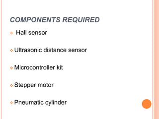
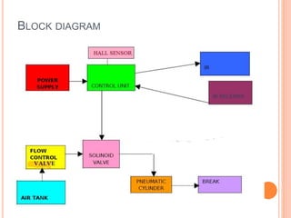
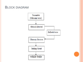
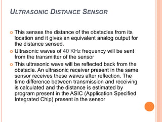
TEAM MEMBERS :
 K JITHENDRA - 15695A0309 ME
 C RAMA KRISHNA - 15695A0318 ME
 R JASWANTH RAJU - 15695A0415 ECE
 K LOKESH - 15695A0421 ECE
 U MAHENDRA NAIDU - 15695A0422 ECE
GUIDES NAME :
 Ms.CK.HEMANTHA LAKSHMI [ECE]
 Mr. GUNA SEKHAR [ME]
Introduction
Accidents occur due to technical problems
within the vehicle or due to the mistakes of the
drivers. Sometimes the drivers may become
fatigue and they lose the control over the vehicle
and sometimes the accidents occur due to
drunken drivers and sometimes due to rash
driving. In all these cases the accidents occur
because the brakes are not applied at right time.
REASONS FOR ACCIDENT
 Ignoring traffic rules
 Drunk driving
 Dreaming while driving
 Mechanical failures in the vehicle
 Mistakes of the drivers
VISION
Braking distance of a vehicle for a particular speed
is the distance at which the vehicle comes to a halt
from the current speed from the point of application
of the brakes. Here the speed of the vehicle is
sensed and the corresponding braking distance is
calculated using a microcontroller. The distance of
the obstacle in front is also sensed. The
microcontroller compares the two distances. If the
distances are within critical limits, the
microcontroller activates the brakes and slows
down the vehicle or brings the vehicle to a halt
before the obstacle thus avoiding the collision.
COMPONENTS REQUIRED
 Hall sensor
 Ultrasonic distance sensor
 Microcontroller kit
 Stepper motor
 Pneumatic cylinder
BLOCK DIAGRAM
HALL SENSOR
A Hall sensor is a transducer that varies its output
voltage in response to changes in magnetic field
density.
WORKING OF THE SENSOR
Two Magnets were fastened on the spokes of the
vehicle. Sensor is attached to the inner side of the
mud guard. When the wheel completes one
rotation a pulse will be coming out form the sensor.
This pulse is given as input to the microcontroller.
Features and Benefits
 Wide operating voltage range from 3.5V to 24V
 High magnetic sensitivity – Multi-purpose
 CMOS technology
 Low current consumption
Applications
 Automotive, Consumer and Industrial
Solid-state switch
 Brushless DC motor commutation
 Speed detection
 Linear position detection
 Angular position detection
 Proximity detection
ULTRASONIC SENSOR
The distance of any obstacle, a parked or a moving
vehicle, a road block, a tree in the roadside, is
sensed using an Ultrasonic sensor and it is fed to
the microcontroller.
.
 HC-SR04 Ultrasonic Distance Sensor is a popular and low
cost solution for non-contact distance measurement function.
It is able to measure distances from 2cm to 400cm with an
accuracy of about 3mm. This module includes ultrasonic
transmitter, ultrasonic receiver and its control circuit.
HC - SR04 module has 4 pins :
VCC – 5V, +ive of the power supply
TRIG – Trigger Pin
ECHO – Echo Pin
GND – -ive of the power supply
BLOCK DIAGRAM
ULTRASONIC DISTANCE SENSOR
 This senses the distance of the obstacles from its
location and it gives an equivalent analog output for
the distance sensed.
 Ultrasonic waves of 40 KHz frequency will be sent
from the transmitter of the sensor
 This ultrasonic wave will be reflected back from the
obstacle. An ultrasonic receiver present in the same
sensor receives these waves after reflection. The
time difference between transmission and receiving
is calculated and the distance is estimated by
program present in the ASIC (Application Specified
Integrated Chip) present in the sensor
SPECIFICATIONS
 Range : 1-32 ft.
 Resolution : .12 inches
 Signal Output : 0-5 Vdc
 Excitation Voltage : 12-24 Vdc
MICROCONTROLLER ATMEGA 18
The is a low power, high performance CMOS 8
bit microcomputer with 4k bytes of flash
programmable and erasable read only memory
(PEROM). It s a powerful microcomputer
providing highly flexible and cost effective
solution too many embedded control
applications.
Features
 High Performance, Low Power Atmel®AVR® 8-Bit Microcontroller
Family
 Advanced RISC Architecture
 131 Powerful Instructions
 Most Single Clock Cycle Execution
 32 x 8 General Purpose Working Registers
 Up to 20 MIPS Throughput at 20MHz
 High Endurance Non-volatile Memory Segments
 Data Retention: 20 years at 85°C/100 years at 25°C
Memory
– 1KBytes EEPROM
– 2KBytes Internal SRAM
– Write/Erase Cycles: 10,000 Flash/100,000 EEPROM
- 32KBytes of In-System Self-Programmable Flash
program
Other features
In-System Programming by On-chip Boot Program
– Programming Lock for Software Security
– Capacitive Touch Buttons, Sliders and Wheels
– Up to 64 sense channels
SPECIFICATIONS
 • Operating Voltage: 1.8 - 5.5V
 • Temperature Range: 40°C to 105°C
 • Speed Grade:
– 0 - 4MHz @ 1.8 - 5.5V
– 0 - 10MHz @ 2.7 - 5.5V
– 0 - 20MHz @ 4.5 - 5.5V
 Power Consumption at 1MHz, 1.8V, 25°C
 Active Mode: 0.2mA
 Power-down Mode: 0.1μA
 Power-save Mode: 0.75μA (Including 32kHz RTC)
STEPPER MOTOR
 A Stepper motor or step motor is a brushless
DC electric motor that divides a full rotation into a
number of equal steps.
 The motor’s position can be commanded to move
and hold at one of these steps without any
feedback sensor(open loop controller).as long as
the motor is carefully sized to the application in
respect to torque and speed.
SPECIFICATIONS
 Speed (without load): 7820 rpm
 594 g-cm Stall torque: 5596 g-cm
 Current draw (at 7820 rpm): 1.5A
 Nominal voltage: 12 VDC
 Operating voltage: 6 to 14 V DC Weight: 220 gm
(7.6 oz)
 Shaft diameter: 3.0 mm (1/8")
 Shaft length: 10.5 mm (1/2") ·
 Dimensions: 37.5 mm x 75 mm
PNEUMATIC CYLINDER
 Pneumatic cylinder(s) (sometimes known as air
cylinders) are mechanical devices which use the power of
compressed gas to produce a force in a reciprocating linear
motion.
 Like hydraulic cylinders, something forces a piston to move
in the desired direction. The piston is a disc or cylinder, and
the piston rod transfers the force it develops to the object to
be moved. Engineers sometimes prefer to use pneumatics
because they are quieter, cleaner, and do not require large
amounts of space for fluid storage.
ADVANTAGES :
 Accidents can be avoided
 Brake cost will be less.
 Free from wear adjustment.
 Less power consumption
 Less skill drivers is sufficient to operate.
 It gives very simplified operation.
 Installation is simplified
CONCLUSION
 The Intelligent Braking system, if implemented
can prevent accidents and can save valuable lives
and vehicle damaging.
 Implementation of such an advanced system can
be made compulsory similar to wearing of seat
belts so that accidents can be prevented to some
extent.
 Many companies such as BMW ,HONDA,BAJAJ
etc.,were implemented Such kind of projects in their
vehicles .Our intention is to reduce the cost of that
and give the product with less cost.
ANY QUERIES????

Intelligent braking system

  • 2.
    TEAM MEMBERS : K JITHENDRA - 15695A0309 ME  C RAMA KRISHNA - 15695A0318 ME  R JASWANTH RAJU - 15695A0415 ECE  K LOKESH - 15695A0421 ECE  U MAHENDRA NAIDU - 15695A0422 ECE GUIDES NAME :  Ms.CK.HEMANTHA LAKSHMI [ECE]  Mr. GUNA SEKHAR [ME]
  • 3.
    Introduction Accidents occur dueto technical problems within the vehicle or due to the mistakes of the drivers. Sometimes the drivers may become fatigue and they lose the control over the vehicle and sometimes the accidents occur due to drunken drivers and sometimes due to rash driving. In all these cases the accidents occur because the brakes are not applied at right time.
  • 4.
    REASONS FOR ACCIDENT Ignoring traffic rules  Drunk driving  Dreaming while driving  Mechanical failures in the vehicle  Mistakes of the drivers
  • 5.
    VISION Braking distance ofa vehicle for a particular speed is the distance at which the vehicle comes to a halt from the current speed from the point of application of the brakes. Here the speed of the vehicle is sensed and the corresponding braking distance is calculated using a microcontroller. The distance of the obstacle in front is also sensed. The microcontroller compares the two distances. If the distances are within critical limits, the microcontroller activates the brakes and slows down the vehicle or brings the vehicle to a halt before the obstacle thus avoiding the collision.
  • 6.
    COMPONENTS REQUIRED  Hallsensor  Ultrasonic distance sensor  Microcontroller kit  Stepper motor  Pneumatic cylinder
  • 7.
  • 8.
    HALL SENSOR A Hallsensor is a transducer that varies its output voltage in response to changes in magnetic field density.
  • 9.
    WORKING OF THESENSOR Two Magnets were fastened on the spokes of the vehicle. Sensor is attached to the inner side of the mud guard. When the wheel completes one rotation a pulse will be coming out form the sensor. This pulse is given as input to the microcontroller.
  • 10.
    Features and Benefits Wide operating voltage range from 3.5V to 24V  High magnetic sensitivity – Multi-purpose  CMOS technology  Low current consumption
  • 11.
    Applications  Automotive, Consumerand Industrial Solid-state switch  Brushless DC motor commutation  Speed detection  Linear position detection  Angular position detection  Proximity detection
  • 12.
    ULTRASONIC SENSOR The distanceof any obstacle, a parked or a moving vehicle, a road block, a tree in the roadside, is sensed using an Ultrasonic sensor and it is fed to the microcontroller.
  • 13.
    .  HC-SR04 UltrasonicDistance Sensor is a popular and low cost solution for non-contact distance measurement function. It is able to measure distances from 2cm to 400cm with an accuracy of about 3mm. This module includes ultrasonic transmitter, ultrasonic receiver and its control circuit. HC - SR04 module has 4 pins : VCC – 5V, +ive of the power supply TRIG – Trigger Pin ECHO – Echo Pin GND – -ive of the power supply
  • 15.
  • 16.
    ULTRASONIC DISTANCE SENSOR This senses the distance of the obstacles from its location and it gives an equivalent analog output for the distance sensed.  Ultrasonic waves of 40 KHz frequency will be sent from the transmitter of the sensor  This ultrasonic wave will be reflected back from the obstacle. An ultrasonic receiver present in the same sensor receives these waves after reflection. The time difference between transmission and receiving is calculated and the distance is estimated by program present in the ASIC (Application Specified Integrated Chip) present in the sensor
  • 17.
    SPECIFICATIONS  Range :1-32 ft.  Resolution : .12 inches  Signal Output : 0-5 Vdc  Excitation Voltage : 12-24 Vdc
  • 18.
    MICROCONTROLLER ATMEGA 18 Theis a low power, high performance CMOS 8 bit microcomputer with 4k bytes of flash programmable and erasable read only memory (PEROM). It s a powerful microcomputer providing highly flexible and cost effective solution too many embedded control applications.
  • 19.
    Features  High Performance,Low Power Atmel®AVR® 8-Bit Microcontroller Family  Advanced RISC Architecture  131 Powerful Instructions  Most Single Clock Cycle Execution  32 x 8 General Purpose Working Registers  Up to 20 MIPS Throughput at 20MHz  High Endurance Non-volatile Memory Segments  Data Retention: 20 years at 85°C/100 years at 25°C
  • 20.
    Memory – 1KBytes EEPROM –2KBytes Internal SRAM – Write/Erase Cycles: 10,000 Flash/100,000 EEPROM - 32KBytes of In-System Self-Programmable Flash program Other features In-System Programming by On-chip Boot Program – Programming Lock for Software Security – Capacitive Touch Buttons, Sliders and Wheels – Up to 64 sense channels
  • 21.
    SPECIFICATIONS  • OperatingVoltage: 1.8 - 5.5V  • Temperature Range: 40°C to 105°C  • Speed Grade: – 0 - 4MHz @ 1.8 - 5.5V – 0 - 10MHz @ 2.7 - 5.5V – 0 - 20MHz @ 4.5 - 5.5V  Power Consumption at 1MHz, 1.8V, 25°C  Active Mode: 0.2mA  Power-down Mode: 0.1μA  Power-save Mode: 0.75μA (Including 32kHz RTC)
  • 22.
    STEPPER MOTOR  AStepper motor or step motor is a brushless DC electric motor that divides a full rotation into a number of equal steps.  The motor’s position can be commanded to move and hold at one of these steps without any feedback sensor(open loop controller).as long as the motor is carefully sized to the application in respect to torque and speed.
  • 23.
    SPECIFICATIONS  Speed (withoutload): 7820 rpm  594 g-cm Stall torque: 5596 g-cm  Current draw (at 7820 rpm): 1.5A  Nominal voltage: 12 VDC  Operating voltage: 6 to 14 V DC Weight: 220 gm (7.6 oz)  Shaft diameter: 3.0 mm (1/8")  Shaft length: 10.5 mm (1/2") ·  Dimensions: 37.5 mm x 75 mm
  • 24.
    PNEUMATIC CYLINDER  Pneumaticcylinder(s) (sometimes known as air cylinders) are mechanical devices which use the power of compressed gas to produce a force in a reciprocating linear motion.  Like hydraulic cylinders, something forces a piston to move in the desired direction. The piston is a disc or cylinder, and the piston rod transfers the force it develops to the object to be moved. Engineers sometimes prefer to use pneumatics because they are quieter, cleaner, and do not require large amounts of space for fluid storage.
  • 25.
    ADVANTAGES :  Accidentscan be avoided  Brake cost will be less.  Free from wear adjustment.  Less power consumption  Less skill drivers is sufficient to operate.  It gives very simplified operation.  Installation is simplified
  • 26.
    CONCLUSION  The IntelligentBraking system, if implemented can prevent accidents and can save valuable lives and vehicle damaging.  Implementation of such an advanced system can be made compulsory similar to wearing of seat belts so that accidents can be prevented to some extent.  Many companies such as BMW ,HONDA,BAJAJ etc.,were implemented Such kind of projects in their vehicles .Our intention is to reduce the cost of that and give the product with less cost.
  • 28.